DILA Tech Guide.qxd - BigScreen.se
DILA Tech Guide.qxd - BigScreen.se
DILA Tech Guide.qxd - BigScreen.se

Create successful ePaper yourself
Turn your PDF publications into a flip-book with our unique Google optimized e-Paper software.
PROFESSIONAL<br />
D-ILA “ PROJECTOR
CONTENTS<br />
Preface 3<br />
Projector Development History and Background 3<br />
From ILA TM Projectors to D-ILA TM Projectors 4<br />
Structure and Basic Operating Principles of D-ILA TM 5<br />
Features of D-ILA TM 6<br />
Single D-ILA TM Color Projector 7<br />
Comparison with Competitive Systems 8<br />
D-ILA TM Picture Reproduction 9<br />
Summary : The Future of D-ILA TM 10<br />
Reference Materials (Illumination & Optics) 11
Preface<br />
Large-screen video is fast becoming an indispensable<br />
display device for applications that require greater<br />
pre<strong>se</strong>nce, appeal, and information distribution capabilities<br />
than is possible with conventional monitors.<br />
This shift to larger screens is mainly being facilitated<br />
by projectors, becau<strong>se</strong> they offer greater flexibility in<br />
terms of display size and greater compactness relative<br />
to the size of the display. At the same time, however,<br />
it is necessary that the projection device — the<br />
key component of the projector — is capable of withstanding<br />
a considerable degree of heat and light since<br />
very high levels of light are concentrated on a relatively<br />
small surface. The need for complex, advanced technology<br />
to attain high resolution further complicates<br />
the issue. Even now, engineers around the world are<br />
working to develop the next generation of high-performance<br />
projectors.<br />
In this document we will examine the basic operating<br />
principles, features, and future prospects of D-ILA TM .<br />
An understanding of the<strong>se</strong> basics will both aid in the<br />
introduction of new projectors and enable current<br />
projectors to be u<strong>se</strong>d more effectively.<br />
Projector Development History and<br />
Background<br />
In the 1940s, as black-and-white TVs were fast becoming a fixture<br />
in hou<strong>se</strong>holds in America and el<strong>se</strong>where, the development of largescreen<br />
displays was already underway. Initially, coincident with the<br />
development of TV receivers, the primary projection method was<br />
CRT ba<strong>se</strong>d. However, limits on light output soon led to the development<br />
of the light valve system, which made it possible to control<br />
more powerful light sources. In the 1950s, a black-and-white<br />
Eidophor system was commercialized using oil film target tubes.<br />
In the 1960s, both projectors and TVs were converted to color systems.<br />
In the ca<strong>se</strong> of projectors, a configuration of three oil film target<br />
tubes was u<strong>se</strong>d. In the 1970s, the Talaria system was introduced.<br />
Here, color signals were multiplexed and the number of oil<br />
film target tubes was reduced. This system enabled light output of<br />
a few thousand lumens, compared to the few hundred lumens<br />
possible with CRTs. The Eidophor and Talaria devices that u<strong>se</strong>d oil<br />
film target tubes required large vacuum devices. This increa<strong>se</strong>d<br />
the size and cost, as well as requiring more maintenance, due to<br />
the chemical changes in the oil film.<br />
By this time, however, re<strong>se</strong>arch had already begun on the possibility<br />
of using liquid crystal for u<strong>se</strong> in future flat panel displays and various<br />
display boards. By the 1980s, some manufacturers had begun<br />
applying transmissive and reflective liquid crystals to projectors. By<br />
the beginning of the 1990s, LCD projectors had been commercialized<br />
for the general market and and ILA TM projectors followed soon<br />
afterwards.<br />
In the mid-1990s, DLP TM projectors were introduced. The<strong>se</strong> u<strong>se</strong>d a<br />
DMD TM device, which modulated light with the mechanical vibration<br />
of ultra-small mirrors. With LCD projectors and ILA TM projectors<br />
already on the market, projection systems entered a new and<br />
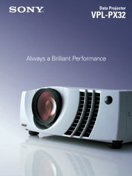
much more competitive era. Table 1 lists the types of projection<br />
methods and Figure 1 shows concept diagrams for each type of<br />
projection system.<br />
Table 1: Types of Projection Systems<br />
Projection system<br />
Self-light-emitting type<br />
Non-light-emitting type (light bulb)<br />
Transmissive type<br />
Reflective type<br />
CRT projector tube<br />
TFT LCD<br />
Oil film target<br />
ILA<br />
(Image Light Amplifier)<br />
3
Figure 1: Concept Diagrams and Features for Each Projection System<br />
Configuration Concept Diagram<br />
Features<br />
CRT<br />
CRT<br />
Signal input<br />
Projection lens<br />
Mature technology and low cost<br />
No p<strong>se</strong>udo-signals with no pixels<br />
Can handle specially shaped screens<br />
Resolution and light output inver<strong>se</strong>ly related<br />
Low output<br />
Large size and weight<br />
Oil film target<br />
type<br />
Lamp<br />
Vacuum chamber<br />
Spherical mirror<br />
Electron beam<br />
Oil film<br />
Light collecting lens<br />
Projection lens<br />
Mirror bar<br />
Signal input<br />
Writing and reading are <strong>se</strong>parated, so light output is higher<br />
No p<strong>se</strong>udo-signals with no pixels<br />
Can handle specially shaped screens<br />
High device costs<br />
Long startup time for vacuum device<br />
High maintenance costs<br />
Large size and weight<br />
Deterioration in S/N ratio due to film surface characteristics<br />
LCD ILA DLP<br />
Lamp<br />
Signal input LCD Projection lens<br />
Light collecting lens<br />
Polarizing plate<br />
PBS<br />
Signal input<br />
CRT<br />
Light collecting lens ILA<br />
Projection lens<br />
Lamp<br />
Light collecting lens<br />
Light collecting lens<br />
Lamp<br />
DMD<br />
Signal input<br />
Projection lens<br />
Can easily be made small and light<br />
Can be produced at low cost<br />
Easy optical configuration<br />
Resolution and light output inver<strong>se</strong>ly related<br />
Large device required for high light output<br />
Contrast limited (horizontal orientation)<br />
Provides both resolution and light output<br />
No pixels and no p<strong>se</strong>udo-signals<br />
Aperture ratio 100%<br />
High contrast<br />
Writing and reading are <strong>se</strong>parated, so high light output easily<br />
produced<br />
Can handle specially shaped screens<br />
Large size and weight<br />
Difficult to produce at low cost<br />
U<strong>se</strong>s natural light, giving it a high light efficiency ratio<br />
(in principle)<br />
High-speed respon<strong>se</strong> makes screen <strong>se</strong>quence color easy<br />
Tones managed easily with digital switching operations<br />
The device process includes mechanically moving<br />
parts and is complicated. Yields and costs are issues.<br />
The pixel pitch is restricted, so high resolutions require larger<br />
devices.<br />
The drive logic is complex.<br />
Meanwhile, following the development of conventional TVs, due to<br />
the maturity of the technology and their relatively low cost, CRT projectors<br />
had for many years dominated the projector market.<br />
However, in spite of technological advances, the<strong>se</strong> projectors<br />
remained plagued by insufficient light output and bulky, heavy<br />
designs. Eventually the CRT projection system was relegated to u<strong>se</strong><br />
in home projection TVs and specialist applications, while designs of<br />
other projectors were modified to incorporate to the newer systems.<br />
Similarly, the Eidophor and Talaria devices were pha<strong>se</strong>d out<br />
becau<strong>se</strong> the vacuum devices they required means that they were<br />
too large, heavy and expensive to compete with the newer systems.<br />
From ILA TM Projectors to D-ILA TM Projectors<br />
Around the start of the 1970s, re<strong>se</strong>arch was carried out at Hughes<br />
Aircraft into optic writing spatial modulation devices and in the<br />
1980s, projectors using this device came into practical u<strong>se</strong> (even<br />
though they were restricted to still-picture images). Continuous<br />
improvements eventually made it possible for the<strong>se</strong> devices to han-<br />
4<br />
dle moving images and by the end of the 1990s, the technology<br />
for moving images was firmly established.<br />
At the same time, JVC (Victor Company of Japan, Limited), was<br />
carrying out re<strong>se</strong>arch and development on projection methods suitable<br />
for the anticipated large-screen pictures. Determining that the<br />
optic writing spatial modulation devices were optimum for this purpo<strong>se</strong>,<br />
JVC’s R&D focu<strong>se</strong>d on practical implementation of this technology.<br />
Hughes Aircraft and JVC joined forces to develop a marketable<br />
projector and in 1993 introduced the ILA TM (Image Light<br />
Amplifier) projector. This was immediately recognized in the market<br />
as the new standard for large screen projectors in the <strong>se</strong>cond half<br />
of the 1990s.<br />
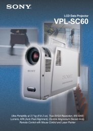
As Figure 2 shows, the ILA TM projector device is compri<strong>se</strong>d of a<br />
number of layers of 0 thin-film that are sandwiched between two<br />
glass substrates. The thin-film structure has four layers: an optoelectrical<br />
conductive layer, a light cut-off film, dielectric mirrors, and<br />
liquid crystal with ultra-fine processing to generate pixels. As<br />
Figure 1 shows, the device operates with two-dimensional CRT<br />
optical images as the writing light, forms the images in the optoelectrical<br />
conductive layer, and varies the impedance of the optic-
electrical conductive layer according to the strength of the optical<br />
image. As a result, the AC voltage applied to the liquid crystal layer<br />
changes to match the optical image and optical modulation is<br />
applied to the reading light. The modulated light is branched at the<br />
PBS (Polarized Beam Splitler) surface to the light source side and<br />
the projection side linked with the strength of the writing light.<br />
The features of the ILA TM projectors are as follows.<br />
➀The reading light that determines the optical output is reflected by<br />
dielectric mirrors, with an aperture ratio of 100%, so high brightness<br />
projection is possible.<br />
➁The writing light that determines the resolution is ultra-low, so<br />
the CRT beam size is ultra fine. Con<strong>se</strong>guently very high resolution<br />
can be easily attained.<br />
➂The liquid crystal vertical layout, once considered difficult for<br />
mass production, is mass produced for the first time,<br />
providing very high contrast.<br />
➃There is no pixel structure, so distortion-free reproduction, free<br />
of any p<strong>se</strong>udo-images is possible for all types of input signals.<br />
In other words, by <strong>se</strong>parating the light output (who<strong>se</strong> pha<strong>se</strong> is easily<br />
shifted), and the resolution, the writing light and the reading light (with<br />
dielectric mirrors), this is the first technique to provide both very high<br />
light output and high resolution. Furthermore, this system has the<br />
added advantage of distortion free image combined with very high<br />
contrast. This allows superior quality images from the ILA TM projector.<br />
Figure 2: Basic Composition of ILA TM Device<br />
dia applications.<br />
JVC has developed its own new projection method that resolves<br />
Issues ➀ and ➁ while retaining the high light output, high resolution,<br />
and high contrast provided by ILA TM projectors. To meet<br />
market demand for a mainstream projection technique for the 21st<br />
century, JVC introduced its "D-ILA TM Multimedia Projector" at the<br />
beginning of 1998.<br />
Structure and Basic Operating Principles of<br />
D-ILA TM<br />
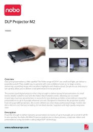
As Figure 3 shows, the basic structure of D-ILA TM devices is<br />
LCOS (Liquid Crystal on Silicon). Aluminum reflective electrodes,<br />
corresponding to each pixel, are laid out on the CMOS board making<br />
up the X-Y matrix that <strong>se</strong>lects the pixel address. After this surface<br />
is flat proces<strong>se</strong>d, the vertical film is formed. On the other<br />
glass board, the transparent electrode layer and the vertical film are<br />
placed. The liquid crystal layer is <strong>se</strong>aled between the facing films.<br />
Figure 3: Basic Structure of D-ILA TM Devices<br />
Glass Substrate<br />
Alignment Layer<br />
Transparent Electrode<br />
Liquid Crystal<br />
Reflective Electrode<br />
Wiring Shield Layer<br />
ITO Electrode Dielectric Mirror Glass Substrate<br />
Photo Sensor<br />
Projection Light<br />
Writing Light<br />
Si Substrate<br />
Source Gate Drain Capacitor<br />
Sectional view<br />
Wiring Layer<br />
Front view<br />
Optical Glass Substrate<br />
Alignment Layer<br />
Liquid Crystal<br />
ITO Electrode<br />
Light Blocking Layer<br />
While ILA TM projectors are high-resolution projectors that realize light<br />
output of up to 12,000 lumens, boundary resolution of 1,600 TV<br />
lines, and contrast of over 1,000 to 1, some problematic issues<br />
remain.<br />
➀Becau<strong>se</strong> the ILA TM is u<strong>se</strong>d as the projecting device and a CRT for<br />
the writing light, two key devices are required. As a result,<br />
costs can qucikly escalate as does size and weight.<br />
➁The writing optic image is formed with an electron beam that has<br />
a diameter, so even though the boundary resolution is high,<br />
as the optical image spatial frequency ri<strong>se</strong>s, the MTF (modulation<br />
transmission function) gradually decrea<strong>se</strong>s. This can lead to<br />
diminished legibility of very small letters.<br />
In recent years, thanks to increa<strong>se</strong>s in computer capacity and<br />
speed, together with decreasing costs, pre<strong>se</strong>ntations which include<br />
graphics and text have become commonplace. It is expected that<br />
➁ above may reduce the suitability of ILA TM projectors for multime-<br />
The D-ILA TM device’s reflective technique involves laying out the<br />
pixel address <strong>se</strong>lection <strong>se</strong>ction and the light modulation <strong>se</strong>ction<br />
liquid crystal in three dimensions. The entire surface, except for the<br />
insulation <strong>se</strong>ction between pixel electrodes, is u<strong>se</strong>d as a reflective<br />
surface, so a very high aperture ratio is possible. Also, thanks to<br />
the high aperture ratio, high intensity light can be handled, making<br />
it easy to convert to higher light output.<br />
The vertical orientation that has proven it<strong>se</strong>lf on ILA TM projectors, is<br />
u<strong>se</strong>d for the liquid crystal layer, so high contrast is obtained.<br />
Depending on the optical system <strong>se</strong>lected, a contrast of over<br />
1,000 to 1 is possible.<br />
The resolution is determined by the size of the cells on the CMOS<br />
board. Given the sub-micron scaling of current CMOS memory<br />
ICs, even the pixels for full HDTV (1,920 x 1,080 pixels) can be fitted<br />
onto a CMOS board of less than 1 inch across, providing ultrahigh<br />
resolution.<br />
5
Figure 4: Basic Structure of D-ILA TM Projector<br />
Video<br />
signal<br />
D-ILA device<br />
PBS<br />
Light<br />
collecting lens<br />
Projection lens<br />
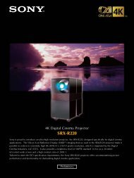
Figure 4 shows how a D-ILA TM projector operates. The natural light<br />
from the light source is <strong>se</strong>parated by the PBS (polarized beam splitter)<br />
into a P wave component (light vibrating parallel to the surface)<br />
and an S wave component (light vibrating perpendicular to the surface.)<br />
The P wave component proceeds straight through the PBS.<br />
Since it is unnecessary light, it is not u<strong>se</strong>d. Only the S wave component<br />
reaches the D-ILA TM elements. The light that has reached<br />
the elements pas<strong>se</strong>s through the liquid crystal layer, is reflected by<br />
the pixel electrodes, pas<strong>se</strong>s through the liquid crystal layer again,<br />
and reaches the PBS. At this time, the component that was modulated<br />
in the liquid crystal layer is converted into P waves and after it<br />
has pas<strong>se</strong>d through the PBS, is projected onto the screen through<br />
the projection lens. On the other hand, the S wave component that<br />
was not modulated is reflected by the PBS and returns to the light<br />
source, so it does not contribute to the projection image.<br />
Figure 5 shows the optic modulation characteristics for the vertically<br />
oriented liquid crystal. (a) is for when there is no modulation and<br />
(b) is for when there is modulation. When the input signal to the<br />
device is black, voltage is not applied to the pixel electrode, the<br />
liquid crystal layer remains in its vertical orientation (as shown in the<br />
diagram), the light axis of S wave and liquid crystal long axis are<br />
parallel, and optic modulation does not take place in the liquid crystal<br />
layer. The light input, as S waves, is output as it is (without<br />
modulation) and reflected by the PBS. As a result, this light does<br />
not reach the screen and it reproduces the black state. The high<br />
contrast characteristic of the vertically oriented liquid crystal is for<br />
black reproduction, when the liquid crystal is not modulated. This<br />
is how true black is obtained. (b) shows the state in which voltage<br />
is applied to the pixel electrode. Since the liquid crystal is the n<br />
type, the long axis tilts in the direction perpendicular to the applied<br />
electric field. At this time, the axis of the incoming S wave light and<br />
the long axis of the liquid crystal inter<strong>se</strong>ct. Due to the compound<br />
refraction of the liquid crystal, the light is converted into elliptically<br />
polarized light and circularly polarized light, a P wave component is<br />
generated, and the projected optical image is formed on the<br />
screen. The maximum modulation of the liquid crystal occurs when<br />
all the S waves coming into the device are converted into P waves<br />
to reproduce a white image.<br />
Figure 5: Modulation Characteristic of Vertically<br />
Oriented Liquid Crystal<br />
When not modulated<br />
(a)<br />
When modulated<br />
(b)<br />
Features of D-ILA TM<br />
The features of D-ILA TM are as shown in Table 2. Becau<strong>se</strong> of the<br />
high aperture ratio, any ri<strong>se</strong> in the temperature of the device due to<br />
photothermal conversion and any malfunctioning of drive elements<br />
due to photoelectric conversion is minimal. Therefore, it is possible<br />
to handle high intensity light. Moreover, the resolution is determined<br />
by the CMOS process scaling, as discus<strong>se</strong>d above. So pixel pitches<br />
of only a few microns are possible and, as mentioned previously, the<br />
pixels for full HDTV (1,920 x 1,080 pixels) can fit onto a CMOS board<br />
less than 1 inch across. Also, the vertical orientation of the liquid<br />
crystal is fully utilized. The high light output, high resolution, and high<br />
contrast of the conventional ILA TM are retained, while shape, weight,<br />
and cost issues of the ILA TM are resolved by converting the writing<br />
method from an optical image to direct writing with electrical signals.<br />
Table 2: D-ILA TM Projector Features<br />
High resolution<br />
High aperture ratio<br />
High light output<br />
High contrast<br />
High-speed<br />
respon<strong>se</strong><br />
Compact, lightweight<br />
Currently, this is the element with the highest<br />
possible density. When pixel size is the<br />
same, it provides the highest resolution;<br />
when resolution is the same, it has the smallest<br />
pixel size.<br />
As long as the insulation between pixel electrodes<br />
is maintained, the size of the nonopening<br />
<strong>se</strong>ction can be minimized, so resolution<br />
can be rai<strong>se</strong>d with only a minimal<br />
reduction in the aperture ratio.<br />
The aperture ratio and light output are proportional<br />
and the non-opening <strong>se</strong>ction is<br />
small. As a result, photothermal conversion is<br />
minimal, the light withstand level for the elements<br />
is high, and powerful light sources can<br />
be u<strong>se</strong>d.<br />
The vertically oriented crystal provides a nomodulation<br />
state, so the highest contrast of<br />
a few thousand to one can be attained for<br />
the element alone.<br />
With the reflective type, light is modulated<br />
while it goes back and forth. As a result, the<br />
thickness of the liquid crystal layer is half that<br />
of the transmissive type, the electric field<br />
boundary strength gw is double, and highspeed<br />
respon<strong>se</strong> is possible.<br />
The high pixel density and high aperture ratio<br />
allows the elements to be light and compact.<br />
Development of color projectors<br />
Figure 6 shows the configuration of a three-D-ILA TM projector. The<br />
first and <strong>se</strong>cond “fly-eye” lens plates and the PS composite plates<br />
sandwiched between them convert the natural white light of the light<br />
source into S wave. This rai<strong>se</strong>s the operating efficiency of the light<br />
source and improves the uniformity of the amount of light on the<br />
screen at the same time. Sub<strong>se</strong>quently, the light is <strong>se</strong>parated into<br />
RGB (red, green, blue) components through color photospectrometry<br />
and each color is input to the corresponding PBS. The S wave<br />
component, reflected by the PBS, becomes the P wave component<br />
modulated by the liquid crystal as shown in Figure 4 and discus<strong>se</strong>d<br />
above. Only this component pas<strong>se</strong>s through the PBS, while the RGB<br />
is synthesized by the cross-dichroic prism, and projected onto the<br />
screen as a color image through the projection lens.<br />
The three-panel projector is the most fundamental method for handling<br />
color. This is a system in which the light utilization efficiency is<br />
high and projector performance, color reproduction, contrast, and<br />
6
esolution are determined directly by the device characteristics. On<br />
the other hand, tiny differences in registration and uniformity among<br />
the R, G, and B devices can directly influence the picture quality.<br />
Since three devices are required and color <strong>se</strong>paration and color synthesis<br />
optical systems are necessary, this can lead to high cost and<br />
large size. Therefore, although the three-panel system is suitable for<br />
professional u<strong>se</strong>, it is not suitable for consumer systems which<br />
require lower prices. In order to develop an affordable consumerlevel<br />
system, it is necessary to reduce the number of devices and<br />
further reduce the size and cost of the optical systems.<br />
Figure 6: Structure of Three-D-ILA TM Projector<br />
Projection lens<br />
B-PBS<br />
R-PBS<br />
Blue D-ILA<br />
Color <strong>se</strong>paration<br />
cross-dichroic<br />
G-PBS<br />
Green<br />
D-ILA<br />
Single D-ILA TM Color Projector<br />
Mirror<br />
Lamp<br />
R/G Light<br />
collecting lens<br />
Mirror<br />
Methods propo<strong>se</strong>d for reducing the number of devices include ( i )<br />
surface <strong>se</strong>quencing that multiplexes the colors on the time axis and<br />
(ii) simultaneous point <strong>se</strong>quencing that multiplexes the colors in<br />
space.<br />
Surface <strong>se</strong>quencing synchronizes with the field frequency and<br />
applies the RGB light <strong>se</strong>quentially. It has the advantage that the<br />
device resolution is output as is, but it requires that the field drive<br />
frequency is three times the incoming frequency. Also, due to time<br />
difference, color mixing, field flicker, etc., p<strong>se</strong>udo-signals can occur<br />
easily, depending on the color disruption and drive conditions.<br />
The point <strong>se</strong>quence method allocates each pixel within the screen<br />
and features simultaneous equations. Color disruption, color mixing,<br />
and flicker are less likely to occur and quality equivalent to that<br />
of a three-panel type projector, can be obtained. However, three<br />
times the number of pixels are required relative to the resolution,<br />
making ultra-high density devices indispensable.<br />
The problem with both methods is with the basic principle; that is, if<br />
the colors are simply multiplexed, the light utilization efficiency drops<br />
to 1/3. For single D-ILA TM projectors, the high-density characteristic<br />
of the device it<strong>se</strong>lf is utilized. By combining this with a hologram<br />
color filter, it has been possible to develop single D-ILAs TM that minimize<br />
the drop in light utilization efficiency. The<strong>se</strong> were first shown in<br />
late 1999 and introduced to the market during 2000 in the form of<br />
consumer projection TVs.<br />
Figure 7 shows basic principles of the structure and color multiplexing<br />
for the D-ILA TM hologram device u<strong>se</strong>d in the single-panel<br />
system. The pixel electrodes are formed on the CMOS IC board<br />
and the device compri<strong>se</strong>s an orientation film, liquid crystal layer, and<br />
transparent electrodes. This is the same as for D-ILA TM devices.<br />
However, by placing a hologram color filter (HCF) on top of the<br />
transparent structure, the RGB point <strong>se</strong>quence is established for<br />
each pixel.<br />
This hologram rai<strong>se</strong>s the diffraction efficiency for the incoming pure<br />
white light with the aim of improving the light utilization efficiency<br />
and making the light come in at an angle. As the figure shows,<br />
after the light is split into RGB components and pas<strong>se</strong>s through the<br />
liquid crystal layer, it is concentrated on each pixel electrode by the<br />
diffraction wavelength dependence. The RGB light is reflected by<br />
R<br />
G<br />
B<br />
the pixel electrodes, pas<strong>se</strong>s through the liquid crystal layer again,<br />
and arrives at the HCF. Since this light comes into the HCF at a<br />
right angle, it pas<strong>se</strong>s through the HCF with almost no diffraction<br />
effect. While the light is passing back and forth through the liquid<br />
crystal layer, it is optically modulated according to the input signal<br />
level — the same as with D-ILA TM devices — and projection light<br />
corresponding to that amount is created.<br />
When shifting to the color system, this device requires three times<br />
as many pixels as the required resolution. All this can be made<br />
possible thanks to the high density characteristics of D-ILA TM .<br />
Figure 7: Structure of D-ILA TM Hologram Device<br />
B G R<br />
Hologram<br />
color filter<br />
Reflective<br />
pixel electrode<br />
B<br />
G R B G R B G R<br />
White<br />
incoming light<br />
Liquid<br />
crystal layer<br />
Silicon<br />
substrate<br />
Figure 8 shows the configuration of the single D-ILA TM projector<br />
with the D-ILA TM hologram device. The light from the light source<br />
travels via the cold mirror, the visible light component is concentrated<br />
by the light collecting lens, aligned as a straight-line polarized<br />
light component at the incoming-side PBS, and input to the<br />
D-ILA TM hologram device at an angle. Only the light that has been<br />
optically modulated in the device pas<strong>se</strong>s through the output-side<br />
PBS and is projected onto the screen through the projection lens.<br />
Figure 8: Basic Structure of Single D-ILA TM<br />
Lamp<br />
Hologram<br />
D-ILA device<br />
Table 3: Device Dimensions<br />
Mirror<br />
Light collecting lens<br />
Projection lens<br />
Table 3 gives the specifications for the currently u<strong>se</strong>d D-ILA TM<br />
device and the D-ILA TM hologram device.<br />
The hologram device attains a horizontal pixel pitch of 22.8/3 =<br />
7.6µm, enabling the highest density level and <strong>se</strong>curing an aperture<br />
ratio of 88%. The contrast makes u<strong>se</strong> of the vertical orientation<br />
and reaches a few thousand to one for the device it<strong>se</strong>lf. Though it<br />
depends on a combined optical system, it is possible to <strong>se</strong>cure a<br />
contrast ratio of 1,000:1 in a projector.<br />
D-ILA device D-ILA hologram device<br />
Pixel size (diagonal) 0.907 inch (4:3) 1.22 inch (16:9)<br />
Number of pixels 1,365 x 1,024 dots 1,280 (x3) x 1,028 dots<br />
Pixel pitch 13.5x13.5 µm 22.8/3=7.6 µm<br />
Aperture ratio 93% 88%<br />
Contrast ratio<br />
(theoretical)<br />
>2,000:1 >1,000:1<br />
Respon<strong>se</strong> speed Rising + falling < 16 ms Rising + falling < 16 ms<br />
7
Comparison with Competitive Systems<br />
Figure 9 shows the composition of current mainstream projection<br />
devices and Table 4 compares the performance of the various<br />
methods with the triple color method. DLP TM switches the double<br />
stable angle of micro-mirrors digitally to modulate the light path and<br />
reproduces tones according to changes in light. Since natural light<br />
is u<strong>se</strong>d as is, high light utilization efficiency can be expected.<br />
However, there is a strong relationship between mirror weight and<br />
the twisted hinge, restricting pixel size flexibility. It is estimated that<br />
the best pixel pitch that can currently be attained is from a few µm<br />
to 20+µm. Shifting to higher resolutions will require larger chip surface<br />
areas and is expected to cau<strong>se</strong> deterioration of pixel yields<br />
and make mass production difficult.<br />
LCDs u<strong>se</strong> transmissive light, so the optical configuration of the system<br />
is relatively simple. Even with a triple system, the device can<br />
easily be made compact and lightweight and low cost can be<br />
attained. On the other hand, since transmissive light <strong>se</strong>ction, the<br />
address lines, signal lines, and drive elements are all laid out on the<br />
same surface, an increa<strong>se</strong> in the number of pixels will decrea<strong>se</strong> the<br />
aperture ratio. Becau<strong>se</strong> in this system, resolution and light output<br />
generally have an inver<strong>se</strong> relationship, it is more appropriate for<br />
mobile and portable units than for ultra-high resolution and ultrahigh<br />
brightness.<br />
Figure 9: Structure of Each Projection Device<br />
D-ILA 0.9": 1,400,000 pixels DMD 1.1": 1,300,000 pixels LCD 1.3" or 1.8": 1,300,000 pixels<br />
Device<br />
• Liquid crystal polarized modulation<br />
• Analog gradation<br />
• U<strong>se</strong>s polarized light (PS composition<br />
is needed)<br />
• Ultra high density<br />
• Ultra high aperture ratio<br />
• Micro mirror angle modulation<br />
• Digital gradation<br />
• U<strong>se</strong>s natural light<br />
• Limited pixel pitch<br />
• High aperture ratio<br />
• Yield difficulty<br />
• Liquid crystal light modulation<br />
• Analog gradation<br />
• U<strong>se</strong>s polarized light (PS composition is<br />
needed)<br />
• Low density<br />
• Low aperture ratio<br />
Optical system<br />
• Reflective type<br />
• Quasi-shurilen <strong>se</strong>paration<br />
• Clo<strong>se</strong> relationship between cone<br />
angle and device angle<br />
(More freedom of F value, High<br />
light efficiency ratio)<br />
• 3P composition<br />
• Middle light path length<br />
• Reflective type<br />
• PBS <strong>se</strong>paration<br />
• Inver<strong>se</strong> relationship between cone<br />
angle and contrast<br />
(Telecen system, Limited F value,<br />
Pha<strong>se</strong> compensation)<br />
• 3P/4P composition<br />
• Long light path length<br />
• Transmissive type<br />
• Polarization plate <strong>se</strong>paration<br />
• Inver<strong>se</strong> relationship between light<br />
amount and temperature of polarization<br />
plate<br />
(Adoption of intake side PBS, Large<br />
device size)<br />
• 4P composition<br />
• Short light path length<br />
High Resolution<br />
Device size comparison for the same resolution<br />
The smaller the size, the higher the resolution<br />
D-ILA<br />
(operable limit)<br />
Single D-ILA made possible<br />
D-ILA can have both high<br />
resolution and high brightness<br />
High Brightness<br />
Available space for device’s light utilization<br />
The larger the size, the higher the brightness<br />
D-ILA<br />
(current model)<br />
DMD<br />
Single-panel color projection<br />
is possible<br />
S-D-ILA<br />
LCD<br />
LCD<br />
DMD<br />
D-ILA<br />
As mentioned above, becau<strong>se</strong> D-ILA TM has pixel densities and<br />
aperture ratios superior to other systems, it is possible to produce<br />
ultra-high light output and ultra-high resolution. Also, by using the<br />
high density characteristic, the size of the pixel chip can be<br />
reduced compared to other units at the same resolution. This<br />
means that this system is applicable to portable and mobile systems.<br />
The D-ILA TM system is considered ideal for the highresolution<br />
era of the 21st century.<br />
8
Table 4: Performance Comparison for Different Systems<br />
Resolution<br />
Aperture ratio<br />
High pixel density<br />
High light output<br />
Light efficiency<br />
ratio<br />
Contrast ratio<br />
Ea<strong>se</strong> of optical<br />
configuration<br />
Element cost (yield)<br />
D-ILA DLP LCD<br />
Excellent<br />
(1365 x 1024)<br />
Excellent<br />
(93%)<br />
Excellent<br />
(7 µm pitch)<br />
Excellent<br />
(10 klm or more<br />
possible)<br />
Good<br />
(Polarized light)<br />
Excellent<br />
(Vertical orientation)<br />
Good<br />
Good<br />
Good<br />
(1280 x 1024)<br />
Excellent<br />
(91%)<br />
Good<br />
(17 µm pitch)<br />
Excellent<br />
(10 klm or more<br />
realized)<br />
Excellent<br />
(Natural light)<br />
Good<br />
Good<br />
Fair<br />
Fair<br />
(1280 x 1024)<br />
Fair<br />
(65%)<br />
Fair<br />
(25 µm pitch)<br />
Good<br />
(larger pixels for<br />
higher output)<br />
Good<br />
(Polarized light)<br />
Fair<br />
Excellent<br />
(Transmissive type)<br />
Excellent<br />
The only methods to eliminate this are either ( i ) a complete inpha<strong>se</strong><br />
state or (ii) to u<strong>se</strong> the sampling theorem shown in the figure<br />
and sample with a spatial frequency of at least double the input<br />
signal (display with resolution 2x or greater).<br />
The in-pha<strong>se</strong> state means a display of 1:1 with the number of<br />
pixels for S-XGA input. Also, when displaying XGA input using the<br />
number of pixels for S-XGA, the edges are not displayed and the<br />
pixels are displayed 1:1. For this reason, many projectors have a<br />
function that allows the resizing mode to be switched off. On the<br />
other hand, when the resolution of the projector it<strong>se</strong>lf is lower than<br />
that of the input signals, it is impossible to display images without<br />
the generation of p<strong>se</strong>udo-signals.<br />
The pictures in Figure 11 show the stage of generation of p<strong>se</strong>udosignals<br />
depending on the resolution, using a circular zone chart —<br />
a typical pattern with various spatial frequencies. As can be <strong>se</strong>en<br />
from this reproduced image, it is not simply enough that the projector<br />
resolution be equal to or greater than the resolution of the input<br />
signals. Rather it must be sufficient to ensure that p<strong>se</strong>udo-signals<br />
are not generated when input signals are reproduced.<br />
Respon<strong>se</strong> speed<br />
Real time<br />
characteristic<br />
Development to<br />
single-panel<br />
projector<br />
Good<br />
Good<br />
Excellent<br />
Excellent<br />
Fair<br />
(Frame memory)<br />
Good<br />
(Surface <strong>se</strong>quence)<br />
Good<br />
Good<br />
Fair<br />
(Larger pixels)<br />
Figure 11: Specific Example of P<strong>se</strong>udo-Signals<br />
(Example of moire due to circular zones)<br />
D-ILA TM Picture Reproduction<br />
Circular zone chart<br />
VGA<br />
S-VGA<br />
➀ High-resolution<br />
Naturally, the larger the screen, the greater resolution is required.<br />
Current resolution requirements can generally be <strong>se</strong>parated into<br />
that for computer displays centering on text and graphics on the<br />
one hand and video displays on the other. Even for computer displays,<br />
S-XGA level resolution can be supported adequately. At the<br />
workstation level, most requirements for U-XGA resolution can be<br />
handled. On the other hand, for video displays, although full support<br />
for 720p/1080i is hoped for with the future standardization of<br />
HDTV, this has not yet been commercialized.<br />
To respond to the need for high-resolution displays and display various<br />
types of signals from different multimedia applications, many<br />
projectors u<strong>se</strong> a resizing technique with pixel density conversion.<br />
However, if the projector resolution is insufficient, the display image<br />
is compres<strong>se</strong>d and information is lost Also, even if the resolution is<br />
greater than that of the input signals, resampling can generate<br />
p<strong>se</strong>udo-signals called fold-back distortion.<br />
Figure 10 shows this state. The spatial frequency of the input signal<br />
and side-band components generated with the sampling frequency<br />
which corresponds to the projector’s pixels are mixed in.<br />
This results in the generation of a p<strong>se</strong>udo-signal (shown with diagonal<br />
lines) that produces fold-back distortion when converted into<br />
low-band components. This appears as moire and jaggedness<br />
and cau<strong>se</strong>s drastic deterioration of the picture quality.<br />
Relative energy<br />
Figure 10: P<strong>se</strong>udo-Signals due to Sampling<br />
Input signal band<br />
Fold-back distortion<br />
(p<strong>se</strong>udo-signal)<br />
Spatial frequency<br />
Side band<br />
Sampling frequency<br />
(number of pixels)<br />
State with Fold-Back Distortion Occurring<br />
Relative energy<br />
Input signal band<br />
Spatial frequency<br />
Side band<br />
Sampling frequency<br />
(number of pixels)<br />
State with Fold-Back Distortion Not Occurring<br />
XGA<br />
S-XGA<br />
Q-XGA<br />
Considering the variety of multimedia signal formats, it is obvious<br />
that higher and higher resolution will be needed to completely<br />
avoid the generation of p<strong>se</strong>udo-signals. The high-density configuration<br />
of D-ILA TM is ideal for this.<br />
➁ High aperture ratio<br />
We have already mentioned how a high aperture ratio is good for<br />
high light output becau<strong>se</strong> it improves light efficiency and minimizes<br />
light absorption. It also has a major impact on the quality of reproduced<br />
pictures. For example, when the input signal is all white, if it<br />
is projected with a low aperture ratio, lattice stripe noi<strong>se</strong> and extraneous<br />
p<strong>se</strong>udo-signals will be generated in the original picture.<br />
Therefore, the higher the aperture ratio, the fewer the artifacts so<br />
that the image reproduced will be smoother.<br />
The circular zone chart (discus<strong>se</strong>d above) in Figure 12 shows how<br />
the aperture ratio affects the amount of fold-back distortion (p<strong>se</strong>udo-signal)<br />
that appears in the reproduced image. On the left, we<br />
can <strong>se</strong>e the image condition when the aperture ratio is 90%, and<br />
on the right, we <strong>se</strong>e the results when the aperture ratio is 65%. It is<br />
obvious that the higher the aperture ratio, the less fold-back distortion<br />
occurs. 1/2 fold-back distortion is significantly reduced, and<br />
there is almost no 1/4 distortion whatsoever at the high aperture<br />
ratio.<br />
The impact of fold-back distortion on the reproduced image also<br />
depends on the frequency of the band that the distortion is folded<br />
back to; the lower the band, the lower the picture quality. Here<br />
again, a device with a high aperture ratio that produces minimal<br />
9
1/2 or 1/4 fold-back distortion is definitely advantageous.<br />
The D-ILA TM device allows a high aperture ratio to be maintained<br />
even when resolution is increa<strong>se</strong>d. With both high resolution and<br />
high aperture ratio, the D-ILA TM device is much better at reducing<br />
fold-back distortion than other types of devices.<br />
Figure 12: Fold-Back Distortion Status<br />
At Different Aperture Ratios<br />
High aperture ratio<br />
(90%)<br />
c<br />
b<br />
a<br />
c<br />
Low aperture ratio<br />
(65%)<br />
b<br />
c<br />
with vertical orientation, and smaller size with high pixel density —<br />
make it the ideal projection solution for large-screen display systems.<br />
Figure 13 shows the current state of D-ILA TM devices and prototypes<br />
such as an HDTV-ready single-panel hologram D-ILA TM , Q-<br />
XGA mode for full HDTV, as well as a device with 4000x1000-pixel<br />
capability. The<strong>se</strong> examples make it abundantly clear that the<br />
D-ILA TM system has enormous potential for development. It is safe to<br />
say that D-ILA TM is the only current system that can handle even<br />
higher performance.<br />
When commercialization of D-ILA TM began, the system offered S-<br />
XGA resolution capability. This is still more than sufficient to meet the<br />
majority of current market demands for high resolution and high picture<br />
quality, but it is only natural that picture performance requirements<br />
will continue to ri<strong>se</strong>. In order to meet this market demand,<br />
JVC is working to boost D-ILA TM performance to conform with future<br />
needs and form the basis of the next generation of large-screen<br />
image systems.<br />
a<br />
c<br />
a<br />
c<br />
a<br />
Figure 13: Various Types of D-ILA TM Devices<br />
c<br />
b<br />
b<br />
c<br />
a<br />
c<br />
a<br />
b<br />
c<br />
: 0 fold-back distortion<br />
:1/2 fold-back distortion<br />
:1/4 fold-back distortion<br />
0.7" S-XGA<br />
➂ Contrast<br />
Generally, text and other information can be viewed adequately at a<br />
contrast ratio of 50:1 or higher. Most audiences will accept a contrast<br />
ratio of 100:1 or higher for text and data. This is the ca<strong>se</strong> when<br />
the peak signal is displayed at 100% on the screen. However, if<br />
viewing a dark video source (a night-time scene, for example), the<br />
peak signal level falls below 1/3 and the contrast on the screen falls<br />
below 1/3, reducing contrast ratio. This is the main reason that<br />
many data projectors, which are u<strong>se</strong>d mainly for text display, <strong>se</strong>t their<br />
contrast ratios between 100:1–200:1. However, nowadays with<br />
video images begining to be incorporated frequently in computerba<strong>se</strong>d<br />
pre<strong>se</strong>ntations, even data projectors are starting to need the<br />
same level of contrast required in a video system. Under the<strong>se</strong> circumstances,<br />
it is necessary that the projector components them<strong>se</strong>lves<br />
offer high-contrast performance. Again, D-ILA TM , with its vertically<br />
oriented liquid crystals, which has a high contrast of a few thousand<br />
to one, provides an excellent solution for future development.<br />
0.9" S-XGA<br />
Summary: The Future of D-ILA TM<br />
1.3" Q-XGA<br />
The key advantage of the D-ILA TM system is that it enables the highest<br />
density pixel integration, making it suitable for high resolution picture<br />
reproduction. Also, even at higher resolutions, there is almost<br />
no drop in the aperture ratio, so very high light output is possible.<br />
Becau<strong>se</strong> the D-ILA TM system provides both high light output and<br />
high resolution, it meets all the performance requirements of projectors.<br />
Moreover, D-ILA TM ’s other benefits — such as higher contrast<br />
10
Reference Materials (Illumination & Optics)<br />
Current projectors reproduce a projected image by modulating<br />
the angle and polarization of the light emitted by the<br />
light source according to the input signal. This means that<br />
the illumination optical system u<strong>se</strong>d to concentrate the light<br />
from the lamp and the characteristics of the lamp u<strong>se</strong>d in<br />
the light source are two of the most critical element technologies<br />
in the projector. This document discus<strong>se</strong>s the general<br />
theory of the lamp and the illumination optical system in<br />
order to provide a better understanding of how a projector<br />
works.<br />
Light source characteristics<br />
The characteristics required of lamps are; 1) high light emitting efficiency,<br />
2) emission of light flux with the brightness point diameter<br />
required for treating the light source as a point light source, 3) wide<br />
enough spectrum for good color performance, and, 4) long <strong>se</strong>rvice<br />
life. In addition to the usual important factors — such as small<br />
size, light weight, and low cost — safety, ea<strong>se</strong> of handling, impact<br />
on the environment, and a broad range of other diver<strong>se</strong> factors<br />
must be taken into account.<br />
Typical lamps u<strong>se</strong>d in projectors include Xenon lamps, metal halide<br />
lamps (below MH), and ultra-high-pressure mercury lamps (below<br />
UHP). All three types u<strong>se</strong> short-arc type electrical discharge tubes<br />
that provide high brightness and are nearly point light sources.<br />
The table shows typical performance for the<strong>se</strong> lamps, as well as<br />
for a halogen lamp — the basic type of white incandescent lamp.<br />
The figure shows the light spectrum characteristics for the<strong>se</strong> lamps<br />
and for natural daylight.<br />
Xenon lamps are electric discharge lamps that emit light by discharging<br />
electricity in high-pressure Xenon gas that is at 10–15<br />
atmospheres at normal temperature and 30–40 atmospheres when<br />
the lamp is lit.<br />
Xenon lamps have the following advantages.<br />
➀The light spectrum characteristics are continuous and clo<strong>se</strong> to<br />
sunlight in the visible light spectrum. Color performance is<br />
extraordinarily good.<br />
➁The brightness is high and the lamp is nearly a point light source.<br />
➂Instantaneous lighting and re-lighting are possible.<br />
➃The light spectrum distribution is stable over time, as well as<br />
when the power fluctuates occur.<br />
➄High-power types are possible.<br />
Xenon lamps have the following disadvantages.<br />
➀A rare gas is u<strong>se</strong>d, so costs are high.<br />
➁Service life is shorter than for MH and UHP lamps, making<br />
running costs high.<br />
➂The pressure inside the lamp is high even at normal<br />
temperatures and care is required when handling.<br />
As can be <strong>se</strong>en in the figure, the<strong>se</strong> characteristics — especially the<br />
color spectrum characteristics that are similar to natural daylight —<br />
make Xenon lamps a popular choice in projectors that emphasize<br />
the quality of the reproduced images, as well as in large projectors<br />
that require very high illumination.<br />
MH lamps are electrical discharge tubes that add a variety of metal<br />
halides to high-pressure mercury. Vaporization pressures are at<br />
least 10 atmospheres when the lamp is lit. The mercury primarily<br />
functions as an impact gas and contributes to lamp voltage stability.<br />
The light emission spectrum is primarily the work of the bromine<br />
and iodine metal halides.<br />
MH lamps have the following advantages.<br />
➀Diversity, becau<strong>se</strong> the spectrum characteristic and color<br />
temperature can be <strong>se</strong>lected by choosing the appropriate<br />
metal halide.<br />
➁Long <strong>se</strong>rvice life is possible.<br />
➂The light emission efficiency is comparatively high.<br />
MH lamps have the following disadvantages.<br />
➀The spectrum characteristics change as the lamp starts up and<br />
over time.<br />
➁The brightness is lower than for Xenon and UHP lamps<br />
(making it difficult to u<strong>se</strong> the<strong>se</strong> lamps as point light sources).<br />
➂Characteristics can vary considerably due to the addition of<br />
multiple chemical compounds.<br />
Given the<strong>se</strong> characteristics, MH lamps are frequently u<strong>se</strong>d in<br />
medium-size projectors where light output and color performance<br />
of at least a certain level are required.<br />
UHP lamps are electric discharge tubes that emit light with ultrahigh-pressure<br />
mercury. Vaporization pressures are at least 100<br />
atmospheres when the lamp is lit. By taking advantage of the fact<br />
that the continuous spectrum increa<strong>se</strong>s when the luminance<br />
spectrum of the mercury vapor discharge tube is given ultra-high<br />
pressure, the<strong>se</strong> lamps have the following advantages.<br />
➀Short arcs can be attained easily and the lamp can create a<br />
point light source.<br />
➁Manufacturing costs are low and, becau<strong>se</strong> the effective <strong>se</strong>rvice<br />
life is long, running costs are low.<br />
UHP lamps have the following disadvantages.<br />
➀The long-wavelength spectrum is <strong>se</strong>verely insufficient and it is<br />
difficult to reproduce warm colors.<br />
➁Only low-power types are possible, so this type of lamp is not<br />
suited to very high light output. Given the<strong>se</strong> characteristics,<br />
UHP lamps are frequently u<strong>se</strong>d in comparatively inexpensive<br />
projectors.<br />
Table: Repre<strong>se</strong>ntative Characteristics by Lamp Type<br />
Xenon<br />
Metal halide<br />
1500-2000 H<br />
(light output<br />
half-reduction)<br />
Ultra-high<br />
pressure<br />
mercury (UHP<br />
equivalent)<br />
Halogen<br />
Power 100 W - 6000 W 100 W -1000 W 100 W -220 W 50 W-2000 W<br />
Light emission<br />
efficiency<br />
30-50 lm/W 60-80 lm/W 100 lm/W 20-28 lm/W<br />
Brightness 1000 cd/mm 2 200-300 cd/<br />
mm 2 1000 cd/mm 2 60 cd/mm 2<br />
Color<br />
temperature<br />
5600 K 5000 K-7000 K 7000 K-8000 K 2800 K-3200 K<br />
Arc length 1-3 mm 1.5-3.5 mm 1-1.5 mm _<br />
Starting time<br />
(stable)<br />
A few <strong>se</strong>conds 30-50 <strong>se</strong>conds 30-50 <strong>se</strong>conds Instantaneous<br />
Light<br />
modulation<br />
Change in color<br />
temperature<br />
with time<br />
Change in light<br />
output over time<br />
Service life<br />
Possible<br />
(No color<br />
temperature<br />
change)<br />
Ultra-small<br />
change<br />
Decrea<strong>se</strong><br />
with time<br />
1000-1500 H<br />
(light output<br />
half-reduction)<br />
Not possible<br />
Relatively large<br />
change<br />
Decrea<strong>se</strong><br />
with time<br />
Not possible<br />
Small change<br />
Slightly<br />
decrea<strong>se</strong><br />
with time<br />
2000-5000 H<br />
(remaining ratio)<br />
Possible (Large<br />
change in color<br />
temperature)<br />
Change<br />
Decrea<strong>se</strong><br />
with time<br />
100-500 H<br />
(depends on<br />
usage conditions)<br />
11
1.0<br />
Figure: Light Source Spectrum Characteristic<br />
Relative<br />
strength<br />
Natural daylight<br />
Metal halide<br />
Xenon<br />
Ultra-high-pressure<br />
mercury<br />
illumination system.<br />
The integrator (<strong>se</strong>e below) is frequently u<strong>se</strong>d in combination<br />
with polarization conversion elements (primarily with D-ILA TM<br />
and LCD projectors which u<strong>se</strong> polarization conversion),while<br />
the light pipe is u<strong>se</strong>d with DLP TM projectors (which u<strong>se</strong> natural<br />
light).<br />
0.8<br />
Figure: Light Pipe Concept Diagram<br />
0.6<br />
0.4<br />
Light B<br />
Light Pipe<br />
0.2<br />
Light A<br />
0<br />
400<br />
500 600 700 800<br />
Wavelength[nm]<br />
Light C<br />
In general, Xenon lamps are u<strong>se</strong>d for high light output and high<br />
color performance, UHP lamps for low price and compact size,<br />
and MH lamps for applications that fall somewhere in between.<br />
However, as performance of the lamps them<strong>se</strong>lves is improving<br />
it is possible that projector performance will be revolutionized in<br />
the near future by even higher brightness points (point light<br />
sources), higher efficiency, and higher color performance.<br />
Lamps are one of the most critical components of projectors.<br />
Figure: Integrator Diagonal View Concept Diagram<br />
Outgoing<br />
surface<br />
D-ILA<br />
Illumination optical system<br />
➀ Uniform illumination<br />
Various improvements allow more effective and uniform illumination<br />
of the projection device with the light from the lamp. In<br />
addition to optimization of reflectors and light collecting len<strong>se</strong>s,<br />
light pipes and integrators made up of fly eye len<strong>se</strong>s have been<br />
u<strong>se</strong>d for dramatic performance improvements.<br />
Incoming<br />
surface<br />
Fly eye 2<br />
As the figure shows, a light pipe is a square pillar that repeatedly<br />
and completely reflects incoming light on its glass surfaces.<br />
This converts the light flux distribution that is non-uniform,<br />
at the incoming surface, into a uniform light flux distribution<br />
at the pipe outgoing surface. At the same time, the light<br />
utilization efficiency is improved through efficient conversion<br />
that matches the light pipe outlet surface shape to the shape<br />
of the surface to be illuminated.<br />
Fly eye 1<br />
Figure: Integrator Sectional Diagram<br />
FEP1 FEP2 Field lens<br />
Lamp<br />
Projection<br />
device<br />
As the figure shows, an integrator compri<strong>se</strong>s two fly eye plates<br />
(FEP) of micro len<strong>se</strong>s.<br />
The light coming from the lamp via the reflector is input to<br />
FEP1. The images on each of the micro len<strong>se</strong>s pass through<br />
the micro-len<strong>se</strong>s of FEP2 and are projected onto the projection<br />
device. In other words, the light source image of one lamp is<br />
split as many ways as the number of micro len<strong>se</strong>s on FEP1 to<br />
improve the equivalent uniformity. Also, the integrator converts<br />
the light to a shape similar to the shape of the projection<br />
device and thus improves the light utilization efficiency of the<br />
12
➁ Polarization conversion elements<br />
In projection systems that utilize light modulation through the<br />
multiple refraction of liquid crystal, the light from the light source<br />
is divided into two directions of perpendicularly polarized components.<br />
Only one of the polarized components is u<strong>se</strong>d; the<br />
other, unu<strong>se</strong>d polarized components, become extraneous and<br />
light utilization efficiency drops. In order to improve light utilization<br />
efficiency, the extraneous light is converted into u<strong>se</strong>ful<br />
polarized light with a light polarization conversion element.<br />
Figure A and Figure B show typical configurations for polarization<br />
conversion elements. In each system, the light input <strong>se</strong>ction<br />
of the polarization conversion element is divided into multiple<br />
<strong>se</strong>ctions and light polarized in one direction pas<strong>se</strong>s through<br />
each split surface. The reflected polarized light has its polarization<br />
converted 90° at a 1/2-wavelength plate. This is converted<br />
to light with the same polarization at the output surface of the<br />
light polarization conversion element.<br />
Figure A: Polarization Conversion Element 1<br />
Light from<br />
light source<br />
FEP1<br />
Polarization<br />
conversion<br />
FEP2 element<br />
Light cutoff<br />
mask<br />
Light<br />
cutoff<br />
mask<br />
Light<br />
cutoff<br />
mask<br />
Mirror<br />
PBS<br />
P wave<br />
S wave<br />
Mirror<br />
PBS<br />
P wave<br />
S wave<br />
Mirror<br />
Figure B: Polarization Conversion Element 2<br />
S wave<br />
S wave<br />
1/2-wavelength<br />
plate<br />
S wave<br />
S wave<br />
1/2-wavelength<br />
plate<br />
S wave<br />
Figure A shows the polarization conversion method using<br />
ultra-small PBS. The light coming from FEP1 of the integrator<br />
(discus<strong>se</strong>d above) is collected so that light collection <strong>se</strong>ctions<br />
and non-collection <strong>se</strong>ctions repeat at equal intervals. This light<br />
is input to the polarization conversion element. In the polarization<br />
conversion element, the P wave (component polarized parallel<br />
to the paper surface) of the light, coming in from light collection<br />
<strong>se</strong>ctions, pas<strong>se</strong>s through the ultra-small PBS. It is then<br />
converted to S waves (light polarized perpendicular to the<br />
paper surface) by a 1/2-wavelength plate and output. On the<br />
other hand, S waves input at the ultra-small PBS are reflected<br />
by mirror surfaces and output to the non-collection <strong>se</strong>ctions.<br />
As a result, S waves are output to the entire surface as light<br />
who<strong>se</strong> polarization has been converted. This improves light utilization<br />
efficiency.<br />
Figure B u<strong>se</strong>s one PBS prism. The S waves (component<br />
polarized perpendicular to the paper surface) in the light coming<br />
from FEP1 of the integrator, (discus<strong>se</strong>d above), are reflected<br />
at the PBS surface and input to FEP2, where <strong>se</strong>ctions with and<br />
without 1/2-wavelength plates repeat. The S waves reflected<br />
at the PBS pass through FEP2 as is. The P waves (component<br />
polarized parallel to the paper surface), on the other hand, are<br />
converted to S waves by 1/2-wavelength plates located in front<br />
of FEP2. As a result, the light from FEP2 is S wave light over<br />
the entire surface, so light polarization conversion is obtained.<br />
FEP1<br />
PBS surface<br />
Light from<br />
Light Source<br />
Mirror surface<br />
:1/2-wavelength plate<br />
S wave<br />
S wave<br />
S wave<br />
P wave<br />
P wave<br />
P wave<br />
FEP2<br />
S wave<br />
S wave<br />
S wave<br />
S wave<br />
S wave<br />
S wave<br />
S wave<br />
Although the light utilization efficiencies of current projectors<br />
vary greatly according to the brightness (point light source<br />
characteristics) of the light source and the size of the projection<br />
device, light utilization efficiency is still limited to about 20 percent<br />
even when well-matched parameters are u<strong>se</strong>d. In order to<br />
rai<strong>se</strong> light utilization efficiency, the efficiency of the illumination<br />
optical system and the lamp light emission needs to be<br />
improved even more.<br />
DLP TM (Digital Light Processing TM ) and DMD TM (Digital Micromirror Device TM ) are the trademarks of Texas Instruments Incorporated in the United States.<br />
DMD TM is an ultra-precision electronic device developed by Texas Instruments Incorporated.<br />
13
DISTRIBUTED BY<br />
Printed in Japan<br />
PMCC-0600