The Grating Light Valve: revolutionizing display technology
The Grating Light Valve: revolutionizing display technology
The Grating Light Valve: revolutionizing display technology

You also want an ePaper? Increase the reach of your titles
YUMPU automatically turns print PDFs into web optimized ePapers that Google loves.
<strong>The</strong> <strong>Grating</strong> <strong>Light</strong> <strong>Valve</strong>: <strong>revolutionizing</strong> <strong>display</strong><br />
<strong>technology</strong><br />
By: D.M. Bloom, Silicon <strong>Light</strong> Machines (formerly Echelle, Inc.)<br />
ABSTRACT<br />
<strong>The</strong> <strong>Grating</strong> <strong>Light</strong> <strong>Valve</strong> (GLV) <strong>technology</strong> is a micromechanical phase grating. By providing<br />
controlled diffraction of incident light, a GLV device will produce bright or dark pixels in a <strong>display</strong> system.<br />
With pulse width modulation, a GLV device will produce precise gray-scale or color variations. Built using<br />
micro electromechanical system (MEMS) <strong>technology</strong>, and designed to be manufactured using mainstream<br />
IC fabrication <strong>technology</strong>, the GLV device can be made both small and inexpensively. A variety of <strong>display</strong><br />
systems can be built using GLV <strong>technology</strong> each benefiting from the high contrast ratio, fill ratio, and<br />
brightness of this <strong>technology</strong>. In addition, GLV <strong>technology</strong> can provide high resolution, low power<br />
consumption, and digital gray-scale and color reproduction.<br />
Keywords: light valves, <strong>Grating</strong> <strong>Light</strong> <strong>Valve</strong> (GLV), micro electromechanical systems (MEMS), Silicon<br />
<strong>Light</strong> Machines, Echelle, Inc.<br />
1. Fundamental concepts<br />
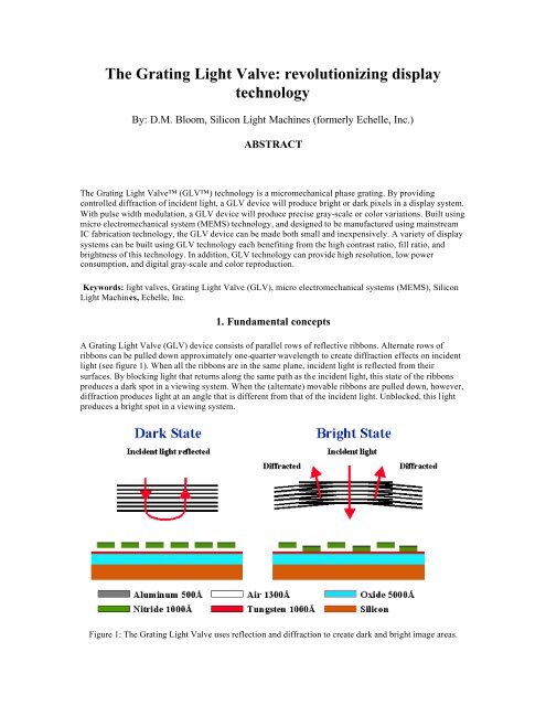
A <strong>Grating</strong> <strong>Light</strong> <strong>Valve</strong> (GLV) device consists of parallel rows of reflective ribbons. Alternate rows of<br />
ribbons can be pulled down approximately one-quarter wavelength to create diffraction effects on incident<br />
light (see figure 1). When all the ribbons are in the same plane, incident light is reflected from their<br />
surfaces. By blocking light that returns along the same path as the incident light, this state of the ribbons<br />
produces a dark spot in a viewing system. When the (alternate) movable ribbons are pulled down, however,<br />
diffraction produces light at an angle that is different from that of the incident light. Unblocked, this light<br />
produces a bright spot in a viewing system.<br />
Figure 1: <strong>The</strong> <strong>Grating</strong> <strong>Light</strong> <strong>Valve</strong> uses reflection and diffraction to create dark and bright image areas.
If an array of such GLV elements is built, and subdivided into separately controllable picture elements, or<br />
pixels, then a white-light source can be selectively diffracted to produce an image of monochrome bright<br />
and dark pixels. By making the ribbons small enough, pixels can be built with multiple ribbons producing<br />
greater image brightness. If the up and down ribbon switching state can be made fast enough, then<br />
modulation of the diffraction can produce many gradations of gray and/or colors.<br />
<strong>The</strong>re are several means for <strong>display</strong>ing color images using GLV devices. <strong>The</strong>se include color filters with<br />
multiple light valves, field sequential color, and sub-pixel color using "tuned" diffraction gratings.<br />
<strong>The</strong>se are the fundamental concepts involved in GLV design. Now let’s examine a practical method for<br />
manufacturing GLV devices.<br />
2. Building the GLV device<br />
<strong>The</strong> following describes the materials, dimensions and packaging of a GLV device capable of<br />
implementing a high-resolution <strong>display</strong>. <strong>The</strong> entire GLV device is designed to be built using mainstream IC<br />
fabrication <strong>technology</strong> (e.g. photolithographic masking, deposition, etching, metalization, etc.) to create the<br />
micro electromechanical systems (MEMS) that make up the GLV device. <strong>The</strong> GLV ribbons are built using<br />
silicon nitride, then coated with a very thin layer of aluminum (see figure 2). By making the aluminum<br />
layer very thin, one avoids some of the surface roughness that otherwise scatters the light reducing the<br />
contrast ratio.<br />
Figure 2: Build using IC fabrication <strong>technology</strong>, the <strong>Grating</strong> <strong>Light</strong> <strong>Valve</strong> consists of pairs of fixed and<br />
movable ribbons located approximately a quarter wavelength above a silicon dioxide layer.
In one implementation which Silicon <strong>Light</strong> Machines has built, the ribbon lengths are 20 µm, and the<br />
ribbon pitch is 5 µm. <strong>The</strong> pull-down distance is approximately 1300 Angstroms, or approximately onequarter<br />
wavelength of green light. With these dimensions, a set of four ribbons (two fixed and two<br />
movable) produces a 20 µm square pixel (see figure 3).<br />
Figure 3: A single pixel consists of a pair of fixed and a pair of movable ribbons.<br />
<strong>The</strong> "up" position of the ribbons is maintained by the tensile stress of the silicon nitride material. With no<br />
other forces applied, the ribbons will naturally "snap back" into an upward position. By integrating<br />
electrodes below the ribbons, and applying different voltages to the ribbons and the bottom electrodes, an<br />
electrostatic attraction force will pull the movable ribbons downward. <strong>The</strong> deflection distance is determined<br />
during manufacture.<br />
<strong>The</strong> basic GLV pixel is defined using a simple, 2-mask IC process. Silicon <strong>Light</strong> Machines has built<br />
devices using only 7 masks. In general, the more masks needed to manufacture an IC, the higher the initial<br />
cost. And, each additional masking step has a negative impact on yield (i.e. the percentage of good versus<br />
faulty components). Thus, the simple GLV design should provide lower initial costs and higher yields<br />
compared with light-valve technologies that require more complex manufacturing. When the GLV device<br />
is finished and tested, a clear glass lid is fixed above the ribbons area sealing in a dry nitrogen environment<br />
for pressure equalization and to prevent oxidation. As shown in figure 4, additional electronic driver and<br />
control logic is built into a complete, lightvalve, multi-chip module.
Figure 4: <strong>The</strong> packaged GLV subsystem can include additional electronic interface circuits for higher<br />
integration and lower cost.<br />
Having examined this blending of MEMS and IC technologies, let’s see how this GLV device is controlled,<br />
and how it performs.<br />
3. Controlling the GLV device<br />
To control a GLV-based device, one simply directs the up and down ribbon movement of this two-state<br />
<strong>technology</strong>. As mentioned previously, the ribbons will naturally assume the up state. To pull them down,<br />
one must apply a voltage difference (e.g. the switch-down voltage, V2) between the movable ribbons and<br />
bottom electrodes. Interestingly, the ribbons maintain their down state even as the voltage differential is<br />
reduced. Thus, one can pull the ribbon down with a switch-down voltage (V2), and maintain that state with<br />
bias voltage, Vb, such that V1
Figure 5: To switch a ribbon down requires a voltage differential of V2 volts or more between the ribbon<br />
and a bottom electrode. <strong>The</strong> ribbon will remain down until the voltage differential falls below V1 volts.<br />
This ribbon hysteresis offers mechanical memory and zero-power pixel-state retention. Switching time is<br />
approximately 20 nanoseconds.<br />
<strong>The</strong> up and down ribbon switching occurs very quickly. <strong>The</strong> GLV device described here switches in 20<br />
nanoseconds. That is roughly a million times faster than conventional LCD <strong>display</strong> devices, and about 1000<br />
times faster than another light-valve <strong>technology</strong> (i.e. Texas Instruments DMD micro-mirror <strong>technology</strong>).<br />
<strong>The</strong> reasons for the high speed are the small size and mass, and small excursion, of the GLV ribbons. This<br />
high-speed switching offers several benefits. At these speeds, it is easier to streamline drive electronics and<br />
to simplify the memory requirements. <strong>The</strong>re is no need to provide buffers or delay functions to complement<br />
the mismatch in speeds between electronic devices and this MEMS device.<br />
Another speed advantage is the ability to modulate, over a wide range, the time ratio of up-to-down states<br />
(or dark and bright states) which produces the effect of shades of gray or color variations. GLV switching<br />
speeds make it easy to implement an 8-bit or greater gray scale, and are fast enough to support colors and<br />
grays over a 1000-to-1 dynamic range. This is much broader gray and color accuracy than is produced<br />
using LCD <strong>technology</strong>, for example.<br />
<strong>The</strong> combination of speed and mechanical memory (e.g. ribbon hysteresis) make controlling the GLV<br />
device very simple. An elegantly simple row and column addressing scheme can be used, and passive<br />
matrix (rather than the more complex active matrix) pixel control is all that is required. This eliminates the<br />
need for any transistors in the GLV array itself, greatly simplifying the manufacturing process. <strong>The</strong> GLV<br />
device thus lends itself to an easy interface to other <strong>display</strong> system electronics.<br />
Contrast ratios, fill ratios and optical efficiencies are important metrics for distinguishing among various<br />
<strong>display</strong> technologies. High contrast ratios provide crisper images. A GLV system we built using relatively
inexpensive optics exhibits a contrast ratio of better than 200-to-1. Fill ratios — the ratio of optically active<br />
area to total pixel area — is already better than typical LCDs. In a prototype GLV array we built using<br />
mature 1.25 micron design rules, we achieved fill ratios of 67.5 percent compared with 60 percent for<br />
LCDs. Using more modern, smaller, design rules, fill ratios of 80 percent are expected.<br />
Finally, optical efficiency for reflective devices is naturally higher than that for transmissive devices. In a<br />
typical GLV prototype, where the optical system collects +/- 1 order of diffraction, about 81 percent of the<br />
incident light can be collected in the bright state. This makes for brighter images compared with other<br />
technologies when operated at comparable power consumption levels.<br />
4. Applying the GLV <strong>technology</strong><br />
In general, the GLV device can be used to build a relatively simple <strong>display</strong> system (see figure 6.) Video<br />
input is format converted and then input to a digital driver. <strong>The</strong> latter interfaces directly with the GLV<br />
device. <strong>Light</strong> is diffracted by the GLV device into an eyepiece for virtual <strong>display</strong>, or into an optical system<br />
for image projection onto a screen.<br />
Figure 6: A GLV subsystem provides a simple interface to upstream electronics.
One way of reproducing color images is by using different ribbon pitch to create a red-green-blue pixel<br />
"triad" instead of the monochrome pixel described earlier (see figure 7). In such a system, white light is<br />
introduced at an angle slightly off-axis to the GLV device. In essence, the red area, having the widest pitch,<br />
refracts red light normal to the GLV plane while green and blue light is refracted at other angles. <strong>The</strong> green<br />
and blue areas, having narrower pitch, do the same for green and blue light, respectively. Color is produced<br />
by reducing the slit width to allow only a limited bandwidth about each of the primary colors to be selected.<br />
Figure 7: By using different spacing between ribbons, one can create color-oriented sub-pixels.<br />
In a frame-sequential projection system (figure 8) a white light source is filtered sequentially (by a spinning<br />
red-green-blue filter disk, for instance). By synchronizing the image data stream’s red, green and blue pixel<br />
data with the appropriate filtered source light, combinations of red, green and blue diffracted light is<br />
directed to the projector lens. In this system, as shown, a turning mirror is used both to direct light onto the<br />
GLV device, and as an optical stop blocking reflected light.
Figure 8: A simple color <strong>display</strong> can be built using a single light source, single GLV, and rotating RGB<br />
filter disk.<br />
An even simpler, handheld, color <strong>display</strong> device (see figure 9) uses three LED sources (red, green and<br />
blue). A single GLV device diffracts the appropriate incident primary -color light to reproduce the color<br />
pixel information sent to the controller board.<br />
Figure 9: An even simpler color <strong>display</strong> can be built with 3 LEDs (RGB) and a single GLV
A more elaborate and accurate color projection system can be build using three GLV devices. By passing<br />
the source’s white light through dichroic filters, red, blue and green light are incident on three separate<br />
GLV devices. Diffracted light is collected and directed through the optical system to a viewing screen. This<br />
represents a much smaller and lower-cost solution, say, to the three-tube projection systems now used for<br />
large-screen projection of PC images and videos. An implementation scheme (see figure 10), shows the<br />
light source, optical components, and three-GLV module.<br />
Figure 10: A three-GLV color <strong>display</strong> solution is shown for a large-screen projector.<br />
5. Comparing the GLV<br />
To succeed as an alternative to existing <strong>display</strong> technologies, GLV <strong>technology</strong> must demonstrate some<br />
compelling benefits, and it does. Compared to its closest alternative — micro-mirror light valve <strong>technology</strong><br />
— the GLV device is much simpler to fabricate, requiring only 7 mask steps. GLV devices use smaller,<br />
lighter, mechanical structures that move through smaller excursions than alternative light-valve<br />
technologies. Hence, it is faster, requires less external memory and no transistors in the MEMS array.<br />
Several orders of magnitude faster than conventional LCDs and other light-valve technologies, GLV<br />
<strong>technology</strong> matches much more closely the speeds of its electronic interface components. As a result, the<br />
interface is simpler. GLV speeds also provide for higher gray scale and color variation accuracy. For<br />
example, a GLV device can be used to build a 10-bit -per-pixel, high-resolution <strong>display</strong>, compared with 8-<br />
bit-per-pixel, LCD <strong>display</strong>s.
Because GLV devices are built using mainstream IC fabrication <strong>technology</strong>, ribbon dimensions are easily<br />
scaled allowing the production of smaller, lower-cost, devices with higher resolution and fill ratios.<br />
<strong>The</strong> GLV <strong>technology</strong>’s MEMS architecture is exhibiting very encouraging reliability. Early experiments<br />
have shown no ribbon fatigue after 210 billion ribbon switching cycles. This is equivalent to a television<br />
<strong>display</strong> system running non-stop, without failure , for 15 years.<br />
With their higher optical efficiencies, GLV systems can deliver higher levels of brightness per watt of<br />
power consumed. <strong>The</strong>ir small size makes it practical to build over a million pixels in a 1.3 inch diagonal.<br />
Coupled with their mass producibility, this makes the GLV a candidate for building high-resolution, lowcost<br />
<strong>display</strong>s. And their inherent zero-power pixel-state retention make them ideal for use in small, batterypowered<br />
devices.<br />
In essence, the GLV <strong>technology</strong> promises to revolutionize <strong>display</strong> system design by making them smaller,<br />
cheaper, brighter, less power consuming, and with higher resolution.<br />
REFERENCES<br />
1. R. Apte, F. Sandejas, W. Banyai and D. Bloom, " <strong>Grating</strong> <strong>Light</strong> <strong>Valve</strong>s for High Resolution Displays,"<br />
Solid State Sensors and Actuators Workshop, June 1994<br />
2. M. Born and E. Wolfe, Principles of Optics, Pergamon Press, New York, 1959<br />
3. J. Goodman, Introduction to Fourier Optics, pp. 61-63, McGraw-Hill Book Company, San Francisco,<br />
1968<br />
4. W. Veldkamp, G. Swanson, S. Gaither, C.-L. Chen and T. Osborne, Binary Optics: a Diffraction<br />
Analysis, MIT Lincoln Laboratory, August 23, 1989<br />
5. O. Solgaard, "Integrated Semiconductor <strong>Light</strong> Modulators for Fiber-Optic and Display Applications,"<br />
Ph.D. <strong>The</strong>sis, Stanford University, 1992