Power supplies SITOP power LOGO!Power Catalog K T 10.1 2004
Power supplies SITOP power LOGO!Power Catalog K T 10.1 2004 Power supplies SITOP power LOGO!Power Catalog K T 10.1 2004
SITOP power · Standard 24 V Uninterruptible power supplies DC UPS module 6 A 9 ■ Technical specifications (continued) DC UPS module 6 Order No. 6EP1 931-2DC21 6EP1 931-2DC31 (with serial interface) 6EP1 931-2DC41 (with USB interface) Signalling 1) Normal mode Green LED (OK) and floating changeover contact "24 V DC OK/Bat" to position "24 V DC OK" 2) Buffer or battery mode (battery supplies Yellow LED (Bat) and floating changeover contact "24 V DC OK/Bat" to position "Bat" (= de-energized load on its own, or in addition to PS in position) event of overload) Alarm (buffer readiness missing or prewarning at < 20.4 V battery voltage) "Battery replacement necessary" "Battery charge > 85 %" Optional interface and software Serial interface USB interface Software Control signals On/off control signal "Remote timer start" via serial interface or USB Safety Galvanic isolation primary/secondary Protective class EMC Interference emission Red LED (Alarm) and floating changeover contact to position "Alarm" (= de-energized position). Causes for absence of buffer readiness during normal mode could be: Operating status Off or open on/off control circuit, battery module not connected, battery faulty or with reversed polarity (battery voltage < 18.5 V) or wire breakage between battery and UPS module. Scanning and thus updating of the signal every 20 s. Causes for absence of buffer readiness during buffer mode could be: Battery voltage has fallen below 20.4 V DC (= prewarning prior to switching-off by exhaustive discharge protection) as well as switchingoff of battery because of overload, short-circuit, exhaustive discharge protection or expired buffer time. The Red LED then goes off. Red LED (Alarm) flashes at 0.25 Hz and floating changeover contact (Alarm) switches at approx. 0.25 Hz Green LED (Bat > 85 %) and floating NO contact closed (de-energized position = open) Only with 6EP1 931-2DC31 Output of all signals, and receipt of signal "Remote timer start". Techn. design: PC-compatible. 8N1 send and receive, 9600 baud, 8 data bits, 1 stop bit, no parity bit. Required connection to PC: 1 : 1 continuous 9-pole SUB D extension cable (male/female), only pin 2 (RXD), pin 3 (TDX) and pin 7 (RTS) are required. Only with 6EP1 931-2DC41 Output of all signals, and receipt of signal "Remote timer start". Techn. design: Specification 2.0 with full speed, i.e. 2 Mbit/s. Powered by DC UPS with +5 V ("self powered"). Required connection to PC: Commercially available 4-core shielded cable, 90 Ohm, max. 5 m, USB series "A" connector to PC and USB series "B" connector to DC UPS A software tool (executes under WinNT4.0, Win 2000 and WinXP) for reading and processing the signals is available on the Internet at http://www.siemens.de/sitop as a download. Further information on the interface can also be found there. By opening the control circuit (or using DIP switch on device), the buffer mode is terminated, or the battery is disconnected from the output. All other functions are retained. Starts the mains buffering for the set buffer time No Class III (ext. circuit and power supply unit: SELV voltage acc. to EN 60950 is required) RI suppression acc. to EN 55022, limit characteristic B Interference immunity Interference immunity acc. to EN 61000-6-2 Ambient conditions Ambient temperature during operation 0 to +60 °C with natural convection Transportation and storage temperature -40 to +70 °C Degree of protection (EN 60529) IP20 Humidity rating Conditions of use acc. to EN 60721, climatic class 3K3 (relative humidity 5 % to 85 % and absolute humidity 1 g/m³ to 25 g/m³; no condensation) Approvals CE CE conformity acc. to 98/336 EEC and 73/23 EEC UL / cUL UL 508 / CSA C22.2, File E197259 Mechanical specifications Connections for 24 V DC input 2 screw-type terminals for 1 to 4 mm²/17 to 11 AWG Connections for 24 V DC output 4 screw-type terminals for 1 to 4 mm²/17 to 11 AWG Connections for 24 V DC battery module 2 screw-type terminals for 1 to 4 mm²/17 to 11 AWG Connections for control circuit and signals 10 screw-type terminals for 0.5 to 2.5 mm²/20 to 13 AWG Dimensions (W x H x D) in mm 50 x 125 x approx. 125 Required clearance 50 mm above and 50 mm below the device Weight Approx. 0.4 kg (with serial or USB interface: approx. 0.45 kg) Mounting Snap-mounting on DIN rail EN 50022-35x15/7.5 1) Permissible contact rating: 60 V DC/1 A or 30 V AC/1 A. 2) "24 V DC OK" means: Voltage of power supply unit is greater than the battery connection threshold set on the DC UPS module 6. 9/8 Siemens KT10.1 · 2004
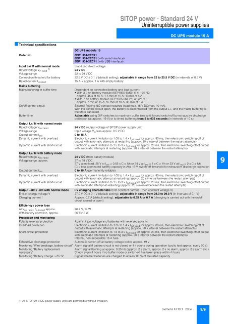
SITOP power · Standard 24 V Uninterruptible power supplies DC UPS module 15 A ■ Technical specifications DC UPS module 15 Order No. 6EP1 931-2EC21 6EP1 931-2EC31 (with serial interface) 6EP1 931-2EC41 (with USB interface) Input L+/ M with normal mode Stabilized direct voltage 1) Rated voltage V in rated 24 V DC Voltage range 22 to 29 V DC Connection threshold for battery 22.5 V DC ± 0.1 V (default setting), adjustable in range from 22 to 25.5 V DC (in intervals of 0.5 V) Rated current I in rated 15 A + approx. 1 A with empty battery Mains buffering Mains buffering or buffer time On/off control circuit Buffer time Dependent on connected battery and load current: • With 3.2 Ah battery module (6EP1935-6MD11) at +25 °C: approx. 45 s at 15 A; 1.5 min at 10 A; 13 min at 5 A • With 7 Ah battery module (6EP1935-6ME21) at +25 °C: approx. 7 min at 15 A; 15 min at 10 A; 38 min at 5 A External floating NO contact required (load max. 15 V DC/max. 10 mA). With the control circuit open, the battery is disconnected from the output L+, and the mains buffering is therefore canceled. Adjustable using DIP switches to maximum buffer time until forced switch-off by exhaustive discharge protection (at approx. 19 V) or to timed buffering from 5 to 635 seconds (in intervals of 10 s) Output L+/ M with normal mode Rated voltage V out rated 24 V DC (output voltage of SITOP power supply unit) Voltage range Input voltage V in less approx. 0.5 V DC Output current I out 0 to 15 A Dynamic current with overload Electronic current limitation to 1.05 to 1.4 x I out rated for approx. 80 ms, then electronic switching-off of output with automatic attempts at restarting (approx. 20 s interval between the restart attempts) Dynamic current with short-circuit Electronic current limitation to 1.5 to 3 x I out rated for approx. 20 ms, then electronic switching-off of output with automatic attempts at restarting (approx. 20 s interval between the restart attempts) Output L+/ M with battery mode Rated voltage V out rated 24 V DC (from battery module) Voltage range, approx. 27 to 19 V DC; 27 V at no load, 25 V at I out = 0.05 x C x 1/h or 24 V at I out = 1 x C x 1/h or 23 V at I out = 2 x C x 1/h (C = total connected battery capacity in Ah), 19 V switch-off threshold for exhaustive discharge protection Output current I out 0 to 15 A (permanently reliable) Dynamic current with overload Electronic current limitation to 1.05 to 1.4 x I out rated for approx. 80 ms, then electronic switching-off of output with automatic attempt at restarting (approx. 20 s interval between the restart attempts) Dynamic current with short-circuit Electronic current limitation to 1.5 to 3 x I out rated for approx. 20 ms, then electronic switching-off of output with automatic attempt at restarting (approx. 20 s interval between the restart attempts) Output +Bat / -Bat with normal mode I-V charging characteristic (first constant current I, then constant voltage V) End-of-charge voltage V 27.0 V DC ± 0.1 V (default setting), adjustable in range from 26.3 to 29.3 V (in intervals of 0.1 V) Charging current I Approx. 0.7 A (default setting), adjustable to 0.35 A or 0.7 A (charging is carried out with the on/off circuit closed or open) Efficiency / power loss At V out rated , I out rated approx. 96.2 %/14 W With battery operation, approx. 96 %/15 W Protection and monitoring Polarity reversal protection Against input voltage and batteries with reversed polarity Overload protection Electronic current limitation to 1.05 to 1.4 x I out rated for approx. 80 ms, then electronic switching-off of output with automatic attempts at restarting (approx. 20 s interval between the restart attempts) Short-circuit protection Electronic current limitation to 1.5 to 3 x I out rated for approx. 20 ms, then electronic switching-off of output with automatic attempts at restarting (approx. 20 s interval between the restart attempts). Internal, non-accessible 16 A fuse Exhaustive discharge protection Automatic switch-off at battery voltage below approx. 19 V Monitoring "Wire breakage, battery circuit" Alarm signal if battery circuit is not closed or if it opens during operation (cyclic test approx. every 20 s) Monitoring "Battery replacement Alarm signal flashing at approx. 0.25 Hz (approx. 2 s alarm, approx. 2 s no alarm, approx. 2 s alarm etc.). necessary" Check every 4 hours if no buffer mode or switch-off has taken place within 4 hours Monitoring "Battery charge > 85 %" Signal whether batteries are charged to at least 85 % of the rated capacity 9 1) All SITOP 24 V DC power supply units are permissible without limitation. Siemens KT10.1 · 2004 9/9
- Page 15 and 16: SITOP power · Standard 24 V Single
- Page 17 and 18: SITOP power · Standard 24 V Single
- Page 19 and 20: SITOP power · Standard 24 V Single
- Page 21 and 22: SITOP power · Standard 24 V Single
- Page 23 and 24: SITOP power · Standard 24 V Single
- Page 25 and 26: SITOP power · Standard 24 V Single
- Page 27 and 28: SITOP power · Standard 24 V Single
- Page 29 and 30: SITOP power · Standard 24 V Single
- Page 31 and 32: SITOP power · Standard 24 V Single
- Page 33 and 34: SITOP power · Standard 24 V Single
- Page 35 and 36: SITOP power · Standard 24 V Single
- Page 37 and 38: SITOP power · Standard 24 V Single
- Page 39 and 40: SITOP power · Standard 24 V Single
- Page 41 and 42: SITOP power · Standard 24 V Three-
- Page 43 and 44: SITOP power · Standard 24 V Three-
- Page 45 and 46: SITOP power · Standard 24 V Three-
- Page 47 and 48: SITOP power · Standard 24 V Three-
- Page 49 and 50: SITOP power · Standard 24 V Three-
- Page 51 and 52: SITOP power · Standard 24 V Additi
- Page 53 and 54: SITOP power · Standard 24 V Additi
- Page 55 and 56: SITOP power · Standard 24 V Additi
- Page 57 and 58: SITOP power · Standard 24 V Additi
- Page 59 and 60: SITOP power · Standard 24 V Uninte
- Page 61 and 62: SITOP power · Standard 24 V Uninte
- Page 63 and 64: SITOP power · Standard 24 V Uninte
- Page 65: SITOP power · Standard 24 V Uninte
- Page 69 and 70: SITOP power · Standard 24 V Uninte
- Page 71 and 72: SITOP power · Standard 24 V Uninte
- Page 73 and 74: SITOP power · Standard 24 V Uninte
- Page 75 and 76: SITOP power · Standard 24 V Uninte
- Page 77 and 78: SITOP power Alternative voltages 10
- Page 79 and 80: SITOP power Alternative voltages
- Page 81 and 82: SITOP power AS interface power supp
- Page 83 and 84: Power supply, type 2.4 A 7 A Order
- Page 85 and 86: SITOP power Customized 12 12/2 Desc
- Page 87 and 88: SITOP power Customized ■ FAX repl
- Page 89 and 90: LOGO!Power 13 13/2 LOGO!Power 5 V 1
- Page 91 and 92: LOGO!Power LOGO!Power 5 V Power sup
- Page 93 and 94: LOGO!Power LOGO!Power 12 V Power su
- Page 95 and 96: LOGO!Power LOGO!Power 15 V Power su
- Page 97 and 98: LOGO!Power LOGO!Power 24 V Power su
- Page 99 and 100: Technical information and configura
- Page 101 and 102: Technical information and configura
- Page 103 and 104: Technical information and configura
- Page 105 and 106: Technical information and configura
- Page 107 and 108: Technical information and configura
- Page 109 and 110: Technical information and configura
- Page 111 and 112: Technical information and configura
- Page 113 and 114: Technical information and configura
- Page 115 and 116: Technical information and configura
<strong>SITOP</strong> <strong>power</strong> · Standard 24 V<br />
Uninterruptible <strong>power</strong> <strong>supplies</strong><br />
DC UPS module 15 A<br />
■ Technical specifications<br />
DC UPS module 15<br />
Order No.<br />
6EP1 931-2EC21<br />
6EP1 931-2EC31 (with serial interface)<br />
6EP1 931-2EC41 (with USB interface)<br />
Input L+/ M with normal mode<br />
Stabilized direct voltage<br />
1)<br />
Rated voltage V in rated 24 V DC<br />
Voltage range<br />
22 to 29 V DC<br />
Connection threshold for battery 22.5 V DC ± 0.1 V (default setting), adjustable in range from 22 to 25.5 V DC (in intervals of 0.5 V)<br />
Rated current I in rated<br />
15 A + approx. 1 A with empty battery<br />
Mains buffering<br />
Mains buffering or buffer time<br />
On/off control circuit<br />
Buffer time<br />
Dependent on connected battery and load current:<br />
• With 3.2 Ah battery module (6EP1935-6MD11) at +25 °C:<br />
approx. 45 s at 15 A; 1.5 min at 10 A; 13 min at 5 A<br />
• With 7 Ah battery module (6EP1935-6ME21) at +25 °C:<br />
approx. 7 min at 15 A; 15 min at 10 A; 38 min at 5 A<br />
External floating NO contact required (load max. 15 V DC/max. 10 mA).<br />
With the control circuit open, the battery is disconnected from the output L+, and the mains buffering is<br />
therefore canceled.<br />
Adjustable using DIP switches to maximum buffer time until forced switch-off by exhaustive discharge<br />
protection (at approx. 19 V) or to timed buffering from 5 to 635 seconds (in intervals of 10 s)<br />
Output L+/ M with normal mode<br />
Rated voltage V out rated<br />
24 V DC (output voltage of <strong>SITOP</strong> <strong>power</strong> supply unit)<br />
Voltage range<br />
Input voltage V in less approx. 0.5 V DC<br />
Output current I out<br />
0 to 15 A<br />
Dynamic current with overload<br />
Electronic current limitation to 1.05 to 1.4 x I out rated for approx. 80 ms, then electronic switching-off of<br />
output with automatic attempts at restarting (approx. 20 s interval between the restart attempts)<br />
Dynamic current with short-circuit Electronic current limitation to 1.5 to 3 x I out rated for approx. 20 ms, then electronic switching-off of output<br />
with automatic attempts at restarting (approx. 20 s interval between the restart attempts)<br />
Output L+/ M with battery mode<br />
Rated voltage V out rated<br />
24 V DC (from battery module)<br />
Voltage range, approx.<br />
27 to 19 V DC;<br />
27 V at no load, 25 V at I out = 0.05 x C x 1/h or 24 V at I out = 1 x C x 1/h or 23 V at I out = 2 x C x 1/h<br />
(C = total connected battery capacity in Ah), 19 V switch-off threshold for exhaustive discharge protection<br />
Output current I out<br />
0 to 15 A (permanently reliable)<br />
Dynamic current with overload<br />
Electronic current limitation to 1.05 to 1.4 x I out rated for approx. 80 ms, then electronic switching-off of<br />
output with automatic attempt at restarting (approx. 20 s interval between the restart attempts)<br />
Dynamic current with short-circuit Electronic current limitation to 1.5 to 3 x I out rated for approx. 20 ms, then electronic switching-off of output<br />
with automatic attempt at restarting (approx. 20 s interval between the restart attempts)<br />
Output +Bat / -Bat with normal mode I-V charging characteristic (first constant current I, then constant voltage V)<br />
End-of-charge voltage V 27.0 V DC ± 0.1 V (default setting), adjustable in range from 26.3 to 29.3 V (in intervals of 0.1 V)<br />
Charging current I<br />
Approx. 0.7 A (default setting), adjustable to 0.35 A or 0.7 A (charging is carried out with the on/off<br />
circuit closed or open)<br />
Efficiency / <strong>power</strong> loss<br />
At V out rated , I out rated approx.<br />
96.2 %/14 W<br />
With battery operation, approx.<br />
96 %/15 W<br />
Protection and monitoring<br />
Polarity reversal protection<br />
Against input voltage and batteries with reversed polarity<br />
Overload protection<br />
Electronic current limitation to 1.05 to 1.4 x I out rated for approx. 80 ms, then electronic switching-off of<br />
output with automatic attempts at restarting (approx. 20 s interval between the restart attempts)<br />
Short-circuit protection<br />
Electronic current limitation to 1.5 to 3 x I out rated for approx. 20 ms, then electronic switching-off of output<br />
with automatic attempts at restarting (approx. 20 s interval between the restart attempts).<br />
Internal, non-accessible 16 A fuse<br />
Exhaustive discharge protection<br />
Automatic switch-off at battery voltage below approx. 19 V<br />
Monitoring "Wire breakage, battery circuit" Alarm signal if battery circuit is not closed or if it opens during operation (cyclic test approx. every 20 s)<br />
Monitoring "Battery replacement<br />
Alarm signal flashing at approx. 0.25 Hz (approx. 2 s alarm, approx. 2 s no alarm, approx. 2 s alarm etc.).<br />
necessary"<br />
Check every 4 hours if no buffer mode or switch-off has taken place within 4 hours<br />
Monitoring "Battery charge > 85 %" Signal whether batteries are charged to at least 85 % of the rated capacity<br />
9<br />
1) All <strong>SITOP</strong> 24 V DC <strong>power</strong> supply units are permissible without limitation.<br />
Siemens KT<strong>10.1</strong> · <strong>2004</strong> 9/9


