Power supplies SITOP power LOGO!Power Catalog K T 10.1 2004
Power supplies SITOP power LOGO!Power Catalog K T 10.1 2004 Power supplies SITOP power LOGO!Power Catalog K T 10.1 2004
Technical information and configuration Stabilized DC power supplies 14 ■ Stabilized DC power supplies (continued) Primary pulsed switched-mode power supplies: In other literature, the term SMPS (Switch Mode Power Supply) or primary switched-mode regulator is often used. Unstabilized mains G_KT01_EN_00180 Single-ended forward converter Control stabilized Vout Load Block diagram: Single-ended forward converter The primary switched-mode regulators are available in many different circuit variants. The most important basic circuits are single-ended forward converters, flyback converters, halfbridge converters, full-bridge converters, push-pull converters and resonance converters. The general principle of operation of the primary switched-mode regulator is shown in the block diagram of the single-ended forward converters. The unstabilized supply voltage is first rectified and filtered. The capacitance of the capacitor in the DC link determines the storage time of the power supply on failure of the input voltage. The voltage at the DC link is approximately 320 V DC for a 230 V supply. A single-ended converter is then supplied with this DC voltage and transfers the primary energy through a transformer to the secondary side with the help of a pulse width regulator at a high switching frequency. The switching transistor has low power losses when functioning as a switch, so that the power balance lies between > 70 % and 90 % depending on the output voltage and current. The volume of the transformer is small in comparison with a 50 Hz transformer due to the high switching frequency because the transformer size taking into account the higher switching frequency is smaller. Using modern semiconductors, switching frequencies of 100 kHz and above can be achieved. At excessively high switching frequencies, the switching losses increase, so that in each case a compromise has to be made between a high efficiency and the largest possible switching frequency. In most applications, the switching frequencies lie between 20 kHz and 250 kHz depending on the output power. The voltage from the secondary winding is rectified and filtered. The system deviation at the output is fed back to the primary circuit through an optocoupler. By controlling the pulse width (conducting phase of the switching transistor in the primary circuit), the necessary energy is transferred to the secondary circuit and the output voltage is regulated. During the non-conducting phase of the switching transistor, the transformer is demagnetized through an auxiliary winding. Just enough energy is transferred as is removed at the output. The maximum pulse width for the pulse/pause ratio for these circuits is < 50 %. Advantages: • Small magnetic components (transformer, storage reactor, filter) thanks to the high operating frequency • High efficiency thanks to pulse width regulation • Compact equipment units • Forced-air cooling is not necessary up to the kW range • High storage times are possible on mains failure by increasing the capacitance in the DC link • Larger input voltage range is possible Disadvantages: • High cost circuit, many active components • Higher costs for interference suppression • The mechanical design must be in accordance with HF criteria Primary switched-mode power supplies have become more and more popular over the last few years. Especially due to the small size, low weight, high efficiency and excellent price/performance ratio. Summary The most important characteristics of the circuit types described above are summarized in Table 2. Comparison criteria Input voltage range Regulation speed Storage time after power failure Circuit types Primary switchedmode Secondary switchedmode Comparison criteria for basic circuit variants Linear regulator Magnetic stabilizer Very large Medium Very small Large Medium Medium Very fast Slow Very long Long Very short Long Residual ripple Medium Medium Very low Medium Power loss Very small Small Large Very small Frame size Very small Medium Very large Large Weight Very light Medium Heavy Very heavy Interference suppression costs Very large Medium Low Medium 14/4 Siemens KT10.1 · 2004
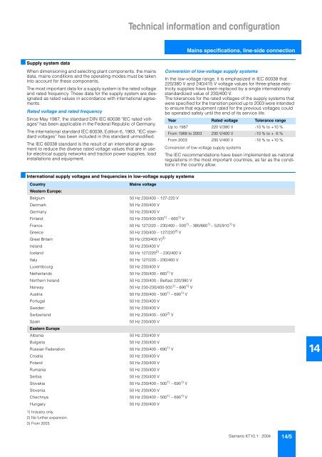
Technical information and configuration Mains specifications, line-side connection ■ Supply system data When dimensioning and selecting plant components, the mains data, mains conditions and the operating modes must be taken into account for these components. The most important data for a supply system is the rated voltage and rated frequency. These data for the supply system are designated as rated values in accordance with international agreements. Rated voltage and rated frequency Since May 1987, the standard DIN IEC 60038 "IEC rated voltages" has been applicable in the Federal Republic of Germany. The international standard IEC 60038, Edition 6, 1983, "IEC standard voltages” has been included in this standard unmodified. The IEC 60038 standard is the result of an international agreement to reduce the diverse rated voltage values that are in use for electrical supply networks and traction power supplies, load installations and equipment. Conversion of low-voltage supply systems In the low-voltage range, it is emphasized in IEC 60038 that 220/380 V and 240/415 V voltage values for three-phase electricity supplies have been replaced by a single internationally standardized value of 230/400 V. The tolerances for the rated voltages of the supply systems that were specified for the transition period up to 2003 were intended to ensure that equipment rated for the previous voltages could be operated safely until the end of its service life. Year Rated voltage Tolerance range Up to 1987 220 V/380 V -10 % to +10 % From 1988 to 2003 230 V/400 V -10 % to + 6 % From 2003 230 V/400 V -10 % to +10 % Conversion of low-voltage supply systems The IEC recommendations have been implemented as national regulations in the most important countries, as far as the conditions in the country allow. ■ International supply voltages and frequencies in low-voltage supply systems Country Mains voltage Western Europe: Belgium 50 Hz 230/400 – 127-220 V Denmark 50 Hz 230/400 V Germany 50 Hz 230/400 V Finland 50 Hz 230/400-500 1) – 660 1) V France 50 Hz 127/220 – 230/400 – 500 1) – 380/660 1) – 525/910 1) V Greece 50 Hz 230/400 – 127/220 2) V Great Britain 50 Hz (230/400 V) 3) Ireland 50 Hz 230/400 V Iceland 50 Hz 127/220 2) – 230/400 V Italy 50 Hz 127/220 – 230/400 V Luxembourg 50 Hz 230/400 V Netherlands 50 Hz 230/400 – 660 1) V Northern Ireland 50 Hz 230/400 – Belfast 220/380 V Norway 50 Hz 230-230/400-500 1) – 690 1) V Austria 50 Hz 230/400 – 500 1) – 690 1) V Portugal 50 Hz 230/400 V Sweden 50 Hz 230/400 V Switzerland 50 Hz 230/400 – 500 2) V Spain 50 Hz 230/400 V Eastern Europe Albania 50 Hz 230/400 V Bulgaria 50 Hz 230/400 V Russian Federation 50 Hz 230/400 – 690 1) V Croatia 50 Hz 230/400 V Poland 50 Hz 230/400 V Rumania 50 Hz 230/400 V Serbia 50 Hz 230/400 V Slovakia 50 Hz 230/400 – 500 1) – 690 1) V Slovenia 50 Hz 230/400 V Chechnya 50 Hz 230/400 – 500 1) – 690 1) V Hungary 50 Hz 230/400 V 14 1) Industry only. 2) No further expansion. 3) From 2003. Siemens KT10.1 · 2004 14/5
- Page 51 and 52: SITOP power · Standard 24 V Additi
- Page 53 and 54: SITOP power · Standard 24 V Additi
- Page 55 and 56: SITOP power · Standard 24 V Additi
- Page 57 and 58: SITOP power · Standard 24 V Additi
- Page 59 and 60: SITOP power · Standard 24 V Uninte
- Page 61 and 62: SITOP power · Standard 24 V Uninte
- Page 63 and 64: SITOP power · Standard 24 V Uninte
- Page 65 and 66: SITOP power · Standard 24 V Uninte
- Page 67 and 68: SITOP power · Standard 24 V Uninte
- Page 69 and 70: SITOP power · Standard 24 V Uninte
- Page 71 and 72: SITOP power · Standard 24 V Uninte
- Page 73 and 74: SITOP power · Standard 24 V Uninte
- Page 75 and 76: SITOP power · Standard 24 V Uninte
- Page 77 and 78: SITOP power Alternative voltages 10
- Page 79 and 80: SITOP power Alternative voltages
- Page 81 and 82: SITOP power AS interface power supp
- Page 83 and 84: Power supply, type 2.4 A 7 A Order
- Page 85 and 86: SITOP power Customized 12 12/2 Desc
- Page 87 and 88: SITOP power Customized ■ FAX repl
- Page 89 and 90: LOGO!Power 13 13/2 LOGO!Power 5 V 1
- Page 91 and 92: LOGO!Power LOGO!Power 5 V Power sup
- Page 93 and 94: LOGO!Power LOGO!Power 12 V Power su
- Page 95 and 96: LOGO!Power LOGO!Power 15 V Power su
- Page 97 and 98: LOGO!Power LOGO!Power 24 V Power su
- Page 99 and 100: Technical information and configura
- Page 101: Technical information and configura
- Page 105 and 106: Technical information and configura
- Page 107 and 108: Technical information and configura
- Page 109 and 110: Technical information and configura
- Page 111 and 112: Technical information and configura
- Page 113 and 114: Technical information and configura
- Page 115 and 116: Technical information and configura
- Page 117 and 118: Technical information and configura
- Page 119 and 120: Technical information and configura
- Page 121 and 122: Dimension drawings 15 SITOP power N
- Page 123 and 124: Dimension drawings SITOP power Sing
- Page 125 and 126: Dimension drawings SITOP power Sing
- Page 127 and 128: Dimension drawings SITOP power Sing
- Page 129 and 130: Dimension drawings SITOP power Addi
- Page 131 and 132: Dimension drawings SITOP power Unin
- Page 133 and 134: Dimension drawings SITOP power Alte
- Page 135 and 136: Dimension drawings LOGO!Power ■ D
- Page 137 and 138: Appendix 16 16/2 SITOP contact pers
- Page 139 and 140: Appendix SITOP contact persons ■
- Page 141 and 142: Appendix SITOP contact persons ■
- Page 143 and 144: Appendix Siemens contacts worldwide
- Page 145 and 146: Appendix Indexes ■ Order No. inde
- Page 147 and 148: Appendix Customer Support Our Servi
- Page 149 and 150: Appendix Notes 16 Siemens KT10.1 ·
- Page 151 and 152: Catalogs of the Automation and Driv
Technical information and configuration<br />
Mains specifications, line-side connection<br />
■ Supply system data<br />
When dimensioning and selecting plant components, the mains<br />
data, mains conditions and the operating modes must be taken<br />
into account for these components.<br />
The most important data for a supply system is the rated voltage<br />
and rated frequency. These data for the supply system are designated<br />
as rated values in accordance with international agreements.<br />
Rated voltage and rated frequency<br />
Since May 1987, the standard DIN IEC 60038 "IEC rated voltages"<br />
has been applicable in the Federal Republic of Germany.<br />
The international standard IEC 60038, Edition 6, 1983, "IEC standard<br />
voltages” has been included in this standard unmodified.<br />
The IEC 60038 standard is the result of an international agreement<br />
to reduce the diverse rated voltage values that are in use<br />
for electrical supply networks and traction <strong>power</strong> <strong>supplies</strong>, load<br />
installations and equipment.<br />
Conversion of low-voltage supply systems<br />
In the low-voltage range, it is emphasized in IEC 60038 that<br />
220/380 V and 240/415 V voltage values for three-phase electricity<br />
<strong>supplies</strong> have been replaced by a single internationally<br />
standardized value of 230/400 V.<br />
The tolerances for the rated voltages of the supply systems that<br />
were specified for the transition period up to 2003 were intended<br />
to ensure that equipment rated for the previous voltages could<br />
be operated safely until the end of its service life.<br />
Year Rated voltage Tolerance range<br />
Up to 1987 220 V/380 V -10 % to +10 %<br />
From 1988 to 2003 230 V/400 V -10 % to + 6 %<br />
From 2003 230 V/400 V -10 % to +10 %<br />
Conversion of low-voltage supply systems<br />
The IEC recommendations have been implemented as national<br />
regulations in the most important countries, as far as the conditions<br />
in the country allow.<br />
■ International supply voltages and frequencies in low-voltage supply systems<br />
Country<br />
Mains voltage<br />
Western Europe:<br />
Belgium<br />
50 Hz 230/400 – 127-220 V<br />
Denmark<br />
50 Hz 230/400 V<br />
Germany<br />
50 Hz 230/400 V<br />
Finland<br />
50 Hz 230/400-500 1) – 660 1) V<br />
France<br />
50 Hz 127/220 – 230/400 – 500 1) – 380/660 1) – 525/910 1) V<br />
Greece<br />
50 Hz 230/400 – 127/220 2) V<br />
Great Britain 50 Hz (230/400 V) 3)<br />
Ireland<br />
50 Hz 230/400 V<br />
Iceland<br />
50 Hz 127/220 2) – 230/400 V<br />
Italy<br />
50 Hz 127/220 – 230/400 V<br />
Luxembourg<br />
50 Hz 230/400 V<br />
Netherlands<br />
50 Hz 230/400 – 660 1) V<br />
Northern Ireland<br />
50 Hz 230/400 – Belfast 220/380 V<br />
Norway<br />
50 Hz 230-230/400-500 1) – 690 1) V<br />
Austria<br />
50 Hz 230/400 – 500 1) – 690 1) V<br />
Portugal<br />
50 Hz 230/400 V<br />
Sweden<br />
50 Hz 230/400 V<br />
Switzerland<br />
50 Hz 230/400 – 500 2) V<br />
Spain<br />
50 Hz 230/400 V<br />
Eastern Europe<br />
Albania<br />
50 Hz 230/400 V<br />
Bulgaria<br />
50 Hz 230/400 V<br />
Russian Federation<br />
50 Hz 230/400 – 690 1) V<br />
Croatia<br />
50 Hz 230/400 V<br />
Poland<br />
50 Hz 230/400 V<br />
Rumania<br />
50 Hz 230/400 V<br />
Serbia<br />
50 Hz 230/400 V<br />
Slovakia<br />
50 Hz 230/400 – 500 1) – 690 1) V<br />
Slovenia<br />
50 Hz 230/400 V<br />
Chechnya<br />
50 Hz 230/400 – 500 1) – 690 1) V<br />
Hungary<br />
50 Hz 230/400 V<br />
14<br />
1) Industry only.<br />
2) No further expansion.<br />
3) From 2003.<br />
Siemens KT<strong>10.1</strong> · <strong>2004</strong> 14/5


