MATERIALS AND SYSTEMS
MATERIALS AND SYSTEMS
MATERIALS AND SYSTEMS

Create successful ePaper yourself
Turn your PDF publications into a flip-book with our unique Google optimized e-Paper software.
2<br />
PART<br />
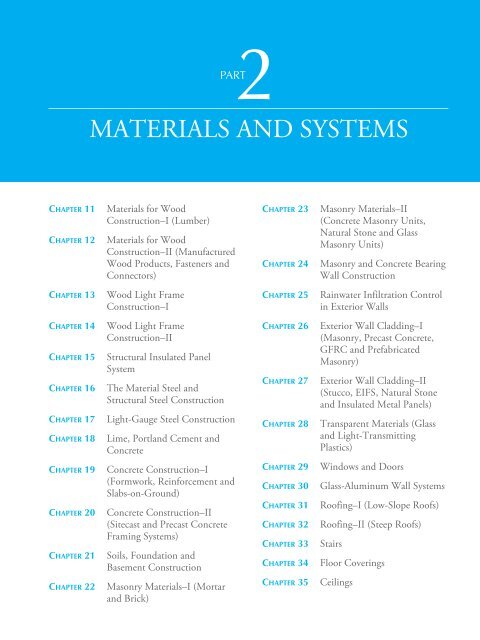
<strong>MATERIALS</strong> <strong>AND</strong> <strong>SYSTEMS</strong><br />
CHAPTER 11<br />
CHAPTER 12<br />
Materials for Wood<br />
Construction–I (Lumber)<br />
Materials for Wood<br />
Construction–II (Manufactured<br />
Wood Products, Fasteners and<br />
Connectors)<br />
CHAPTER 23<br />
CHAPTER 24<br />
Masonry Materials–II<br />
(Concrete Masonry Units,<br />
Natural Stone and Glass<br />
Masonry Units)<br />
Masonry and Concrete Bearing<br />
Wall Construction<br />
CHAPTER 13<br />
Wood Light Frame<br />
Construction–I<br />
CHAPTER 25<br />
Rainwater Infiltration Control<br />
in Exterior Walls<br />
CHAPTER 14<br />
CHAPTER 15<br />
CHAPTER 16<br />
CHAPTER 17<br />
CHAPTER 18<br />
Wood Light Frame<br />
Construction–II<br />
Structural Insulated Panel<br />
System<br />
The Material Steel and<br />
Structural Steel Construction<br />
Light-Gauge Steel Construction<br />
Lime, Portland Cement and<br />
Concrete<br />
CHAPTER 26<br />
CHAPTER 27<br />
CHAPTER 28<br />
Exterior Wall Cladding–I<br />
(Masonry, Precast Concrete,<br />
GFRC and Prefabricated<br />
Masonry)<br />
Exterior Wall Cladding–II<br />
(Stucco, EIFS, Natural Stone<br />
and Insulated Metal Panels)<br />
Transparent Materials (Glass<br />
and Light-Transmitting<br />
Plastics)<br />
CHAPTER 19<br />
CHAPTER 20<br />
CHAPTER 21<br />
CHAPTER 22<br />
Concrete Construction–I<br />
(Formwork, Reinforcement and<br />
Slabs-on-Ground)<br />
Concrete Construction–II<br />
(Sitecast and Precast Concrete<br />
Framing Systems)<br />
Soils, Foundation and<br />
Basement Construction<br />
Masonry Materials–I (Mortar<br />
and Brick)<br />
CHAPTER 29<br />
CHAPTER 30<br />
CHAPTER 31<br />
CHAPTER 32<br />
CHAPTER 33<br />
CHAPTER 34<br />
CHAPTER 35<br />
Windows and Doors<br />
Glass-Aluminum Wall Systems<br />
Roofing–I (Low-Slope Roofs)<br />
Roofing–II (Steep Roofs)<br />
Stairs<br />
Floor Coverings<br />
Ceilings
26<br />
CHAPTER<br />
Exterior Wall<br />
Cladding–I (Masonry,<br />
Precast Concrete, GFRC,<br />
and Prefabricated Masonry)<br />
CHAPTER OUTLINE<br />
26.1 MASONRY VENEER WALL ASSEMBLY—GENERAL CONSIDERATIONS<br />
26.2 BRICK VENEER wITH A CMU OR CONCRETE BACKUP WALL<br />
26.3 BRICK VENEER WITH A STEEL STUD BACKUP WALL<br />
26.4 CMU BACKUP VERSUS STEEL STUD BACKUP<br />
26.5 AESTHETICS OF BRICK VENEER<br />
26.6 PRECAST CONCRETE (PC) CURTAIN WALL<br />
26.7 CONNECTING THE PC CURTAIN WALL TO A STRUCTURE<br />
26.8 BRICK <strong>AND</strong> STONE-FACED PC CURTAIN WALL<br />
26.9 DETAILING A PC CURTAIN WALL<br />
26.10 GLASS FIBER–REINFORCED CONCRETE (GFRC) CURTAIN WALL<br />
26.11 FABRICATION OF GFRC PANELS<br />
26.12 DETAILING A GFRC CURTAIN WALL<br />
26.13 PREFABRICATED BRICK CURTAIN WALL<br />
Brick veneer buildings, illustrating one of the most widely<br />
used cladding systems in contemporary US construction,<br />
line this New York City street. Note glass-clad Bloomberg<br />
Tower (by Cesar Pelli and Associates with Schuman,<br />
Lichtenstein, Claman and Effron) in the background.<br />
(Courtesy of Emporis.)<br />
703
PART 2<br />
<strong>MATERIALS</strong> <strong>AND</strong> <strong>SYSTEMS</strong><br />
This is the first of the two chapters on exterior wall finishes, it includes masonry veneer,<br />
precast concrete, glass fiber–reinforced concrete (GFRC), and prefabricated masonry panels.<br />
Other exterior wall finishes—stucco, exterior insulation and finish systems (EIFS), stone<br />
cladding, and insulated metal panel walls—are discussed in the next chapter.<br />
26.1 MASONRY VENEER ASSEMBLY—GENERAL<br />
CONSIDERATIONS<br />
Among the most commonly used veneer walls is a single wythe of brick (generally 4 in.<br />
nominal thickness), referred to as brick veneer. The backup wall used with brick veneer may<br />
be load bearing or non–load bearing and may consist of one of the following:<br />
• Wood or light-gauge steel stud<br />
• Concrete masonry<br />
• Reinforced concrete<br />
A wood stud (or steel stud) load-bearing backup wall, Figure 26.1, is generally used in<br />
low-rise residential construction. Concrete masonry, non–load-bearing steel stud, and reinforced<br />
concrete backup walls are generally used in commercial construction. In fact, brick<br />
veneer with concrete masonry backup is the wall assembly of choice for many building<br />
types, such as schools, university campus buildings, and offices.<br />
The popularity of brick veneer lies in its aesthetic appeal and durability. A well-designed<br />
and well-constructed brick veneer wall assembly generally requires little or no maintenance.<br />
The discussion in this chapter refers to brick veneer. It can, however, be extended to include<br />
other (CMU and stone) masonry veneers with little or no change.<br />
CORRUGATED SHEET<br />
STEEL ANCHOR. Anchor is<br />
nailed to studs through airweather<br />
retarder and<br />
exterior shea thing and bent<br />
into brick course as the<br />
construction of brick veneer<br />
progresses.<br />
Wood stud back-up wall<br />
consisting of drywall interior<br />
finish (over vapor retarder, if<br />
needed)<br />
Air-weather<br />
retarder<br />
Insulation<br />
CORRUGATED SHEET STEEL<br />
ANCHOR typically used only in<br />
wood stud backed brick veneer<br />
Brick veneer<br />
1 in. air space typical for brick veneer<br />
with corruga ted sheet steel anchors.<br />
A minimum of 2 in. air space required<br />
with other anchors .<br />
Corrugated sheet steel anchor<br />
(also called corrugated tie)<br />
Minimum width = 7/8 in. and minimum<br />
thickness = 0.03 in. excluding thickness<br />
of zinc coating<br />
FIGURE 26.1 Brick veneer with wood stud backup wall. (Photo by MM.)<br />
704
Anchor must allow differential<br />
movement between veneer and<br />
back-up in horizontal direction<br />
Anchor must allow<br />
differential movement<br />
between veneer and back-up<br />
in vertical direction<br />
Wall area per anchor<br />
not to exceed 2.67 ft 2<br />
Anchor<br />
CHAPTER 26<br />
EXTERIOR WALL CLADDING<br />
18 in.<br />
maximum<br />
LITTLE OR NO MOVEMENT OF<br />
ANCHOR PERPENDICULAR TO<br />
WALL<br />
Masonry veneer<br />
Back-up wall<br />
A TYPICAL<br />
TWO-PIECE<br />
ANCHOR<br />
Air space<br />
FIGURE 26.2 Adjustability requirements in various directions of a two-piece anchor.<br />
Anchor<br />
32 in. maximum<br />
18 in.<br />
maximum<br />
FIGURE 26.3 Anchor spacing should be determined<br />
based on the lateral load and the strength<br />
of anchors. However, for a one-piece, corrugated<br />
sheet anchor or a two-piece, adjustable wire<br />
anchor (wire size W1.7), the maximum spacing<br />
allowed is as shown. W1.7 means that the crosssectional<br />
area of wire is 0.017 in. 2 (Section 18.13).<br />
Anchors are generally staggered, as shown.<br />
ANCHORS<br />
In a brick veneer assembly, the veneer is connected to the backup wall with steel anchors,<br />
which transfer the lateral load from the veneer to the backup wall. In this load transfer, the<br />
anchors are subjected to either axial compression or tension, depending on whether the wall<br />
is subjected to inward or outward pressure.<br />
The anchors must, therefore, have sufficient rigidity and allow little or no movement in<br />
the plane perpendicular to the wall. However, because the veneer and the backup will usually<br />
expand or contract at different rates in their own planes, the design of anchors must<br />
accommodate upward-downward and side-to-side movement, Figure 26.2.<br />
Anchors for a brick veneer wall assembly are, therefore, made of two pieces that engage<br />
each other. One piece is secured to the backup, and the other is embedded in the horizontal<br />
mortar joints of the veneer. An adjustable, two-piece anchor should allow the veneer to<br />
move with respect to the backup in the plane of the wall, but not perpendicular to it.<br />
An exception to this requirement is a one-piece sheet steel corrugated anchor<br />
(Figure 26.1). The corrugations in the anchor enhance the bond between the anchor and<br />
the mortar, increasing the anchor’s pullout strength. But the corrugations weaken<br />
the anchor in compression by making it more prone to buckling. A one-piece, corrugated<br />
anchor is recommended for use only in low-rise, wood, light-frame buildings<br />
in low-wind and low-seismic-risk locations.<br />
Galvanized steel is commonly used for anchors, but stainless steel is recommended<br />
where durability is an important consideration and/or where the environment<br />
is unusually corrosive.<br />
The spacing of anchors should be calculated based on the lateral load and the<br />
strength of the anchor. However, the maximum spacing for a one-piece, corrugated<br />
anchor or an adjustable, two-piece wire anchor (wire size W1.7) is limited by the code<br />
to one anchor for every 2.67 ft 2 [1]. Additionally, they should not be spaced more<br />
than 32 in. on center horizontally and not more than 18 in. vertically, Figure 26.3.<br />
AIR SPACE<br />
An air space of 2 in. (clear) is recommended for brick veneer. Thus, if there is 1 2 -in.-<br />
thick (rigid) insulation between the backup wall and the veneer, the backup and the<br />
1<br />
veneer must be spaced 3 2 in. apart so that the air space is 2 in. clear, Figure 26.4.<br />
In a narrower air space, there is a possibility that if the mortar squeezes out into the<br />
air space during brick laying, it may bridge over and make a permanent contact with<br />
the backup wall. A 2-in. air space reduces this possibility. In a wood-stud-backed wall<br />
assembly with one-piece corrugated anchors, however, a 1-in. air space is commonly<br />
used (Figure 26.1).<br />
1<br />
This dimension = 2 in. + thickness<br />
of insulation but not to exceed 4-1/2in.<br />
2 in. AIR SPACE<br />
Back-up wall<br />
Insulation,<br />
if used<br />
AIR SPACE<br />
Veneer<br />
Two-piece<br />
anchor<br />
FIGURE 26.4 A cavity width of 2 in. is recommended,<br />
except in low-rise residential buildings,<br />
where a 1-in. cavity width is common. The<br />
gap between the veneer and the backup wall<br />
1<br />
should not exceed 4 in.<br />
2<br />
705
PART 2<br />
<strong>MATERIALS</strong> <strong>AND</strong> <strong>SYSTEMS</strong><br />
The maximum distance between the veneer and backup wall is limited by the masonry<br />
1<br />
code to 4 2 in. unless the anchors are specifically engineered to withstand the compressive<br />
stress caused by the lateral load. With a large gap between the veneer and the backup wall,<br />
the anchors are more prone to buckling failure.<br />
SUPPORT FOR BRICK VENEER—SHELF ANGLES<br />
The dead load of brick veneer may be borne by the wall foundation without any support<br />
at intermediate floors up to a maximum height of 30 ft above ground. Uninterrupted,<br />
foundation-supported veneer is commonly used in a one- to three-story wood or lightgauge<br />
steel frame buildings, Figure 26.5(a). In these buildings, the air space is continuous<br />
30 ft maximum veneer height<br />
Intermediate floor<br />
Back-up wall<br />
VENEER EXTENDS<br />
CONTINUOUSLY FROM<br />
FOUNDATION TO ROOF<br />
without any intermediate<br />
support<br />
Intermediate floor<br />
Back-up wall<br />
Two-piece<br />
anchor<br />
Flashing<br />
and weep holes<br />
Mortar -<br />
capturing device<br />
Air space<br />
Mortar - capturing device<br />
Flashing and weep holes<br />
GAP between shelf<br />
angle and top of veneer,<br />
see Figure 26.6<br />
Two-piece anchor<br />
Mortar - capturing device<br />
Flashing and weep holes<br />
Gap between shelf angle<br />
and top of veneer below<br />
allows the spandrel beam<br />
to deflect freely without<br />
transferring the gravity<br />
load to veneer, see Figure<br />
26.6<br />
Two-piece anchor<br />
Mortar - capturing device<br />
Flashing and weep holes<br />
Spandrel beam<br />
SHELF ANGLE<br />
anchored to<br />
spandrel beam,<br />
see Figure 26.20<br />
Spandrel beam<br />
SHELF ANGLE<br />
anchored to<br />
spandrel beam, see<br />
Figure 26.20<br />
Gap between spandrel beam<br />
and top of back-up wall allows<br />
the beam to deflect freely<br />
without transferring gravity<br />
load to the back-up wall.<br />
Lateral support to back-up wall<br />
required here. Gap filled with<br />
insulation and treated with<br />
backer rod and sealant<br />
BRICK LEDGE<br />
Foundation<br />
Finished<br />
ground<br />
BRICK LEDGE<br />
(a) ENTIRE HEIGHT OF VENEER<br />
SUPPORTED ON FOUNDATION–<br />
a detail generally used in lowrise<br />
buildings<br />
Foundation<br />
(b) VENEER SUPPORTED AT EACH FLOOR LEVEL<br />
BY SHELF ANGLES.<br />
FIGURE 26.5 Dead load support for veneer.<br />
706
Air space<br />
Termination bar to fasten flashing to frame<br />
Brick veneer<br />
Flashing<br />
Mortar -capturing device<br />
Structural frame<br />
Weep hole<br />
FIRST COURSE OF BRICK VENEER LAID DIRECTLY<br />
OVER FLASHING <strong>AND</strong> FLASHING LAID DIRECTLY<br />
OVER SHELF ANGLE<br />
Gap based on the maximum live load<br />
deflection of spandrel beam, brick<br />
veneer's expansion and creep in columns<br />
(if any).<br />
Backer rod and low-modulus<br />
sealant (see Chapter 9)<br />
Shelf angle anchored to<br />
structural frame<br />
Shim between angle and<br />
structural frame (where<br />
needed) to extend full<br />
height of angle leg<br />
FIGURE 26.6 Schematic detail at a typical shelf angle.<br />
from the foundation to the roof level, and the entire load of the veneer bears on the foundation.<br />
A 1 2 -in. depression, referred to as the brick ledge, is commonly created in the foun-<br />
1<br />
dation to receive the first course of the veneer.<br />
In mid- and high-rise buildings, the veneer is generally supported at each floor using<br />
(preferably hot-dip galvanized) steel shelf angles (also referred to as relieving angles). Shelf<br />
angles are supported by, and anchored to, the building’s structure. In a frame structure, the<br />
shelf angles are anchored (welded or bolted) to the spandrel beams, Figure 26.5(b). In a<br />
load-bearing wall structure, the shelf angles are anchored to the exterior walls. The details<br />
of the anchorage of a shelf angle to the structure are given later in the chapter.<br />
A gap should be provided between the top of the veneer and the bottom of the shelf<br />
angle. This gap accounts for the vertical expansion of brick veneer (after construction) and<br />
the deflection of the spandrel beam under live load changes. The gap should be treated with<br />
a backer rod and sealant, Figure 26.6. The veneer may project beyond the shelf angle, but<br />
the projection should not exceed one-third of the thickness of the veneer.<br />
Shelf angles must not be continuous. A maximum length of about 20 ft is used for shelf<br />
3<br />
angles, with nearly a 8 -in. gap between adjacent lengths to provide for their expansion. The<br />
gap should ideally be at the same location as the vertical expansion joints in the veneer.<br />
NOTE<br />
Brick Ledge<br />
A brick ledge refers to the<br />
depression in concrete foundation<br />
at the base of brick<br />
1<br />
veneer and is generally 1<br />
2<br />
in.<br />
deep, because it is formed by<br />
a 2-by lumber used as a blockout<br />
when placing concrete<br />
(Figure 26.5). The depression<br />
further prevents water intrusion<br />
into the backup wall.<br />
LINTEL ANGLES—LOOSE-LAID<br />
Whether the veneer is supported entirely on the foundation or at each floor, additional dead<br />
load support for the veneer is needed over wall openings. The lintels generally used over an<br />
opening in brick veneer are of steel (preferably hot-dip galvanized) angles, Figure 26.7.<br />
Unlike the shelf angles, lintel angles are not anchored to the building’s structural frame but<br />
are simply placed (loose) on the veneer, Figure 26.8.<br />
To allow the lintel to move horizontally relative to the brick veneer, no mortar should be<br />
placed between the lintel bearing and the brick veneer. Flashing and weep holes must be<br />
provided over lintels in exactly the same way as on the shelf angles.<br />
LOCATIONS OF FLASHINGS <strong>AND</strong> END DAMS<br />
As shown in Figure 26.7, flashings must be provided at all interruptions in the brick veneer:<br />
• At foundation level<br />
• Over a shelf angle<br />
• Over a lintel angle<br />
• Under a window sill<br />
Joints between flashings must be sealed, and all flashings must be accompanied by weep<br />
holes. The flashing should preferably project out of the veneer face to ensure that the water<br />
707
PART 2<br />
<strong>MATERIALS</strong> <strong>AND</strong> <strong>SYSTEMS</strong><br />
will drain to the outside of the veneer (Figure 26.6). Where the flashing terminates, it must be<br />
turned up (equal to the height of one brick) to form a dam to prevent water from entering the<br />
air space, Figure 26.9.<br />
FLASHING <strong>MATERIALS</strong><br />
Flashing material must be impervious to water and resistant to puncture, tear, and abrasion.<br />
Additionally, flashing must be flexible so that it can be bent to the required profile.<br />
Durability is also important because replacing failed flashing is cumbersome and expensive.<br />
Therefore, metal flashing must be corrosion resistant. Resistance to ultraviolet radiation is<br />
Back-up wall<br />
Spandrel beam<br />
Shelf angle<br />
FLASHING<br />
<strong>AND</strong> WEEP<br />
HOLES<br />
Lintel in<br />
back-up wall<br />
LINTEL<br />
ANGLE<br />
Window<br />
FLASHING<br />
<strong>AND</strong> WEEP<br />
HOLES<br />
Two-piece<br />
anchor<br />
Back-up wall<br />
FLASHING<br />
<strong>AND</strong> WEEP<br />
HOLES<br />
Spandrel<br />
beam<br />
Shelf angle<br />
FLASHING<br />
<strong>AND</strong> WEEP<br />
HOLES<br />
Foundation<br />
FIGURE 26.7 A schematic section showing the locations of shelf angles and lintel angles in a typical<br />
brick veneer wall assembly.<br />
708
The back-up wall in this building consists of<br />
metal studs with gypsum sheathing. The<br />
tape covers the joints between sheathing<br />
panels. If an air-weather retarder was used,<br />
taping of joints would be unnecessary.<br />
Lintel angle is simply placed on the veneer<br />
with no anchorage to building's structure.<br />
No mortar bed should be used under lintel<br />
bearing.<br />
Flashing<br />
No mortar<br />
under lintel<br />
angle<br />
CHAPTER 26<br />
EXTERIOR WALL CLADDING<br />
Gypsum sheathing joints taped<br />
No mortar between flashing and lintel angle,<br />
see Figure 26.6.<br />
One piece of a<br />
two-piece anchor<br />
Mason cutting the flashing<br />
after turning it over lintel angle<br />
The first course of veneer over flashing is<br />
laid without any mortar bed between bricks<br />
and flashing, see Figure 26.6.<br />
FIGURE 26.8 Lintel angles in a brick<br />
veneer wall. (Photos by MM.)<br />
also necessary because the projecting part of the flashing is exposed to the sun. Commonly<br />
used flashing materials are as follows:<br />
• Stainless sheet steel<br />
• Copper sheet<br />
• Plastics such as<br />
• Polyvinyl chloride (PVC)<br />
• Neoprene<br />
• Ethylene propylene diene monomer (EPDM)<br />
• Composite flashing consisting of<br />
• Rubberized asphalt with cross-laminated polyethylene, typically available as selfadhering<br />
and self-healing flashing<br />
• Copper sheet laminated on both sides to asphalt-saturated paper or fiberglass felt<br />
Flashing turned up<br />
to form end dams<br />
FIGURE 26.9 End dams in flashing. (Photo courtesy of Brick Industry Association, Reston, Virginia.)<br />
709
PART 2<br />
<strong>MATERIALS</strong> <strong>AND</strong> <strong>SYSTEMS</strong><br />
Open head joint<br />
as a weep hole<br />
FIGURE 26.10 Open head joints as weep holes. (Photo by MM.)<br />
Copper and stainless steel are among the most durable flashing materials. Copper’s advantage<br />
over stainless steel is its greater flexibility, which allows it to be bent to shape more easily.<br />
However, copper will stain light colored masonry because of its corrosion, which yields a<br />
greenish protective cover (patina). Copper combination flashing, consisting of a copper<br />
sheet laminated to asphalt-saturated paper, reduces its staining potential.<br />
A fairly successful flashing is a two-part flashing, comprising a self-adhering, self-healing<br />
polymeric membrane and stainless steel drip edge. The durability and rigidity of stainless<br />
steel makes a good drip edge, and the flexible, self-adhering membrane simplifies flashing<br />
installation.<br />
NOTE<br />
Weep Hole Spacing<br />
A center-to-center spacing of<br />
24 in. is generally used for<br />
weep holes when open-head<br />
joints are used. A spacing of<br />
16 in. is used with weep holes<br />
consisting of wicks or tubes.<br />
CONSTRUCTION <strong>AND</strong> SPACING OF WEEP HOLES<br />
Weep holes must be provided immediately above the flashing. There are several different<br />
ways to provide weep holes. The simplest and the most effective weep hole is an open, vertical<br />
mortar joint (open-head joint) in the veneer, Figure 26.10.<br />
To prevent insects and debris from lodging in the open-head joint, joint screens may<br />
be used. A joint screen is an L-shaped, sheet metal or plastic element, Figure 26.11(a).<br />
Its vertical leg has louvered openings to let the water out, and the horizontal leg is<br />
embedded into the horizontal mortar joint of the veneer. The joint screen has the same<br />
width as the head joints. An alternative honeycombed plastic joint screen is also available,<br />
Figure 26.11(b).<br />
3<br />
Instead of the open-head joint, wicks or plastic tubes ( 8 -in. diameter) may be used in a<br />
mortared-head joint. Wicks, which consist of cotton ropes, are embedded in head joints,<br />
Brick<br />
(a) Louvered sheet<br />
metal joint screen<br />
Brick<br />
Open head joint here<br />
Brick<br />
Brick<br />
(b) Honeycomb<br />
joint screen<br />
FIGURE 26.11 Two alternative screens used with weep holes consisting of open-head joints.<br />
710
Rope wick<br />
FIGURE 26.12 Wicks as weep holes. (Photos by MM.)<br />
Figure 26.12. They absorb water from the air space by capillary action and drain it to the outside.<br />
Their drainage efficiency is low.<br />
Plastic tubes are better than wicks, but they do not function as well as open-head joints.<br />
They are placed in head joints with a rope inside each tube. The ropes are pulled out after<br />
the veneer has been constructed. This ensures that the air spaces of the tubes are not<br />
clogged by mortar droppings.<br />
A sufficient number of weep holes must be provided for the drainage of the air space.<br />
Generally, a weep hole spacing of 24 in. is used with open-head joints; 16-in. spacing is<br />
used with wicks or tubes.<br />
MORTAR DROPPINGS IN THE<br />
AIR SPACE—MORTAR-CAPTURING DEVICE<br />
For the air space to function as an effective drainage layer, it is important to minimize mortar<br />
droppings in the air space. Excessive buildup of mortar in the air space bridges the space.<br />
Additionally, the weep holes function well only if they are not clogged by mortar droppings.<br />
Poor bricklaying practice can result in substantial accumulations of mortar on the<br />
flashing. Care in bricklaying to reduce mortar droppings is therefore essential.<br />
Additional measures must also be incorporated to keep the air space unclogged. An earlier<br />
practice was to use a 2-in.-thick bed of pea gravel over the flashing. This provides a<br />
drainage bed that allows the water to percolate to the weep holes.<br />
A better alternative is to use a mortar-capturing device in the air space immediately above<br />
the flashing. This device consists of a mesh made of polymeric strands, which trap the droppings<br />
and suspend them permanently above the weep holes, Figure 26.13. The use of a<br />
mortar-capturing device allows water in the air space to percolate freely through mortar<br />
droppings to reach the weep holes.<br />
CONTINUOUS VERTICAL EXPANSION JOINTS IN BRICK VENEER<br />
As stated in Section 9.8, brick walls expand after construction. Therefore, a brick veneer<br />
must be provided with continuous vertical expansion joints at intervals, Figure 26.14.<br />
The maximum recommended spacing for vertical expansion joints is 30 ft in the field of<br />
the wall and not more than 10 ft from the wall’s corner [2]. The joints are detailed so that<br />
sealant and backer rods replace mortar joints for the entire length of the continuous vertical<br />
expansion joint, allowing the bricks on both sides of the joint to move while maintaining a<br />
waterproof seal, Figure 26.15. The width of the expansion joint is in. (minimum) to<br />
match the width of the mortar joints.<br />
With vertical expansion joints and the gaps under shelf angles (which function as horizontal<br />
expansion joints), a brick veneer essentially consists of individual brick panels that<br />
can expand and contract horizontally and vertically without stressing the backup wall or the<br />
building’s structure.<br />
MORTAR TYPE <strong>AND</strong> MORTAR JOINT PROFILE<br />
Type N mortar is generally specified in all-brick veneer except in seismic zones, where<br />
Type S mortar may be used (see Section 22.2). A concave joint profile yields veneer with<br />
more water resistance (see Section 22.3).<br />
3<br />
8<br />
711
(a) Mortar capturing device, as installed in air space<br />
(b) Mortar capturing device with mortar droppings, which allows<br />
the water to find its way to the weep holes even with the droppings.<br />
(c) Image illustrates the relative ineffectiveness<br />
of a bed of pea gravel in air space<br />
FIGURE 26.13 Mortar-capturing device. (Photos courtesy of Mortar Net USA Ltd., producers of The Mortar Net.)<br />
Horizontal joint<br />
under shelf angle<br />
Air space<br />
Backer rod<br />
Back-up wall<br />
Vertical<br />
expansion joint<br />
Horizontal joint<br />
under shelf angle<br />
Clay brick<br />
Clay brick<br />
Sealant<br />
3/8 in. minimum<br />
FIGURE 26.14 Continuous vertical expansion joints in brick<br />
veneer. Note continuous horizontal joints under shelf angles.<br />
(Photo by MM.)<br />
FIGURE 26.15 Detail plan of a vertical expansion joint in<br />
brick veneer. This illustration is the same as Figure 9.23.<br />
712
PRACTICE QUIZ<br />
Each question has only one correct answer. Select the choice that best<br />
answers the question.<br />
1. The backup wall in a brick veneer wall assembly consists of a<br />
a. reinforced concrete wall.<br />
b. CMU wall.<br />
c. wood or steel stud wall.<br />
d. all the above.<br />
e. (b) and (c) only.<br />
2. In a brick veneer wall assembly, the wind loads are transferred<br />
directly from the veneer to the building’s structure.<br />
a. True<br />
b. False<br />
3. The anchors used to anchor the brick veneer to the backup wall<br />
are generally two-piece anchors to allow differential movement<br />
between the veneer and the backup<br />
a. in all three principal directions.<br />
b. perpendicular to the plane of the veneer.<br />
c. within the plane of the veneer.<br />
d. none of the above.<br />
4. The anchors in a brick veneer wall assembly provide<br />
a. gravity load support to both veneer and backup.<br />
b. lateral load support to both veneer and backup.<br />
c. gravity load support to the veneer.<br />
d. lateral load support to the veneer.<br />
5. The minimum required width of air space between brick veneer<br />
and CMU backup wall is<br />
a. 1 in.<br />
1<br />
b. 1 2 in.<br />
c. 2 in.<br />
d. 3 in.<br />
e. none of the above.<br />
6. The minimum width of air space generally used between brick<br />
veneer and wood stud backup wall is<br />
a. 1 in.<br />
1<br />
b. 11 2 in.<br />
c. 2 in.<br />
1<br />
d. 2 2 in.<br />
e. 3 in.<br />
7. A steel angle used to support the weight of brick veneer over an<br />
opening is called a<br />
a. Lintel angle.<br />
b. Shelf angle.<br />
c. Relieving angle.<br />
d. all the above.<br />
e. (a) or (b).<br />
8. A shelf angle must be anchored to the building’s structural frame.<br />
a. True<br />
b. False<br />
9. A lintel angle must be anchored to the building’s structural frame.<br />
a. True<br />
b. False<br />
10. In a multistory building, shelf angles are typically used at<br />
a. each floor level.<br />
b. each floor level and at midheight between floors.<br />
c. at foundation level.<br />
d. all the above.<br />
e. (a) and (c).<br />
11. For a brick veneer that bears on the foundation and continues to<br />
the top of the building without any intermediate support, the<br />
maximum veneer height is limited to<br />
a. 40 ft.<br />
b. 35 ft.<br />
c. 30 ft.<br />
d. 25 ft.<br />
e. 20 ft.<br />
12. A shelf angle in a brick veneer assembly must provide<br />
a. gravity load support to the veneer.<br />
b. lateral load support to the veneer.<br />
c. gravity load support to both veneer and backup.<br />
d. lateral load support to both veneer and backup.<br />
13. In a brick veneer assembly, flashing is required<br />
a. at foundation level.<br />
b. over a lintel angle.<br />
c. over a shelf angle.<br />
d. under a window sill.<br />
e. all the above.<br />
14. In a brick veneer assembly, weep holes are required at<br />
a. each floor level.<br />
b. each alternate floor level.<br />
c. immediately above the flashing.<br />
d. immediately below the flashing.<br />
e. 2 in. above a flashing.<br />
15. The most efficient weep hole in a brick veneer consists of a<br />
a. Wick.<br />
b. Plastic tube.<br />
c. open head joint.<br />
d. none of the above.<br />
16. A mortar capturing device in a brick veneer assembly is used<br />
a. at each floor level.<br />
b. at each alternate floor level.<br />
c. immediately above a flashing.<br />
d. immediately below a flashing.<br />
e. 2 in. above a flashing.<br />
17. In a brick veneer assembly, vertical expansion joints should be<br />
provided at a maximum distance of<br />
a. 40 ft in the field of the wall and 40 ft from a wall’s corner.<br />
b. 30 ft in the field of the wall and 30 ft from a wall’s corner.<br />
c. 30 ft in the field of the wall and 20 ft from a wall’s corner.<br />
d. 30 ft in the field of the wall and 10 ft from a wall’s corner.<br />
Answers: 1-d, 2-b, 3-c, 4-d, 5-c, 6-a, 7-a, 8-a, 9-b, 10-a, 11-c, 12-a, 13-e, 14-c, 15-c, 16-c, 17-d.<br />
713
Drywall interior finish screwed to light-gauge steel furring<br />
sections (see Figure 17.4). If painted (or unpainted) CMU<br />
interior is acceptable, drywall finish is unnecessary.<br />
Vertical reinforcement in CMU back-up wall,<br />
if required for lateral load resistance<br />
Wire anchor, see<br />
Figures 26.17(a)<br />
and 26.18<br />
Termination bar to anchor<br />
flashing to back-up wall<br />
Full bed of<br />
mortar under<br />
first CMU course<br />
Floor slab<br />
Spandrel beam<br />
Rigid insulation<br />
Mortar-capturing device<br />
Flashing<br />
Brick veneer<br />
Shelf angle at<br />
spandrel beam<br />
FIGURE 26.16 Brick veneer with CMU backup.<br />
26.2 BRICK VENEER WITH A CMU OR CONCRETE<br />
BACKUP WALL<br />
Figure 26.16 shows an overall view of a brick veneer wall assembly with a concrete masonry<br />
backup wall. The steel anchors that connect the veneer to the CMU backup wall are twopiece<br />
wire anchors. One piece is part of the joint reinforcement embedded in the CMU<br />
walls. See Figure 26.17(a). The other piece fits into this piece and is embedded into the<br />
veneer’s bed joint.<br />
Several other types of anchors used with a concrete masonry backup wall are available,<br />
such as that showns in Figure 26.17(b). Figure 26.17(c) and (d) show typical anchors used<br />
with reinforced-concrete members.<br />
In seismic regions, the use of seismic clips is recommended. A seismic clip engages a continuous<br />
wire reinforcement in brick veneer. Both the seismic clip and wire are embedded in<br />
the veneer’s bed joint. A typical seismic clip is shown in Figure 26.18. [See Figure 26.17(d)<br />
714
Joint reinforcement<br />
and looped anchor are<br />
prefabricated as onepiece<br />
Horizontal joint<br />
reinforcement<br />
Grout this cell<br />
and the one below<br />
Looped anchor<br />
This anchor fits into the loop and<br />
is embedded into veneer's bed joint<br />
The slot in this clip engages<br />
into looped anchor and holds<br />
insulation in place,<br />
see Figure 26.18<br />
(a) A typical anchor used with CMU back-up walls<br />
(b) An alternative anchor for CMU back-up walls<br />
Concrete wall<br />
Sheet metal dovetail pocket<br />
embedded in reinforced concrete<br />
member. Manufacturers provide<br />
the pocket filled with foam, which<br />
is scraped clean before installing<br />
the dovetail anchor<br />
Wire<br />
reinforcement<br />
Anchor with a<br />
seismic clip<br />
Dovetail end of anchor<br />
engages in pocket and<br />
corrugated part is<br />
embedded in veneer<br />
(c) A typical anchor for concrete back-up wall, beam or column<br />
(d) An alternative anchor for concrete back-up wall, beam or column<br />
FIGURE 26.17 Typical anchors used with CMU and concrete backup walls.<br />
715
PART 2<br />
<strong>MATERIALS</strong> <strong>AND</strong> <strong>SYSTEMS</strong><br />
CMU<br />
Air space<br />
Insulation<br />
Brick veneer<br />
Wire<br />
reinforcement<br />
maximum 3/16 in.<br />
diameter<br />
(Molded plastic)<br />
seismic clip<br />
FIGURE 26.18 A typical seismic clip.<br />
716
CHAPTER 26<br />
EXTERIOR WALL CLADDING<br />
See Chapter 31<br />
(and Reference 3)<br />
for roofing details.<br />
See Figure 26.19(b)<br />
for this detail.<br />
FIGURE 26.19 (a) A wall section through a typical multistory reinforced concrete building with<br />
brick veneer and CMU backup wall.<br />
for an alternative seismic clip.] Figures 26.19 to 26.22 show important details of brick<br />
veneer construction and a CMU backup wall.<br />
The shelf angle and lintel angles can be combined into one by increasing the depth<br />
of the spandrel beam down to the level of the window head, Figure 26.23—a strategy<br />
that is commonly used with ribbon windows and continuous brick veneer spandrels,<br />
Figure 26.24.<br />
717
Anchor connects veneer<br />
to CMU back-up wall<br />
Moisture barrier coating<br />
on exterior surface of CMU<br />
wall, if needed, see Figure<br />
26.21<br />
Rigid foam insulation<br />
(extruded polystyrene or<br />
polyisocyanurate typical)<br />
Anchor connects veneer<br />
to concrete beam<br />
Termination bar to anchor<br />
flashing to back-up<br />
Mortar-capturing device<br />
Flashing and<br />
weep holes<br />
Backer rod and sealant,<br />
see Figure 26.6<br />
Seal here<br />
Vertical reinforcement in wall (may not<br />
be needed if lateral loads are small)<br />
Drywall<br />
Steel dowels from spandrel beam<br />
Steel furring section, see Figure 17.4<br />
Steel weld plate<br />
embedded in<br />
beam<br />
Shelf angle<br />
Seal here<br />
Restraint<br />
angles on<br />
both sides of<br />
CMU wall, see<br />
Figure 26.22<br />
Lintel angle<br />
Flashing<br />
Treated wood nailer to<br />
anchor window frame<br />
Weep holes<br />
Drywall<br />
Insulate and<br />
seal gap<br />
Backer rod and sealant<br />
Ceiling<br />
CMU lintel<br />
Seal here<br />
FIGURE 26.19 (b) Detail of Figure 26.19(a).<br />
718
Plate embed. Spacing of<br />
embed depends on the load<br />
carried by shelf angle and<br />
concrete strength<br />
Spandrel beam<br />
Plate embed<br />
Weld here<br />
Space for shims that<br />
extend full height of<br />
vertical leg of shelf angle<br />
Shelf angle<br />
Weld here<br />
Shelf angle<br />
(a) Shelf angle field-welded to embeds in concrete beam<br />
Cast steel wedge insert with foam fill.<br />
The fill is removed before installing the<br />
shelf angle<br />
Cast steel<br />
wedge insert<br />
Washer<br />
Slotted hole allows<br />
field adjustment of<br />
shelf angle<br />
Shelf angle<br />
Space for shims that extend full<br />
height of vertical leg of shelf angle<br />
Shelf angle<br />
(b) Shelf angle bolted to wedge inserts in concrete beam<br />
FIGURE 26.20 Two alternative methods of anchoring a shelf angle to reinforced concrete spandrel beam.<br />
FIGURE 26.21 The exterior surface of a CMU backup wall may be treated with a water-resistant<br />
coating before constructing brick veneer. (Photo by MM.)<br />
719
Restraint<br />
angle<br />
Shelf angle<br />
Spandrel<br />
beam<br />
Restraint<br />
angle<br />
(a) Restraint angles are attached to the bottom of the spandrel<br />
beam. Spacing of restraint angles is a function of lateral load on wall.<br />
Spandrel beam<br />
Dovetail restraint anchor, whose<br />
lower (cylindrical) part is encased in<br />
a plastic tube. The upper part of<br />
the anchor engages in the dovetail<br />
slot. A CMU sash unit is used in<br />
the back-up wall to engage the<br />
tube-encased leg of the anchor in<br />
the block's groove. The groove is<br />
filled with mortar.<br />
Continuous dovetail<br />
slot in spandrel beam<br />
Groove in CMU sash<br />
unit (see Figure 23.5)<br />
Wall reinforcement<br />
(b) Dovetail anchors are an alternative to restraint angles.<br />
Again, spacing of anchors is a function of lateral load on wall.<br />
FIGURE 26.22 Two alternative methods of providing lateral load restraint at the top of a CMU<br />
backup wall. (Photos by MM.)<br />
CMU backup<br />
Cavity insulation<br />
FIGURE 26.23 (Left) With a deep<br />
spandrel beam that extends from<br />
the top of window head in the<br />
lower floor to the sill level of the<br />
window at the upper floor, the<br />
shelf angle also serves as lintel<br />
angle. (Photo by MM.)<br />
Deep beam<br />
Shelf/lintel angle<br />
FIGURE 26.24 (Right) A building<br />
with brick veneer spandrels and<br />
ribbon windows. (Photo by MM.)<br />
720
26.3 BRICK VENEER WITH<br />
A STEEL STUD BACKUP WALL<br />
CHAPTER 26<br />
EXTERIOR WALL CLADDING<br />
The construction of brick veneer with a steel stud backup wall differs from that of a CMUbacked<br />
wall mainly in the anchors used for connecting the veneer to the backup. Various<br />
types of anchors are available to suit different conditions. The anchor shown in Figure<br />
26.25 is used if the air space does not contain rigid foam insulation so that it is fastened<br />
to steel studs through exterior sheathing.<br />
The anchor shown in Figure 26.26 is used if rigid foam insulation is present in the air<br />
space. The sharp ends of the prongtype anchor pierce into the insulation (not the sheathing)<br />
and transfer lateral load to the studs without compressing the insulation.<br />
Steel stud<br />
Interior drywall<br />
Exterior<br />
sheathing<br />
(a) Anchor (with self-adhering,<br />
self-sealing tape behind, not shown)<br />
Anchor with<br />
self-adhering,<br />
self-sealing<br />
tape behind<br />
Brick veneer<br />
(b) Steel stud and<br />
brick veneer assembly<br />
Anchor<br />
Exterior sheathing<br />
Steel stud<br />
FIGURE 26.25 A typical steel stud and brick veneer assembly without cavity insulation. (Photo by MM.)<br />
Steel stud<br />
Exterior<br />
sheathing<br />
Anchor with<br />
self-adhering,<br />
self-sealing<br />
tape behind<br />
Insulation<br />
(a) Prong-type Anchor<br />
Brick veneer<br />
(b) Steel stud and<br />
brick veneer assembly<br />
FIGURE 26.26 A typical steel stud and brick veneer assembly with outside insulation. (Illustration<br />
courtesy of Hohmann and Barnard, Inc.)<br />
721
PART 2<br />
<strong>MATERIALS</strong> <strong>AND</strong> <strong>SYSTEMS</strong><br />
STEEL STUD BACKUP WALL AS INFILL<br />
WITHIN THE STRUCTURAL FRAME<br />
Figure 26.27 shows a detailed section of brick veneer applied to a steel stud backup wall<br />
with the reinforced concrete structural frame. The deflection of the spandrel beam is<br />
accommodated by providing a two-track assembly consisting of a deep-leg track and a normal<br />
track, Figure 26.28(a). The upper track of this slip assembly is fastened to the beam.<br />
The studs and the interior drywall are fastened only to the lower track, which allows the<br />
upper track to slide over the lower track.<br />
Bottom track<br />
Seal here<br />
Upper deep-leg track<br />
fastened to beam<br />
Space for beam's deflection.<br />
Fill with fiberglass insulation<br />
Lower track. Studs, interior<br />
drywall and exterior sheathing<br />
fastened to lower track<br />
FIGURE 26.27 Detail of a typical steel stud and brick veneer assembly in a reinforced concrete<br />
structure.<br />
722
Upper (deep-leg) track<br />
Lower track<br />
Deep-leg<br />
slotted track<br />
Stud<br />
(a) Double slip track assembly<br />
(b) Single slotted, slip track assembly<br />
FIGURE 26.28 Two alternative methods of providing a slip-track assembly in a steel stud backup wall (of Figure 26.27). A slotted track<br />
assembly provides a positive connection between the studs and the track.<br />
Alternatively, a single, slotted, deep-leg slip-track assembly may be used. See Figure<br />
26.28(b). The studs are loose fastened to the top track through the slots. The drywall is not<br />
fastened to the slotted track. The slotted track assembly is more economical and also provides<br />
a positive connection between the track and the studs.<br />
STEEL STUD BACKUP WALL FORWARD<br />
OF THE STRUCTURAL FRAME<br />
In low-rise buildings (one or two stories), putting the steel stud backup on the outside of<br />
the structure allows it to cover the structural frame. Thus, the studs are continuous from<br />
the bottom to the top, requiring no shelf angles, Figures 26.29 and 26.30.<br />
Slip connections must be used to connect the studs with the floor or roof so that the<br />
structural frame and the wall can move independently of each other. Two alternative<br />
means of providing slip connections are used, depending on the profile of the studs,<br />
Figure 26.31.<br />
FIGURE 26.29 In a one- or two-story building with steel stud backup wall and steel frame<br />
structure, the studs are generally continuous from the bottom to the top. The vertical continuity<br />
of studs across a floor and (or) roof also helps to reduce their size in resisting the lateral loads.<br />
(Photo by MM.)<br />
723
PART 2<br />
<strong>MATERIALS</strong> <strong>AND</strong> <strong>SYSTEMS</strong><br />
Continuous studs<br />
from foundation to<br />
the top<br />
30 ft maximum, see<br />
also Figure 26.5(a)<br />
Refer to Figure<br />
26.30(b) for the<br />
enlarged version<br />
of this detail<br />
FIGURE 26.30 (a) A typical section through a low-rise (one- or two-story) steel-frame building<br />
with a brick veneer and steel stud backup wall assembly. Brick veneer is continuous from the foundation<br />
to the underside of parapet coping.<br />
724
Firestop<br />
Pour stop<br />
Steel deck<br />
Spray-applied<br />
fire protection<br />
Brick<br />
veneer<br />
Steel stud<br />
assembly<br />
Exterior<br />
sheathing<br />
Interior drywall<br />
Ceiling<br />
FIGURE 26.30 (b) Enlarged version of detail at floor level in Figure 26.30(a).<br />
Metal deck with<br />
concrete topping<br />
Pour<br />
stop<br />
Spandrel beam<br />
Slide clip<br />
FIGURE 26.31 Two alternative methods of providing a slip connection between a steel stud backup wall and the floor/roof structure, depending<br />
on the profile of studs.<br />
725
PART 2<br />
<strong>MATERIALS</strong> <strong>AND</strong> <strong>SYSTEMS</strong><br />
A brick veneer attached to a steel stud backup wall forward of the structure can also be<br />
used in mid- and high-rise buildings. Two alternative details commonly used for buildings<br />
with ribbon windows and brick spandrels are shown in Figures 26.32 and 26.33.<br />
WEATHER RESISTANCE OF A STEEL STUD BACKUP WALL<br />
Weather resistance of exterior sheathing on steel studs may be accomplished by one of the<br />
following two means:<br />
• Using a membrane that covers the entire sheathing, such as an air-weather retarder<br />
• Using a water-resistant tape on the joints between sheathing panels<br />
FIRESTOP DETAIL<br />
Steel angle hanger<br />
Pourable<br />
firestop<br />
sealant<br />
Impaling<br />
clip<br />
Shelf<br />
angle<br />
Fiberglass insulation<br />
compressed 25 to 30%<br />
Firestop<br />
Bolted connection between hanger and shelf<br />
angle for field adjustment. Weld hanger and<br />
shelf angle after completing alignment.<br />
Brick veneer<br />
Clip angle welded<br />
to beam<br />
Spandrel<br />
beam<br />
Steel angle<br />
hanger<br />
Steel angle brace<br />
Mortar-capturing<br />
device, flashing<br />
and weep holes<br />
Spray-applied fire protection<br />
not shown for sake of clarity<br />
Bent-plate<br />
shelf angle<br />
FIGURE 26.32 Brick spandrel with steel stud backup wall. Steel studs and brick veneer bear on bent-plate shelf angle.<br />
726
Structural steel C-section<br />
Steel stud anchored to<br />
structural steel C-section<br />
Bottom<br />
track for<br />
steel studs<br />
Shelf angle welded to<br />
structural steel C-sections<br />
Structural steel C-section terminates here.<br />
Weld C-section to bent plate pourstop.<br />
Firestop<br />
Where the lateral loads are low, structural steel<br />
channels may be spaced at two or three times<br />
the spacings of steel studs.<br />
Spandrel beam<br />
Structural steel C-section terminates here<br />
bottom track<br />
FIGURE 26.33 (a) Brick spandrel with steel stud backup wall. The shelf angle is hung from structural steel channels and supports only the<br />
brick veneer. See Figure 26.33(b).<br />
727
PART 2<br />
<strong>MATERIALS</strong> <strong>AND</strong> <strong>SYSTEMS</strong><br />
Steel stud anchored<br />
to structural steel<br />
channel<br />
Structural steel<br />
channel<br />
Shelf angle<br />
FIGURE 26.33 (b) Structural frame for brick spandrel with steel stud backup wall. The shelf angle<br />
is hung from vertical structural steel channels and supports only the brick veneer. (Photos by MM.)<br />
Taped joint<br />
FIGURE 26.34 A partially taped<br />
exterior sheathing over steel<br />
studs, photographed while the<br />
taping of sheathing was in<br />
progress. (Photo by MM.)<br />
The use of a continuous membrane conceals the joints between siding panels, making it<br />
more difficult for the masons to locate the studs to which the fasteners must be anchored.<br />
With taped joints, it is easier to locate the studs, Figure 26.34.<br />
26.4 CMU BACKUP VERSUS STEEL STUD BACKUP<br />
A major benefit of a steel stud backup wall in a brick veneer assembly (as compared with<br />
a CMU backup wall) is its lighter weight. For a high-rise building, the lighter wall not<br />
only reduces the size of spandrel beams but also that of the columns and footings, yield-<br />
728
ing economy in the building’s structure. However, this benefit is accompanied by several<br />
concerns.<br />
Steel studs can deflect considerably before the bending stress in them exceeds their ultimate<br />
capacity. Brick veneer, on the other hand, deflects by a very small amount before the<br />
mortar joints open. Open mortar joints weaken the wall and also increase the probability of<br />
leakage, corroding the anchors.<br />
Thus, the steel stud backup and brick veneer assembly performs well only if the stud<br />
wall is sufficiently stiff. To obtain the necessary stiffness, the deflection of studs must be<br />
controlled to a fairly small value. In fact, the design of a steel stud backup wall to resist the<br />
lateral loads is governed not by the strength of studs but by their deflection.<br />
The Brick Industry Association (BIA) recommends that the lateral load deflection of<br />
steel studs, when used as backup for brick veneer assembly, should not exceed<br />
stud span<br />
600<br />
where the stud span is the unsupported height of studs. For example, if the height of studs<br />
(e.g., from the top of the floor to the bottom of the spandrel beam in Figure 26.7) is 10 ft,<br />
the deflection of studs under the lateral load must be less than<br />
110 * 122<br />
= 0.2 in.<br />
600<br />
Increasing the stiffness of studs increases the cost of the assembly. Another concern with<br />
steel stud backup is that the veneer is anchored to the backup only through screws that<br />
engage the threads within a light-gauge stud sheet. Over a period of time, condensation can<br />
corrode the screws and the corresponding holes in studs, making the screws come loose.<br />
Condensation is, therefore, an important concern in a steel stud–backed veneer. A more<br />
serious concern is that the anchor installer will miss the studs.<br />
By comparison with steel studs, anchoring of brick veneer to a CMU backup does not<br />
depend on screws; and hence it is more forgiving. Additionally, the anchors in a CMU<br />
backup wall are embedded in the mortar joints, and if they are made of stainless steel, their<br />
corrosion probability is extremely low.<br />
Another advantage of a CMU backup wall is its inherent stiffness. To obtain a steel stud<br />
backup wall of the same stiffness as a CMU backup wall substantially increases the cost of<br />
the stud backup.<br />
NOTE<br />
CHAPTER 26<br />
EXTERIOR WALL CLADDING<br />
Defection of a Steel Stud<br />
Wall Assembly<br />
The design criterion of deflection<br />
not exceeding span<br />
divided by 600, suggested by<br />
BIA, is the minimum requirement.<br />
For critical buildings, a<br />
more stringent deflection criterion,<br />
such as span divided by<br />
720 or span divided by 900, is<br />
recommended by some<br />
experts.<br />
Steel stud manufacturers<br />
generally provide tables for the<br />
selection of their studs to conform<br />
to the deflection criteria.<br />
26.5 AESTHETICS OF BRICK VENEER<br />
It is neither possible nor within the scope of this text to illustrate various techniques used<br />
to add visual interest to brick veneer facades. However, a few examples are provided:<br />
• Use of recessed or projected bricks in the wall, Figure 26.35.<br />
• Use of bricks of different colors or combining clay bricks with other masonry materials<br />
or cast concrete, Figure 26.36.<br />
• Warping the wall, Figure 26.37.<br />
FIGURE 26.35 Use of recessed or projected bricks with<br />
different hues. The projections must be small so that the<br />
core holes in bricks are not exposed. (Photo by MM.)<br />
729
PART 2<br />
<strong>MATERIALS</strong> <strong>AND</strong> <strong>SYSTEMS</strong><br />
Band appears<br />
as a lintel but<br />
is only decorative<br />
FIGURE 26.36 Use of precast<br />
(white) concrete bands in veneer.<br />
(Photo by MM.)<br />
FIGURE 26.37 Warped brick veneer<br />
used in Frank Gehry’s Peter B. Lewis<br />
Building, Cleveland, Ohio. (Photo by<br />
an architecture student at the<br />
University of Texas at Arlington.)<br />
PRACTICE QUIZ<br />
Each question has only one correct answer. Select the choice that best<br />
answers the question.<br />
18. A typical anchor used with brick veneer and CMU backup wall<br />
assembly consists of a<br />
a. two-piece anchor, of which one is embedded in CMU backup<br />
and the other is embedded in the veneer’s mortar joint.<br />
b. three-piece anchor, of which two are fastened to the CMU<br />
backup and the other is embedded in the veneer’s mortar joint.<br />
c. two-piece anchor, of which one is an integral part of the joint<br />
reinforcement in CMU backup and the other is embedded in<br />
the veneer’s mortar joint.<br />
d. (a) and (b).<br />
e. (a) and (c).<br />
19. When lintel angles and shelf angles are combined in the same angle<br />
in a brick veneer clad building, the angle should be treated as a<br />
a. lintel angle anchored to the structural frame of the building.<br />
b. lintel angle loose-laid over underlying veneer.<br />
c. shelf angle loose-laid over underlying veneer.<br />
d. shelf angle anchored to the structural frame of the building.<br />
20. In general, a CMU-backed brick veneer is more forgiving of<br />
construction and workmanship deficiencies than a steel<br />
stud–backed brick veneer.<br />
a. True<br />
b. False<br />
21. In a brick veneer assembly with a steel stud backup wall, the<br />
design of studs is generally governed by<br />
a. the compressive strength of studs to withstand gravity loads.<br />
b. the shortening of studs to withstand gravity loads.<br />
c. the bending strength of studs to withstand lateral loads.<br />
d. the deflection of studs to withstand lateral loads.<br />
e. any one of the above, depending on the wall.<br />
Answers: 18-e, 19-d, 20-a, 21-d.<br />
26.6 PRECAST CONCRETE (PC) CURTAIN WALL<br />
Unlike brick veneer, which is constructed brick by brick at the construction site, a precast<br />
concrete (PC) curtain wall is panelized construction. The panels are constructed off-site,<br />
under controlled conditions, and transported to the site in ready-to-erect condition, greatly<br />
reducing on-site construction time.<br />
Although the PC curtain wall system is used in all climates, it is particularly favored in<br />
harsh climates, where on-site masonry and concrete construction are problematic due to<br />
freeze hazard and slow curing rate of portland cement. Panelized construction eliminates<br />
730
scaffolding, increasing on-site workers’ safety. Because panel fabrication<br />
can be done in sheltered areas, it can be accomplished uninterrupted, with<br />
a higher degree of quality control.<br />
PC curtain walls are used for almost all building types but more often<br />
are used for mid- to high-rise hospitals, apartments, hotels, parking<br />
garages, and office buildings, Figures 26.38.<br />
PC curtain wall panels are supported on and anchored to the building’s<br />
structural frame and are hoisted in position by cranes. See Figure 26.39(a)<br />
and (b). The panels are fabricated in a precast concrete plant and transported<br />
to a construction site.<br />
The structural design of PC curtain wall panels is generally done by the<br />
panel fabricator to suit the fabrication plant’s setup and resources and to provide<br />
an economical product. A typical precast concrete plant generally has<br />
in-house structural engineering expertise.<br />
In a PC curtain wall project, an important role for the architect is to work out<br />
the aesthetic expression of the panels (shapes, size, exterior finishes, etc.). This<br />
should be done in consultation with the precast plant. A great deal of coordination<br />
between the architect, engineer of record, general contractor, precast plant,<br />
and erection subcontractor is necessary for a successful PC curtain wall project.<br />
Because of the sculptability of concrete and the assortment of possible finishes<br />
of the concrete surface (smooth, abrasive-blasted, acid-etched, etc.), PC<br />
curtain walls lend themselves to a variety of facade treatments. The use of<br />
reveals (aesthetic joints), moldings, and colored concrete further add to the<br />
design variations, Figure 26.40.<br />
PANEL SHAPES <strong>AND</strong> SIZE<br />
Another key design decision is the size, shape, and function of each panel.<br />
These include window wall panels, spandrel panels, and column covers,<br />
Figure 26.41. The panels are generally one floor high, but those spanning<br />
two or (occasionally) three floors may be used.<br />
PC wall panels are generally made as large as possible, limited only by the erection<br />
capacity of the crane, transportation limitations, and gravity load delivered<br />
by the panel to the structural frame. For structural reasons, the panels generally<br />
extend from column to column. Smaller panel sizes mean a larger number of<br />
panels, requiring a greater number of support connections, longer erection time,<br />
and, hence, a higher cost. If the scale of large panels is visually unacceptable, false<br />
joints can be incorporated in the panels, as shown in preceding images.<br />
CONCRETE STRENGTH<br />
PC curtain wall panels are removed from the form as soon as possible to allow<br />
rapid turnover and reuse of the formwork. This implies that the 28-day concrete<br />
strength should be reasonably high so that when the panel is removed<br />
from the form, it can resist the stresses to which it may be subjected during<br />
the removal and handling processes.<br />
The required concrete strength is also a function of the curtain wall’s<br />
exposure, durability requirements, shape, and size of the panels. Flat panels<br />
may require higher strength (or greater thickness) as compared to ribbed or<br />
profiled panels. Therefore, the strength of concrete must be established in<br />
consultation with the precast plant supplying the panels.<br />
The most commonly used 28-day strength of concrete for PC curtain wall<br />
panels is 5,000 psi. This relatively high strength gives greater durability,<br />
greater resistance to rainwater penetration, and an improved in-service performance.<br />
In other words, the panels are better able to resist stresses caused<br />
by the loads, building movement, and volume changes induced by thermal,<br />
creep, and shrinkage effects.<br />
For aesthetic and economic reasons, a panel may use two mixes—a face<br />
(architectural) mix and a backup (structural) mix. In this case, the two mixes<br />
should have nearly equal expansion and contraction coefficients to prevent<br />
undue bowing and warping of the panel. In other words, the strength,<br />
slump, and water-cement ratios of the two mixes should be nearly the same.<br />
Because panels are generally fabricated face down on a flat formwork, the<br />
face mix is placed first followed by the backup mix. The thickness of the face<br />
FIGURE 26.38 A typical office building with precast<br />
concrete curtain wall panels. (Photo by MM.)<br />
FIGURE 26.39 (a) A PC panel being unloaded from the<br />
delivery truck for hoisting into position by a crane.<br />
(Photo by MM.)<br />
PC panel<br />
FIGURE 26.39 (b) PC panel of Figure 26.39(a) being<br />
hoisted to its final position. (Photo by MM.)<br />
731
FIGURE 26.40 (a) Lightly abrasive blasted<br />
panels with a great deal of surface detailing.<br />
(Photo by MM.)<br />
FIGURE 26.40 (b) The part of this panel<br />
on the left side of the reveal is lightly<br />
abrasive blasted, and the right side part is<br />
medium abrasive blasted. (Photo by MM.)<br />
FIGURE 26.40 (c) Panel with exposed<br />
aggregate finish. (Photo by MM.)<br />
mix is a function of the aggregate size but should not be less than 1 in. The precaster’s experience<br />
should be relied upon in determining the thicknesses and properties of the two mixes.<br />
PANEL THICKNESS<br />
The thickness of panels is generally governed by the handling (erection) stresses rather than<br />
the stresses caused by in-service loads. A concrete cover on both sides and the two-way reinforcement<br />
in a panel generally gives a total of about 3-in. of thickness. Add to this the<br />
Structural<br />
frame<br />
Beam<br />
(a) Window wall panels<br />
Column<br />
(b) Spandrel panels<br />
Spandrel<br />
panel<br />
Structural<br />
frame<br />
Structural<br />
frame<br />
FIGURE 26.41 A few commonly<br />
used panel shapes. Panels should<br />
preferably extend from column to<br />
column so that their dead load<br />
(which is delivered through two supports<br />
only) is transferred to the beam<br />
as close to the column as possible<br />
(see Section 26.7).<br />
732<br />
(c) Spandrel and infill panels. Infill panels<br />
bear on spandrel panels (see Figure 26.46)<br />
and also function as column covers.<br />
Infill<br />
panel<br />
(d) Double-height<br />
window wall panels
thickness that will be lost due to surface treatment, such as abrasive blasting and acid etching,<br />
and the total thickness of a PC wall panel cannot be less than 4 in.<br />
However, because panel size is generally maximized, a panel thickness of less than 6 in.<br />
is rare. A thicker panel is not only stronger but is also more durable, is more resistant to<br />
water leakage, and has higher fire resistance. Greater thickness also gives greater heatstorage<br />
capacity (Chapter 5), making the panel less susceptible to heat-induced stresses.<br />
CHAPTER 26<br />
EXTERIOR WALL CLADDING<br />
MOCK-UP SAMPLE(S)<br />
For PC curtain wall projects, the architect requires the precast plant to prepare and submit<br />
for approval a sample or samples of color, texture, and finish. The mock-up panels, when<br />
approved, are generally kept at the construction site and become the basis for judgment of<br />
all panels produced by the precast plant.<br />
26.7 CONNECTING THE PC CURTAIN WALL<br />
TO A STRUCTURE<br />
The connections of PC curtain wall panels to the building’s structure are among the most<br />
critical items in a PC curtain wall project and are typically designed by the panel fabricator.<br />
Two types of connections are required in each panel:<br />
• Gravity load connections<br />
• Lateral load connection<br />
There should be only two gravity load connections, also referred to as bearing supports,<br />
per panel and should be located as near the columns as possible. The lateral load connections,<br />
also referred to as tiebacks, may be as many as needed by structural considerations,<br />
generally two or more per panel, Figure 26.42.<br />
NOTE<br />
The connection system of a PC<br />
curtain wall resembles that of<br />
brick veneer connection system<br />
and is common to all<br />
types of curtain walls. The<br />
shelf angles in brick veneer<br />
provide the gravity load connection,<br />
and the anchors<br />
between the veneer and the<br />
backup provide the lateral<br />
load connection.<br />
Steel tube embedded in panel for bearing<br />
support, see Figures 26.43 and 26.44<br />
Hardware embedded in<br />
panel for tie-back connection<br />
Leveling shims between bearing<br />
plate and panel support<br />
Bearing plate embedded<br />
in spandrel beam<br />
FLOOR-TO-FLOOR SOLID<br />
(OR WINDOW WALL) PANEL<br />
Hardware embedded in panel<br />
for tie-back connection<br />
Steel tube or wide-flange section embedded in panel for bearing support<br />
(see Figure 26.44). While the section shows bearing support above beam,<br />
it can also be placed in a block-out (pocket) in the beam, which is filled<br />
with concrete after making the connection<br />
Steel tube, wide flange section<br />
or an angle embedded in panel<br />
for bearing support<br />
Leveling shims under support<br />
Bearing plate embedded<br />
in spandrel beam<br />
Tie-back connection, see<br />
Figures 26.44 and 26.45<br />
FIGURE 26.42 Support connections for a typical floor-to-floor curtain wall panel.<br />
733
PART 2<br />
<strong>MATERIALS</strong> <strong>AND</strong> <strong>SYSTEMS</strong><br />
Steel tube<br />
Leveling bolt<br />
Leveling nut welded to tube<br />
Bearing plate<br />
Spandrel beam<br />
(a) Detail section showing bearing support of panel<br />
(c) Steel tube embedment<br />
viewed from the top<br />
Leveling nut welded to<br />
the bottom of tube<br />
(b) Steel tube embedment viewed from the bottom<br />
FIGURE 26.43 Leveling nut in a steel tube used for bearing support. (Photo by MM at a precast<br />
plant.)<br />
BEARING SUPPORTS<br />
A commonly used bearing support for the floor-to-floor panels is provided through a section<br />
of steel tube, a part of which is embedded in the panel and a part of which projects out<br />
of the panel. The projecting part rests on the (steel angle) bearing plate embedded at the<br />
edge of the spandrel beam. Dimensional irregularities, both in the panel and in the structure,<br />
require the use of leveling shims (or bolts) under bearing supports during erection.<br />
After the panels have been leveled, the bearing supports are welded to the bearing plate. The<br />
bearing support system is designed to allow the panel to move<br />
within its own plane so that the panel is not subjected to<br />
stresses induced by temperature, shrinkage, and creep effects.<br />
In place of leveling shims in a bearing support, a leveling<br />
bolt is often used, Figure 26.43. The choice between the<br />
Bearing support<br />
using W-section<br />
shims and the bolt is generally left to the preference of the<br />
precast manufacturer and the erector. Alternatives to the<br />
use of steel tube for bearing supports are steel angles or a<br />
wide-flange (I-) section, Figure 26.44.<br />
Shims under support<br />
Spandrel beam<br />
Tie back connection<br />
FIGURE 26.44 Wide-flange section used as bearing support in a PC panel.<br />
(Photo by MM.)<br />
TIEBACKS<br />
A lateral load connection (tieback) is designed to resist horizontal<br />
forces on the panel from wind and/or earthquake and<br />
due to the eccentricity of panel bearing. Therefore, it must be<br />
able to resist tension and compression perpendicular to the<br />
plane of the panel.<br />
A tieback is designed to allow movement within the<br />
plane of the panel. The connection must, however, permit<br />
734
CHAPTER 26<br />
EXTERIOR WALL CLADDING<br />
Steel tube embedded into<br />
panel for bearing support<br />
Leveling shims<br />
Coiled ferrule<br />
Steel angle bearing<br />
plate embedded in beam<br />
Coiled ferrule embedded in beam<br />
Spandrel beam<br />
Threaded rod and nut<br />
Anchor embedded in panel<br />
Clip angle with<br />
slotted holes<br />
FIGURE 26.45 A typical tieback<br />
connection that allows three-way<br />
field adjustment during panel erection<br />
in addition to in-service vertical<br />
deflection of spandrel beam and thermal<br />
expansion/contraction of panel.<br />
adjustment in all three principal directions during erection. A typical tieback is shown in<br />
Figure 26.45 (see also Figure 26.44).<br />
SUPPORT <strong>SYSTEMS</strong> FOR SP<strong>AND</strong>REL PANELS <strong>AND</strong> INFILL PANELS<br />
Support systems for a curtain wall consisting of spandrel and infill panels are shown in<br />
Figure 26.46; see also Figure 26.41(c).<br />
PANELS <strong>AND</strong> STEEL FRAME STRUCTURE<br />
PC wall panels, which create eccentric loading on the spandrel beams, create torsion in the<br />
beams. Due to the lower torsional resistance of wide-flange steel beams, PC panels used with<br />
a steel frame structure are generally designed to span from column to column and made to<br />
bear directly on them. Tiebacks, however, are connected to the spandrel beams. (Note that<br />
the rotation of the spandrel beam caused by the eccentricity of panel bearing is partially<br />
balanced by reverse rotation caused by the the floor’s gravity load on the spandrel beam.)<br />
CLEARANCE OF PANELS FROM THE STRUCTURAL FRAME<br />
The Precast/Prestressed Concrete Institute (PCI) recommends a minimum horizontal<br />
clearance of 2 in. of precast panels from the building’s structural frame.<br />
26.8 BRICK <strong>AND</strong> STONE-FACED PC CURTAIN WALL<br />
PC curtain wall panels may be faced with thin (clay) bricks at the time of casting the panels.<br />
Generally, 4 - to 1-in-thick bricks are used. They are available in various shapes, Fig-<br />
3<br />
ure 26.47. The bricks are placed in the desired pattern in the form, and the concrete is<br />
735
PART 2<br />
<strong>MATERIALS</strong> <strong>AND</strong> <strong>SYSTEMS</strong><br />
Embed for tie-back connection<br />
Embed for bearing support<br />
Embeds for tieback<br />
connection<br />
Embed for tie-back connection<br />
Stretcher<br />
Embed for<br />
bearing support<br />
Embeds for tieback<br />
connection<br />
Line of top of floor on which<br />
the panel is to be supported<br />
Three-side<br />
corner<br />
(a) A PC spandrel panel being<br />
brought into its final position.<br />
Corner<br />
(b) Support connections for an<br />
infill panel bearing on a spandrel<br />
panel, see Figure 26.41(c)<br />
Edge Corner<br />
FIGURE 26.47 A few thin clay brick<br />
shapes available.<br />
FIGURE 26.48 Rubber template form<br />
liner used with thin brick-faced panels.<br />
FIGURE 26.46 Support connections for: (a) a spandrel panel, (b) a column cover bearing on<br />
spandrel panels.<br />
placed over them. To prevent the bricks from shifting during the placing operation, a rubber<br />
template is used, within which the bricks are placed, Figure 26.48. The template aligns<br />
the bricks and allows the concrete to simulate the mortar joints.<br />
In well-designed and well-fabricated panels, it is generally difficult to distinguish<br />
between a site-constructed brick veneer wall and a brick-faced PC curtain wall. Brick-faced<br />
panels have the same advantages as other PC curtain wall panels—that is, no on-site construction<br />
and no scaffolding.<br />
Thin bricks need to be far more dimensionally uniform than full-size bricks. With<br />
full-size bricks, dimensional nonuniformity is compensated by varying the mortar<br />
thickness.<br />
Because clay bricks expand by absorbing moisture from the atmosphere (moisture<br />
expansion), thin bricks should be allowed to season for a few weeks at the precaster’s plant<br />
before being used. This reduces their inherent incompatibility with concrete, which shrinks<br />
on drying.<br />
Although moisture expansion and drying shrinkage are the major causes of incompatibilities<br />
between bricks and concrete, other differences between the two materials, such as<br />
the coefficient of thermal expansion and the modulus of elasticity, must be considered.<br />
Because of these differences, a brick-faced concrete panel is subject to bowing due to differential<br />
expansion and contraction of the face and the backup.<br />
Bowing can be reduced by increasing the stiffness of the panel. Using two layers of reinforcement<br />
is encouraged when the thickness of the panel permits. Additionally, some precasters<br />
use reverse curvature in the panels.<br />
736
The bond between concrete and bricks is obviously very important for a brick-faced<br />
concrete wall panel. The back surface of bricks used in brick-faced panels should contain<br />
grooves, ribs, or dovetail slots to develop an adequate bond. The bond between concrete<br />
and brick is measured through a shear strength test. The architect should obtain these<br />
results from the brick manufacturer before specifying them for use.<br />
The bond between concrete and bricks is also a function of how absorptive the bricks<br />
are. Bricks with excessively high or excessively low water absorption give a poor bond.<br />
Bricks with high water absorption are subjected to freeze-thaw damage.<br />
CHAPTER 26<br />
EXTERIOR WALL CLADDING<br />
STONE VENEER–FACED PC PANELS<br />
PC curtain wall panels can also be faced with (natural) stone veneer. The thickness of the<br />
veneer varies with the type of stone and the face dimensions of the veneer units. Granite<br />
1<br />
and marble veneers are recommended to be at least 1 4 in. (3 cm) thick. Limestone veneer<br />
should be at least 2 in. thick.<br />
The face dimensions of individual veneer units are generally limited to 25 ft 2 for granite<br />
and 15 ft 2 for marble or limestone. Thus, a typical PC curtain wall panel has several veneer<br />
units anchored to it.<br />
The veneer is anchored to the concrete panel using stainless steel flexible dowels, whose<br />
3 5<br />
diameter varies from 16 to 8 in. Two dowel shapes are commonly used—a U-shaped<br />
(hairpin) dowel and a pair of cross-stitch dowels, Figure 26.49. The dowels are inserted in<br />
1 1<br />
the holes drilled in the veneer. The dowel holes, which are 16 to 8 in. larger in diameter<br />
than the diameter of the dowels, are filled with epoxy or an elastic, fast-curing silicone<br />
sealant. Unfilled holes will allow water to seep in, leading to staining of the veneer and<br />
freeze-thaw damage.<br />
Because the dowels are thin and flexible, they allow relative movement between the<br />
veneer and the backup. To further improve their flexibility, rubber washers are used with<br />
the dowels at the interface of the veneer and the backup.<br />
The depth of anchor in the veneer is nearly half the veneer thickness. Their anchorage<br />
into concrete varies, depending on the type of stone and the loads imposed on the panel.<br />
There should be no bond between stone veneer and and the backup concrete to prevent<br />
bowing of the panel and cracking and staining of the veneer. To prevent the bond, a bond<br />
breaker is used between the veneer and the backup. The bond breaker is either a 6- to 10-<br />
1 1<br />
mil-thick polyethylene sheet or a 8 - to 4 -in.-thick compressible, closed-cell polyethylene<br />
foam board. Foam board is preferred because it gives better movement capability with an<br />
uneven stone surface.<br />
A PC curtain wall panel may be either fully veneered with stone or the veneer may be<br />
used only as an accent or feature strip on a part of the panel.<br />
OTHER FORM LINERS<br />
Because concrete is a moldable material, several geometric and textured patterns can be<br />
embossed on panel surface using form liners. An architect can select from a variety of standard<br />
form liners available or have them specially manufactured for a large project (Section 19.4).<br />
Hairpin shape dowel<br />
Concrete back-up<br />
Pair of cross-stitched dowels<br />
Rubber washer<br />
Bond breaker<br />
Fill space between dowel<br />
and hole with epoxy or<br />
silicone sealant.<br />
FIGURE 26.49 Two commonly used dowel anchors.<br />
Stone veneer<br />
737
PART 2<br />
<strong>MATERIALS</strong> <strong>AND</strong> <strong>SYSTEMS</strong><br />
26.9 DETAILING A PC CURTAIN WALL<br />
A typical PC curtain wall is backed by an infill steel stud wall. The stud wall provides<br />
the interior finish and includes the insulation and electrical and other utility lines.<br />
Because the backup wall is not subjected to wind loads, it needs to be designed only for<br />
incidental lateral loads from the building’s interior (generally 5 psf ). Therefore, a fairly<br />
lightweight backup wall is adequate. This contrasts with a backup stud wall in a brick<br />
veneer wall, which must be designed to resist wind loads and be sufficiently stiff to have<br />
a relatively small deflection.<br />
Figure 26.50 shows a representative detail of a PC curtain wall with a steel stud backup<br />
wall. The space between the panels and the backup wall may be filled with rigid insulation,<br />
if needed.<br />
JOINTS BETWEEN PANELS<br />
Detailing the joints between panels is also a critical aspect of a PC curtain wall project. A minimum<br />
joint width of 1 in. between panels is generally recommended. Although a single-stage<br />
joint is commonly used, the preferred method is to use a two-stage joint system, consisting<br />
PC curtain wall panel<br />
with punched window<br />
Firestop<br />
Drywall interior finish<br />
over vapor retarder<br />
Steel stud wall with fiberglass<br />
insulation in stud cavities<br />
Seal here<br />
Rigid insulation,<br />
if needed<br />
Spandrel<br />
beam<br />
Two-stage<br />
joint seal<br />
Double deep leg slip<br />
track assembly<br />
Treated wood nailer<br />
for fastening window<br />
Ceiling<br />
Drywall interior finish<br />
over vapor retarder<br />
Steel stud wall with fiberglass<br />
insulation in stud cavities<br />
FIGURE 26.50 A typical PC curtain wall (schematic) detail.<br />
738
OUTSIDE<br />
INSIDE<br />
INSIDE<br />
Provide weep holes<br />
in the outer seal<br />
OUTSIDE<br />
OUTSIDE<br />
INSIDE<br />
(c) Two-stage vertical joint<br />
Both seals applied from the outside<br />
(a) Single-stage horizontal joint<br />
(b) Two-stage horizontal joint. Both seals applied from the outside<br />
FIGURE 26.51 Treatment of joints between PC curtain wall panels.<br />
of a pair of backer rod and sealant bead combination. One backer rod and sealant bead<br />
combination is placed toward the outer surface of the joint and the other is placed toward the<br />
inner surface, Figure 26.51.<br />
The outer seal provides a weather barrier and contains weep holes. The inner seal is continuous<br />
without any openings and is meant to provide an air barrier. The air barrier must<br />
extend continuously over a panel and across the joint between panels. The provision of the air<br />
barrier and the openings in the exterior seal makes the two-stage joint system function as a<br />
rain screen (Chapter 25).<br />
Both inner and outer seals should be applied from the outside to avoid discontinuities at<br />
the spandrel beams and floor slabs. This requires a deep-stem roller to push the backer rod<br />
deep into the joint and a long-nozzle sealant gun.<br />
INSULATED, S<strong>AND</strong>WICHED PANELS<br />
PC curtain wall panels with rigid plastic foam insulation sandwiched between two layers of<br />
concrete may be used in cold regions. A sandwich panel consists of an outer layer of concrete<br />
and an inner layer of concrete, in which both layers are connected together with ties<br />
through an intermediate layer of rigid plastic foam insulation.<br />
The outer layer is a nonstructural layer, whereas the inner layer is designed to carry the<br />
entire load and transfer it to the structural frame. The panel is fabricated by first casting<br />
the concrete for the nonstructural layer. This is followed by embedding the ties and placing<br />
the insulation boards over the ties. The insulation is provided with holes so that the ties project<br />
above the insulation and are embedded in the concrete that is cast above the insulation.<br />
PRACTICE QUIZ<br />
Each question has only one correct answer. Select the choice that best<br />
answers the question.<br />
22. The strength of concrete used in precast concrete curtain walls is<br />
generally<br />
a. greater than or equal to 3,000 psi.<br />
b. greater than or equal to 4,000 psi.<br />
c. greater than or equal to 5,000 psi.<br />
d. none of the above.<br />
23. Precast concrete curtain wall panels are generally<br />
a. cast on the construction site.<br />
b. fabricated by a readymix concrete plant and transported to the<br />
construction site.<br />
c. (a) or (b).<br />
d. none of the above.<br />
24. The number of bearing supports in a precast concrete curtain wall<br />
panel must be<br />
a. one.<br />
b. two.<br />
c. three.<br />
d. four.<br />
e. between three and six.<br />
25. The structural design of precast concrete curtain wall panels is<br />
generally the responsibility of the<br />
a. structural engineer who designs the structural frame of the<br />
building in which the panels are to be used.<br />
b. structural engineer retained by the panel fabricator.<br />
c. structural engineer retained by the general contractor of the<br />
building.<br />
d. structural engineer specially retained by the owner.<br />
e. none of the above.<br />
739
PRACTICE QUIZ (Continued)<br />
26. During the erection of precast concrete curtain wall panels, the<br />
panels are leveled. The leveling of the panels is provided in the<br />
a. panels’ bearing supports.<br />
b. panels’ tieback connections.<br />
c. (a) or (b).<br />
d. (a) and (b).<br />
27. The bricks used in brick-faced concrete curtain wall panels are<br />
generally<br />
a. of the same thickness as those used in brick veneer<br />
construction.<br />
b. thicker than those used in brick veneer construction.<br />
c. thinner than those used in brick veneer construction.<br />
d. any one of the above, depending on the building.<br />
28. A bond break such as a polyethylene sheet membrane is generally<br />
used between the concrete and bricks in a brick-faced precast<br />
concrete curtain wall panel.<br />
a. True<br />
b. False<br />
29. The connection between natural stone facing and the backup<br />
concrete in a stone-faced precast concrete curtain wall panel is<br />
obtained by<br />
a. The roughness of the stone surface that is in contact with<br />
concrete.<br />
b. nonmoving steel dowels.<br />
c. flexible steel dowels.<br />
d. any one of the above.<br />
Answers: 22-c, 23-d, 24-b, 25-b, 26-a, 27-c, 28-b, 29-c.<br />
26.10 GLASS FIBER–REINFORCED CONCRETE<br />
(GFRC) CURTAIN WALL<br />
As the name implies, glass fiber–reinforced concrete (GFRC) is a type of concrete whose<br />
ingredients are portland cement, sand, glass fibers, and water. Glass fibers provide tensile<br />
strength to concrete. Unlike a precast concrete panel, which is reinforced with steel bars, a<br />
GFRC panel does not require steel reinforcing.<br />
The fibers are 1 to 2 in. long and are thoroughly mixed and randomly dispersed in the<br />
mix. The random and uniform distribution of fibers not only provides tensile strength, but<br />
also gives toughness and impact resistance to a GFRC panel. Because normal glass fibers are<br />
adversely affected by wet portland cement (due to the presence of alkalies in portland<br />
cement), the fibers used in a GFRC mix are alkali-resistant (AR) glass fibers.<br />
GFRC SKIN <strong>AND</strong> STEEL FRAME<br />
A GFRC curtain wall panel consists of three main components:<br />
• GFRC skin<br />
• Light-gauge steel backup frame<br />
• Anchors that connect the skin to the steel backup frame<br />
Of these three components, only the skin is made of GFRC, which is generally 2 - to 4 -<br />
in.-thick. The skin is anchored to a frame consisting of light-gauge (galvanized) steel members,<br />
Figure 26.52. In this combination, the GFRC skin transfers the loads to the frame,<br />
which, in turn, transfers the loads to the building’s structure. The size and spacing of backup<br />
frame members depends on the overall size of the panel and the loads to which it is subjected.<br />
1<br />
3<br />
Reveal (aesthetic joint)<br />
FIGURE 26.52 (a) The front of a large GFRC panel after light abrasive blasting. It is being lifted for<br />
storage in the fabricator’s yard. (Photo by MM.)<br />
740
FLEX ANCHORS<br />
The skin is hung 2 in. (or more) away from the face of the frame using bar anchors. The<br />
gap between the skin and the frame is essential because it allows differential movement<br />
between the skin and the frame, particularly during the period when the fresh concrete in<br />
the skin shrinks as water evaporates.<br />
3<br />
The anchors are generally 8 -in.-diameter steel bars, bent into an L-shape. To provide<br />
corrosion resistance, cadmium-plated steel is generally used for the anchors. One end of an<br />
anchor is welded to the frame, and the other end is embedded in the skin. The skin is thickened<br />
around the anchor embedment. The thickened portion of the skin is referred to as a<br />
bonding pad, Figure 26.53.<br />
The purpose of the anchors is to transfer both gravity and lateral loads from the skin to the<br />
frame. In doing so, the anchors must be fairly rigid in the plane perpendicular to the panel;<br />
that is, they should be able to transfer the loads without any deformation in the anchors.<br />
CHAPTER 26<br />
EXTERIOR WALL CLADDING<br />
The GRFC skin includes a<br />
corner return that provides<br />
a means of forming sealed<br />
joints between panels.<br />
A minimum 2 in. return is<br />
required. A larger return<br />
may be needed for a twostage<br />
joint between panels.<br />
GFRC skin<br />
Reveal (aesthetic joint)<br />
Flex<br />
anchor<br />
Bonding pad<br />
Vertical frame member<br />
PLAN OF AN L-SHAPED GFRC PANEL<br />
FIGURE 26.52 (b) The side and<br />
back of an L-shaped GFRC panel<br />
showing the supporting steel frame.<br />
(Photos by MM.)<br />
741
Flex anchor<br />
Bonding pad,<br />
see Figure 26.60<br />
Flex<br />
anchor<br />
GFRC skin<br />
Anchor<br />
welded here<br />
Bonding pad<br />
2 in.<br />
minimum<br />
gap between<br />
frame and skin<br />
Frame member<br />
FIGURE 26.53 Bonding pads and flex anchors. (Photo by MM.)<br />
FIGURE 26.54 Flexibility of flex anchors.<br />
However, the skin will experience in-plane dimensional changes due to moisture and<br />
temperature effects. The anchor must therefore have sufficient flexibility to allow these<br />
changes to occur without excessively stressing the skin. One way of achieving this goal is<br />
to flare the anchor away from the frame and to weld it to the frame member at the far<br />
end, Figure 26.54. The term flex anchor underscores the importance of anchor flexibility.<br />
PANEL SHAPES<br />
Like the precast concrete curtain wall panels, GFRC curtain wall panels can be made into<br />
different shapes, depending on the design of the building’s facade. The most commonly<br />
used panels are floor-to-floor solid panels (Figure 26.52), and window wall panels, Figure<br />
26.55 and spandrel panels. A spandrel panel is essentially a solid panel of smaller<br />
height. Because the panels can be configured in several ways for a given facade, the architect<br />
must work with the GFRC fabricator before finalizing panel shapes.<br />
2 in. minimum gap between<br />
frame and skin<br />
Opening<br />
for window<br />
Horizontal frame member<br />
Vertical frame<br />
member<br />
GFRC<br />
skin<br />
Horizontal frame<br />
member<br />
SECTION THROUGH A WINDOW WALL PANEL<br />
(Anchors not shown)<br />
FIGURE 26.55 The front and back of a typical window wall panel. (Photo by MM.)<br />
742
26.11 FABRICATION OF GFRC PANELS<br />
Figures 26.56 to 26.60 show the six-step process of fabricating a GFRC panel.<br />
• Preparing the Mold: The mold must be fabricated to the required shape, Figure 26.56.<br />
The mold generally consists of plywood, but other materials, such as steel or plastics,<br />
may be used. A form-release compound is applied to the mold before applying the<br />
GFRC mix to facilitate the panel’s removal from the mold.<br />
• Applying the Mist Coat: Before GFRC mix is sprayed on the panel, a thin cementsand<br />
slurry coat, referred to as a mist coat, is sprayed on the mold, Figure 26.57.<br />
Because the mist coat does not contain any glass fibers, it gives a smooth, even surface<br />
to the panel. The thickness of the mist coat is a function of the finish the panel<br />
1<br />
face is to receive. If the panel face is to be lightly abrasive-blasted, a 8 -in.-thick mist<br />
coat is adequate.<br />
• Applying the GFRC Mix: Soon after the mist coat is applied, GFRC mix is sprayed on<br />
the mold. See Figure 26.58(a). GFRC mix consists of (white) portland cement and<br />
sand slurry mixed with about 5% (by weight) of glass fibers. Because air may be<br />
trapped in the mix during spraying, the mix is consolidated after completing the spray<br />
application by rolling, tamping, or troweling, Figure 26.58(b).<br />
• Frame Placement: After the GFRC spray is completed, the steel backup frame is<br />
placed against the skin, leaving the required distance between the skin and the<br />
frame, Figure 26.59.<br />
• Bonding Pads: Finally, bonding pads are formed at each anchor using the same mix as<br />
that used for the skin, Figure 26.60.<br />
• Removing the Panel from the Mold and Curing: The panel (skin and frame) is generally<br />
removed from the mold 24 h after casting and subsequently cured for a number of<br />
days. Because the panel has not yet gained sufficient strength, special care is needed<br />
during the panel’s removal.<br />
CHAPTER 26<br />
EXTERIOR WALL CLADDING<br />
Plastic channel to form a reveal.<br />
The channel is removed after the<br />
skin has gained sufficient strength.<br />
FIGURE 26.56 The mold of a roof cornice panel.<br />
FIGURE 26.57 Application of mist coat. (Photo by MM.)<br />
743
FIGURE 26.58 (a) Spraying GFRC mix over the mist coat. Photo by MM. (b) Consolidating GFRC mix using a roller around bends, edges and<br />
corners. (Photo by MM.)<br />
Frame<br />
GFRC skin<br />
FIGURE 26.59 Placing a frame<br />
against the skin. (Photo by MM.)<br />
FIGURE 26.60 Making of a bonding<br />
pad (see also Figure 26.53). (Photos<br />
by MM.)<br />
744<br />
SURFACE FINISHES ON GFRC PANELS<br />
The standard finish on a GFRC panel is a light abrasive-blasted finish to remove the<br />
smoothness of the surface obtained from the mist coat. However, a GFRC panel can also be<br />
given an exposed aggregate finish, which results in a surface similar to that of a precast<br />
concrete panel.<br />
To obtain an exposed aggregate finish, the mist coat is replaced by a concrete layer, referred<br />
to as a face mix. The thickness of the face mix is about in., and the aggregate used in<br />
3<br />
1<br />
the face mix is between 16 in. and 4 in. The exposure of aggregate is obtained by abrasive<br />
blasting or acid etching.<br />
3<br />
8
26.12 DETAILING A GFRC CURTAIN WALL<br />
A GFRC panel is connected to the building’s structure in a system similar to that of a precast<br />
concrete panel. In other words, a GFRC panel requires two bearing connections and<br />
two or more tieback connections. However, because GFRC panels are much lighter than<br />
the precast concrete panels, their connection hardware is lighter.<br />
As with precast concrete curtain walls, the structural design of panels and their support<br />
connections is generally the responsibility of panel fabricator. Figures 26.61 and 26.62<br />
CHAPTER 26<br />
EXTERIOR WALL CLADDING<br />
Double track<br />
Structural steel tube<br />
Structural steel angle with leveling nut<br />
(welded to structural steel tube)<br />
provides bearing support<br />
Structural steel angle with holes<br />
for leveling bolt provides bearing<br />
support<br />
Ferrule welded to steel tube<br />
provides tie-back connection<br />
Structural<br />
steel tube<br />
Light-gauge<br />
steel members<br />
(a) Back-up frame for GFRC<br />
spandrel panel<br />
Structural steel angle<br />
for bearing support<br />
Leveling bolt<br />
Ferrule welded to steel tube<br />
provides tie-back connection<br />
Leveling<br />
nut<br />
This frame shows the use of double<br />
tracks at the top and bottom of the<br />
panel. With the use of diagonal braces,<br />
it may be possible to use only single<br />
tracks. Because frame members are<br />
welded together, a minimum thickness<br />
of 16-gauge is required of light-gauge<br />
frame members.<br />
GFRC skin<br />
Tie-back connection<br />
Block-out in<br />
spandrel beam,<br />
filled with concrete<br />
after making<br />
connections<br />
(b) Section showing connection of GFRC<br />
spandrel panel to building's structure<br />
FIGURE 26.61 Schematic details of bearing and tieback connections in a spandrel GFRC panel (see also Figures 26.62 and 26.63).<br />
745
PART 2<br />
<strong>MATERIALS</strong> <strong>AND</strong> <strong>SYSTEMS</strong><br />
show two alternative schematics for the connection of a GFRC spandrel panel to the building’s<br />
structure.<br />
Figure 26.63 shows a typical GFRC curtain wall detail. Because GFRC skin is thin,<br />
some form of water drainage system from behind the skin should be incorporated in the<br />
panels. Additionally, the space between the GFRC skin and the panel frame should be<br />
freely ventilated to prevent the condensation of water vapor. This is generally not a requirement<br />
in precast concrete curtain walls. A two-way joint sealant system may be used at panel<br />
junctions similar to that for PC curtain walls (Figures 26.50 and 26.51).<br />
Structural steel tube<br />
Structural steel angle with<br />
holes for leveling bolt provides<br />
bearing support<br />
Structural steel tube<br />
with holes for leveling<br />
bolt provides bearing<br />
support<br />
Structural steel tube with holes<br />
for leveling bolt provides bearing<br />
support<br />
Ferrule welded to steel tube<br />
provides tie-back connection<br />
Light-gauge<br />
steel members<br />
Ferrule welded to steel tube<br />
provides tie-back connection<br />
(a) Back-up frame for GFRC<br />
spandrel panel<br />
Leveling<br />
nut<br />
Leveling bolt<br />
Steel tube within frame<br />
6 in. long section of steel tube<br />
welded to pour stop<br />
This frame shows the use of double<br />
tracks at the top and bottom of the<br />
panel. With the use of diagonal braces,<br />
it may be possible to use only single<br />
tracks. Because frame members are<br />
welded together, a minimum thickness<br />
of 16-gauge is required of light-gauge<br />
frame members.<br />
GFRC skin<br />
Tie-back connection<br />
(b) Section showing connection of GFRC<br />
spandrel panel to building's structure<br />
FIGURE 26.62 Schematic details of bearing supports and tieback connections in a spandrel GFRC panel (see also Figures 26.61<br />
and 26.63).<br />
746
Aluminum sill<br />
flashing<br />
Window assembly supported on frame<br />
Extruded aluminum interior sill<br />
CHAPTER 26<br />
EXTERIOR WALL CLADDING<br />
GFRC<br />
skin<br />
Outer surface<br />
of GFRC frame<br />
Aluminum foil-backed rigid mineral<br />
wool insulation with taped joints<br />
Gypsum board on 2-1/2 in. steel studs<br />
(or on furring strips over frame members)<br />
Gap between<br />
GFRC skin<br />
and frame<br />
Gypsum board<br />
Continuous<br />
drainage to<br />
weep holes<br />
Aluminum foil-backed rigid mineral<br />
wool insulation with taped joints<br />
Spray-applied fire protection<br />
not shown for clarity<br />
Drip<br />
groove<br />
Sealant<br />
and backer rod<br />
Ceiling<br />
FIGURE 26.63 Schematic detail of an exterior wall with GFRC spandrel panels and ribbon<br />
windows.<br />
26.13 PREFABRICATED BRICK CURTAIN WALL<br />
Prefabricated brick panels using full-thickness bricks can also be used as curtain wall panels.<br />
The facade of a building with prefabricated brick panels looks similar to that of a building<br />
with site-constructed brick veneer. In a facade with prefabricated brick panels, however, the<br />
exterior soffit can also be of bricks, giving an all-brick appearance.<br />
Figure 26.64 shows a completed building with prefabricated exterior brick panels. The<br />
panels are L-shaped so that the wall and the spandrel and soffit elements are integrated into<br />
one panel. Figure 26.65 shows the details and various stages of erection of the panels.<br />
Brick panels are constructed in the masonry contractor’s fabrication yard (or indoor<br />
plant) and transported to the site. They are reinforced in both directions. Reinforcement in<br />
one direction is provided by epoxy-coated steel bars placed into the core holes of bricks.<br />
The core holes are filled with portland cement–sand grout. In the other direction, galvanized<br />
steel joint reinforcement placed within the bed joints of panels is used.<br />
In addition to reinforcing bars and joint reinforcement, a brick curtain wall panel generally<br />
requires two structural steel frames integrated into the brick panel to provide bearing<br />
747
Panel with brick<br />
spandrel and soffit<br />
Spandrel<br />
Soffit<br />
FIGURE 26.64 A building with prefabricated brick<br />
panels. (Photo courtesy of Dee Brown, Inc.)<br />
FIGURE 26.65 Erection of prefabricated brick panels in the building<br />
of Figure 26.64. (Photo courtesy of Dee Brown, Inc.)<br />
Lifting frame<br />
Lifting frame<br />
FIGURE 26.66 A close-up of the<br />
prefabricated brick panel used in the<br />
building shown in Figure 26.64.<br />
(Photo courtesy of Dee Brown, Inc.)<br />
supports and tieback connections. The details of the structural frame, used in the panels of<br />
the building of Figure 26.64, are shown in Figures 26.66 and 26.67.<br />
A steel stud backup wall incorporating insulation, vapor barrier, and drywall is required<br />
with prefabricated brick curtain wall. Additionally, some means must be provided for the<br />
drainage of water from behind the panel.<br />
PRACTICE QUIZ<br />
Each question has only one correct answer. Select the choice that best<br />
answers the question.<br />
30. The term GFRC is an acronym for<br />
a. glass fiber–reinforced concrete.<br />
b. glass fiber–reinforced cement.<br />
c. glass fiber–restrained concrete.<br />
d. glass fiber–restrained cement.<br />
e. none of the above.<br />
31. A GFRC curtain wall panel consists of<br />
a. a GFRC skin.<br />
b. a light-gauge steel frame.<br />
c. anchors.<br />
d. all the above.<br />
e. (a) and (b).<br />
32. The GFRC skin is typically<br />
a. 2 to 3 in. thick.<br />
b.<br />
1 1<br />
12<br />
to3 2 2 in. thick.<br />
c. 1 to 2 in. thick.<br />
d.<br />
1 3<br />
2 to 4 in. thick.<br />
e. None of the above.<br />
748
CHAPTER 26<br />
EXTERIOR WALL CLADDING<br />
FIGURE 26.67 Shop drawings of the prefabricated brick panel used in the building of<br />
Figure 26.64. (Illustration courtesy of Dee Brown, Inc.)<br />
PRACTICE QUIZ (Continued)<br />
33. The glass fibers used in GFRC skin are referred to as AR fibers. The<br />
term AR is an acronym for<br />
a. alkali resistant.<br />
b. acid resistant.<br />
c. alumina resistant.<br />
d. aluminum reinforced.<br />
e. none of the above.<br />
34. The anchors used in GFRC panels are typically<br />
a. two-piece anchors.<br />
b. one-piece anchors.<br />
c. either (a) or (b), depending on the thickness of GFRC skin.<br />
d. either (a) or (b), depending on the lateral loads to which the<br />
panel is subjected.<br />
e. none of the above.<br />
35. The GFRC skin is obtained by<br />
a. casting the GFRC mix in a mold similar to casting a precast<br />
concrete member.<br />
b. applying the mix with a trowel.<br />
c. spraying the mix over a mold.<br />
d. any of the above, depending on the panel fabricator.<br />
36. GFRC curtain wall panels are generally lighter than the<br />
corresponding precast concrete curtain wall panels.<br />
a. True<br />
b. False<br />
37. In prefabricated brick curtain wall panels, the bricks used are<br />
a. generally of the same thickness as those used in brick veneer<br />
construction.<br />
b. generally thicker than those used in brick veneer construction.<br />
c. generally thinner than those used in brick veneer construction.<br />
38. Prefabricated brick curtain wall panels are generally fabricated<br />
a. in a brick-manufacturing plant.<br />
b. in a masonry contractor’s fabrication yard.<br />
c. in a precast concrete fabricator’s plant.<br />
d. at the construction site.<br />
Answers: 30-a, 31-d, 32-d, 33-a, 34-b, 35-c, 36-a, 37-a, 38-b.<br />
749
REVIEW QUESTIONS<br />
1. Using sketches and notes, explain the adjustability requirements of anchors used in a brick veneer wall assembly.<br />
2. Using sketches and notes, explain the functions of a shelf angle and a lintel angle in a brick veneer assembly.<br />
3. With the help of sketches and notes, explain various ways by which weep holes can be provided in a brick veneer<br />
assembly.<br />
4. Discuss the pros and cons of using a CMU backup wall versus a steel stud backup wall in a brick veneer wall<br />
assembly.<br />
5. With the help of sketches and notes, explain the support system of a precast concrete curtain wall panel.<br />
6. With respect to a GFRC panel, explain: (a) bonding pad and (b) flex anchor.<br />
SELECTED WEB SITES<br />
Brick Industry Association, BIA (www.bia.org)<br />
International Masonry Institute, IMI (www.imiweb.org).<br />
Precast/Prestressed Concrete Institute, PCI (www.pci.org)<br />
Magazine of Masonry Construction (www.masonryconstruction.com)<br />
FURTHER READING<br />
1. American Concrete Institute (ACI). “Tilt-Up Concrete Structures,” Manual of Concrete Practice.<br />
2. Brick Industry Association (BIA). Technical Notes on Brick Construction.<br />
3. Brock, Linda: Designing the Exterior Wall, New York: John Wiley & Sons, 2005.<br />
4. Canadian Mortgage and Housing Corporation (CMHC). Architectural Precast Concrete Walls—Best Practice Guide,<br />
2002.<br />
5. Precast/Prestressed Concrete Institute (PCI). Architectural Precast Concrete. 1989.<br />
6. Precast/Prestressed Concrete Institute (PCI). Recommended Practice for Glass Fiber Reinforced Panels.<br />
7. Tilt-Up Concrete Association (TCA) and American Concrete Institute (ACI). The Tilt-Up Design and Construction<br />
Manual.<br />
REFERENCES<br />
1. American Concrete Institute: Building Code Requirements and Commentary for Masonry Structures and<br />
Specifications for Masonry Structures and Related Commentaries, ACI530/530.1.<br />
2. Brick Industry Association (BIA): “Brick Veneer Steel Stud Walls,” Technical Notes on Brick Construction (28B).<br />
750