Breakdown - Ppe-pressure-washer-parts.com
Breakdown - Ppe-pressure-washer-parts.com
Breakdown - Ppe-pressure-washer-parts.com

Create successful ePaper yourself
Turn your PDF publications into a flip-book with our unique Google optimized e-Paper software.
THE JOB PRO ®<br />
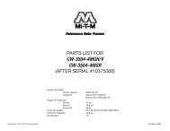
PARTS LIST FOR<br />
JP-1002/1502-0ME1<br />
Motor Horsepower:<br />
jp-1002-0me1:<br />
jP-1502-0ME1:<br />
Pump Oil Grade:<br />
Pump Oil Capacity:<br />
Nozzle Size:<br />
jP-1002-0ME1:<br />
jP-1502-0ME1:<br />
1.5 H.P.<br />
2.0 H.P.<br />
Mi-T-M Pump Oil #AW-4085-0016<br />
11.2 oz.<br />
1.40 mm<br />
1.25 mm<br />
©Copyright 2003, Mi-T-M Corporation®<br />
<br />
EX-9400-061708
This Parts Listing has been <strong>com</strong>piled for your benefit. You can be assured your Mi-T-M Cold Water Pressure Washer was constructed and designed with quality<br />
and performance in mind using over 25 years experience in the <strong>pressure</strong> <strong>washer</strong> business. Each <strong>com</strong>ponent has been rigorously tested to insure the highest level<br />
of acceptance.<br />
The contents of this Parts Listing are based on the latest product information available at the time of publication. Mi-T-M reserves the right to make changes in<br />
price, color, materials, equipment, specifications or models at any time without notice.<br />
WARNING<br />
THIS IS A PROFESSIONAL HIGH PRESSURE, COLD WATER PRESSURE WASHER. CAUTION SHOULD BE OBSERVED WHEN USING<br />
OR REPAIRING THIS UNIT! READ AND FOLLOW THE SAFETY WARNINGS LISTED BELOW BEFORE ATTEMPTING ANY REPAIRS ON<br />
THIS PRESSURE WASHER!<br />
SAFETY WARNINGS<br />
1. NEVER alter or modify the equipment. Be sure any accessory items and system <strong>com</strong>ponents being used will withstand the <strong>pressure</strong> developed. Use<br />
only genuine Mi-T-M <strong>parts</strong> for repair of your <strong>pressure</strong> <strong>washer</strong>. Failure to do so can cause hazardous operating conditions and will VOID warranty.<br />
2. NEVER make adjustments on machinery while the unit is connected to the engine without first removing the ignition cable from the spark plug.<br />
Turning over the machinery by hand during adjustment or cleaning might start the engine and machinery with it, causing serious injury to the operator.<br />
3. Know how to stop and bleed <strong>pressure</strong>s quickly. Be thoroughly familiar with controls.<br />
4. Before servicing the unit, turn unit off, relieve the water <strong>pressure</strong> and allow the unit to cool down. Do not make repairs while the unit is running.<br />
Service in a clean, dry, flat area. Block the wheels to prevent the unit from moving. Be especially careful to properly dispose of any flammable materials.<br />
5. After testing the machine, DO NOT leave the pressurized unit unattended. Shut off the unit and release trapped <strong>pressure</strong> before leaving.<br />
Table of Contents<br />
SPECIFICATIONS....................................................................................................................................................................................... 3<br />
frame assemblY FOR JP-1002/1502-0ME1......................................................................................................................................... 4<br />
motor assembly (851-0247 & 851-0248) ............................................................................................................................................ 6<br />
pump assembly (3-0071)........................................................................................................................................................................ 8<br />
UNLOADER (8-0493) & DETERGENT INJECTOR (46-0752) ASSEMBLY ............................................................................................ 10<br />
LANCE assembly (16-0412 and 16-0413)........................................................................................................................................... 12<br />
WIRING SCHEMATIC................................................................................................................................................................................ 14<br />
WIRING DIAGRAM.................................................................................................................................................................................... 15<br />
©Copyright 2003, Mi-T-M Corporation®<br />
<br />
EX-9400-061708
SPECIFICATIONS<br />
mODEl NumbER JP-1002-0mE1 JP-1502-0mE1<br />
Operating Pressure (PSI/bar): 1000/68.9 1500/103.4<br />
High Pressure Nozzle: 1.40 mm 1.25 mm<br />
Water Volume (GPm/lpm): 2.0/7.6<br />
motor:<br />
Totally enclosed fan cooled, circuit breaker thermal overload protection,<br />
35ft. power supply cord with Ground Fault Circuit Interrupter (GFCI)<br />
Horsepower 1.5 2.0<br />
Voltage<br />
Phase<br />
20<br />
Single<br />
Amps 15.0 20.0<br />
Pump:<br />
Oil Type<br />
Direct Driven, Oil Bath, Triplex Piston<br />
Mi-T-M Pump Oil #AW-4085-0016<br />
Oil Capacity (oz./liters) 11.2/0.3<br />
Plungers<br />
Manifold<br />
Valves<br />
Unloader<br />
Thermal Relief Valve<br />
Detergent Injector<br />
Ceramic<br />
Forged Brass<br />
Stainless Steel<br />
Adjustable<br />
Relieves heated water during unloader bypass stage<br />
Adjustable low <strong>pressure</strong> down stream from pump<br />
unit Net Weight (lbs/Kg) 90/4 92/42<br />
unit Shipping Weight (lbs/Kg) 7/53 9/54<br />
unit Net Dimension (in/cm)<br />
unit Shipping Dimension (in/cm)<br />
30Lx21Wx26H/76Lx53Wx66H<br />
30.5Lx21.5Wx26.5H/77.5Lx54.5Wx67.5H<br />
©Copyright 2003, Mi-T-M Corporation®<br />
<br />
EX-9400-061708
frame assemblY FOR JP-1002/1502-0ME1<br />
JP-1002/1502-0ME1-033108-JJT<br />
©Copyright 2003, Mi-T-M Corporation®<br />
<br />
EX-9400-061708
JP-002_502-0ME-03308-JJT<br />
FRAmE ASSEmblY FOR JP-1002_1502-0mE1<br />
REF. # DESCRIPTION PART # QTY. REF. # DESCRIPTION PART # QTY.<br />
Hubcap 33-008 2 24 White Die Cut (1000 PSI) 34-459 <br />
2 Wheel 4-007 2 - White Die Cut (1500 PSI) 34-0869 <br />
3 Washer 28-0008 4 25 Detergent Strainer 9-0050 <br />
4 Axle Spacer 62-076 2 26 Detergent Hose *(Four Feet Required) 5-002 <br />
5 Frame 5-0253A0 27 Unloader 8-0493 <br />
6 Quick Connect Socket 7-0004 28 Tag- Important Oil Plug 34-067 <br />
7 O-ring (Replacement Only) 25-023 29 Decal- Important Pump Instructions (See 34-9015) N/A Sep. <br />
8 Pump 3-007 30 Bolt 27-07 4<br />
9 Thermal Relief Valve 22-04 3 Washer 29-055 4<br />
0 Pop-Off Valve 22-0046 32 Key 43-0072 <br />
Elbow 23-004 33 Decal- Data Plate N/A <br />
2 Bolt 27-0067 8 34 Decal- Warning: Risk of Injection/Explosion (See 34-9015) N/A Sep. <br />
3 Washer 28-0022 8 35 Decal- Warning: Risk of Electrocution (See 34-9015) N/A Sep. <br />
4 Locknut 30-057 0 36 Decal- On/Off (See 34-9015) N/A Sep. <br />
5 Decal- Caution/Important (See 34-9015) N/A Sep. 37 Motor Assembly 1.5HP (GC-1002-0ME1) 85-0247 <br />
6 Hang Tag- Warning: Risk of Electrocution 34-035 - Motor Assembly 2.0HP (GC-1502-0ME1) 85-0248 <br />
7 Cable Tie 33-0022 38 High Pressure Hose 5-038 <br />
8 Bolt 27-0068 2 39 Quick Connect Plug 7-0006 <br />
9 Isolator 4-0008 2 40 Gun w/ Lance 6-0445 <br />
20 Inlet Filter 9-000 4 Variable Nozzle Assembly 1.40mm 6-043 <br />
2 garden Hose Fitting 23-0096 - Variable Nozzle Assembly 1.25mm 6-042 <br />
22 Front Handle Assy 7-094A0 42 Decal Kit (Inc. 15, 29, 34-36) 34-905<br />
23 Decal- Job Pro Placard (AC-1000) 34-0778 *Must Order in One Foot lengths<br />
©Copyright 2003, Mi-T-M Corporation®<br />
<br />
EX-9400-061708
motor assembly (851-0247 & 851-0248)<br />
851-0247-070301-EDW<br />
©Copyright 2003, Mi-T-M Corporation®<br />
<br />
EX-9400-061708
85-0247_85-0248-08303-Dlg<br />
mOTOR ASSEmblY (851-0248)<br />
REF. # DESCRIPTION PART # QTY.<br />
Hex Screw 27-8389 8<br />
2 Motor Box 52-004 <br />
3 O-ring 25-0338 <br />
4 Terminal 32-0099 2<br />
5 Switch (20 Amp) 32-0348 <br />
6 Crimp Splice 32-0359 <br />
7 Starting Capacitor 32-042 <br />
8 Running Capacitor 32-043 <br />
9 Lock<strong>washer</strong> 28-009 <br />
0 Strain Relief 32-0407 <br />
gFCI Cord 32-025 <br />
2 Motor Box Strap 52-0042 <br />
3 Motor- 2.0 H.P. (See 851-0248) N/A Sep. <br />
Complete Motor Assembly (Inc. 1-13) 85-0248<br />
©Copyright 2003, Mi-T-M Corporation®<br />
<br />
EX-9400-061708
pump assembly (3-0071)<br />
3-0071-060104-KZ<br />
©Copyright 2003, Mi-T-M Corporation®<br />
<br />
EX-9400-061708
3-0071-060104-KZ<br />
PumP ASSEmblY (3-0071)<br />
REF. # DESCRIPTION PART # QTY. REF. # DESCRIPTION PART # QTY.<br />
Crankcase 46-022 27 Washer 46-066 3<br />
2 Plug 39-008 2 28 Plunger- Ceramic 46-048 3<br />
3 O-ring 25-0052 29 O-ring 25-0045 3<br />
4 Drip Pan 46-0229 30 Back-up Ring 25-043 3<br />
5 Oil Seal 26-0 3 3 Washer 46-067 3<br />
6 Plug 39-007 32 Conecting Rod 43-0044 3<br />
7 Manifold- Brass 46-063 33 Crankcase Cover 46-05 <br />
8 Lock<strong>washer</strong> 29-053 2 34 Bolt 27-8409 4<br />
9 Bolt 27-8406 8 35 Cover O-ring 25-0332 <br />
0 O-ring (See 70-0009) N/A Sep. 6 36 Connecting Rod 46-052 3<br />
Valve Seat (See 70-0009) N/A Sep. 6 37 Piston guide 46-049 3<br />
2 Valve Plate (See 70-0009) N/A Sep. 6 38 Bolt 27-07 4<br />
3 Valve Spring (See 70-0009) N/A Sep. 6 39 Lock<strong>washer</strong> 29-055 4<br />
4 Valve Cage (See 70-0009) N/A Sep. 6 40 Flange 38-0032 <br />
5 O-ring 25-002 6 4 Lock<strong>washer</strong> 29-053 4<br />
6 Valve Plug 39-0035 6 42 Bolt 27-8409 4<br />
7 Valve Assembly (Includes 10-14) (See 70-0009) N/A Sep. 6 43 Bearing Spacer 46-0087 <br />
8 Head Ring (See 70-0024) N/A Sep. 3 44 O-ring 25-0060 <br />
9 V-packing (See 70-0024) N/A Sep. 3 45 Oil Seal 26-026 <br />
20 V-packing Retainer 46-058 3 46 Snap Ring 46-0245 <br />
2 O-ring 25-04 3 47 Ball Bearing 48-0024 <br />
22 O-ring 25-028 3 48 Crankshaft 46-0277 <br />
23 Oil level Indicator 46-04 Valve Kit (Includes 3 each 10-14, 17) 70-0009<br />
24 Bearing 48-009 V-packing Kit (Includes 3 each 18-19, 21-22) 70-0024<br />
25 Oil Dip Stick 46-043 V-packing Assembly (Includes 18-22) 70-0023<br />
26 Nut 46-068 3<br />
©Copyright 2003, Mi-T-M Corporation®<br />
<br />
EX-9400-061708
UNLOADER (8-0493) & DETERGENT INJECTOR (46-0752) ASSEMBLY<br />
8-0493-121000-RD<br />
©Copyright 2003, Mi-T-M Corporation®<br />
10<br />
EX-9400-061708
8-0493-02600--RD<br />
uNlOADER (8-0493) & DETERGENT INJECTOR (46-0752) ASSEmblY<br />
REF. # DESCRIPTION PART # QTY. REF. # DESCRIPTION PART # QTY.<br />
Adjusting Cap 39-0092 2 O-ring 25-0376 <br />
2 Spring 49-020 22 Connector 23-0285 <br />
3 Spring Retainer 8-042 23 Bypass Fitting N/A <br />
4 Piston Stem 46-0324 24 O-ring 25-0375 <br />
5 Back-up Ring 25-0206 25 Flow Balancer 8-0426 <br />
6 O-ring (See 70-0168) N/A Sep. 26 Spring 49-02 <br />
7 Set Screw 8-0479 27 Detergent Injector- 1.80mm 46-0752 <br />
8 Locknut 46-065 28 Orifice- 1.80mm 50-046 <br />
9 Piston Retainer 8-0424 29 Injector Body N/A <br />
0 O-ring (See 70-0168) N/A Sep. 3 30 Spring (See 852-0056) N/A Sep. <br />
O-ring (See 70-0168) N/A Sep. 3 Ball (See 852-0056) N/A Sep. <br />
2 Back-up Ring 25-0203 32 O-ring (See 852-0056) N/A Sep. <br />
3 Washer 8-0433 33 Piston Retainer N/A <br />
4 Washer 8-0427 3 34 Spring 49-0056 <br />
5 Connector 23-0286 35 O-ring (See 852-0056) N/A Sep. <br />
6 Body N/A 36 Barb 50-057 <br />
7 Valve and Ball Assembly 46-0320 37 Adjustable Knob 50-058 <br />
8 Bypass Seat 8-0430 Unloader Repair Kit (Inc. 4-6, 10-12, 17-19, 21) 70-068<br />
9 O-ring 25-0202 Injector Repair Kit (Inc. 30-32, 35) 852-0056<br />
20 Bypass Fitting N/A <br />
©Copyright 2003, Mi-T-M Corporation®<br />
11<br />
EX-9400-061708
16-0381-081103-dlg<br />
LANCE assembly (16-0412 and 16-0413)<br />
©Copyright 2003, Mi-T-M Corporation®<br />
12<br />
EX-9400-061708
6-038_6-042_43-0803-Dlg<br />
lANCE ASSEmblY (16-0412 AND 16-0413)<br />
REF. # DESCRIPTION PART # QTY. REF. # DESCRIPTION PART # QTY.<br />
Nozzle Assembly (Inc. 2-15) 8-0274 Plastic Housing (See 18-0274) N/A Sep. <br />
2 Nozzle Body 8-0284 2 O-ring 25-0342 <br />
3 Back-up Ring 25-0346 3 Angle Plate 8-0283 <br />
4 O-ring 25-0345 4 Nozzle Protector 8-0353 <br />
5 O-ring 25-0343 5 I.D. Pin- 1.25mm 8-0287 <br />
6 Back-up Ring 25-0344 - I.D. Pin- 1.40mm 8-0290 <br />
7 Nozzle- 1.25mm 6-07 6 Coupling 6-0378 <br />
- Nozzle- 1.40mm 6-073 7 Pipe 6-0379 <br />
8 Sleeve (See 18-0274) N/A Sep. Repair Kit (Inc. 4-6, 13) 70-0303<br />
9 O-ring 25-049 Complete Lance Assembly - 1.25mm (Inc. 1-17) 6-042<br />
0 Pin 43-0083 Complete Lance Assembly - 1.40mm (Inc. 1-17) 6-043<br />
©Copyright 2003, Mi-T-M Corporation®<br />
13<br />
EX-9400-061708
OMCWU189S-032395-DCE<br />
WIRING SCHEMATIC<br />
©Copyright 2003, Mi-T-M Corporation®<br />
14<br />
EX-9400-061708
OMCWU189D-032395-DCE<br />
WIRING DIAGRAM<br />
©Copyright 2003, Mi-T-M Corporation®<br />
15<br />
EX-9400-061708
Manufactured by Mi-T-M<br />
8650 Enterprise Drive, Peosta IA 52068<br />
563-556-7484/ Fax 563-556-1235<br />
©Copyright 2003, Mi-T-M Corporation®<br />
16<br />
EX-9400-061708