CO2 Engineâ¢- ICB - Driesen + Kern GmbH
CO2 Engineâ¢- ICB - Driesen + Kern GmbH
CO2 Engineâ¢- ICB - Driesen + Kern GmbH

You also want an ePaper? Increase the reach of your titles
YUMPU automatically turns print PDFs into web optimized ePapers that Google loves.
<strong>Driesen</strong> + <strong>Kern</strong> <strong>GmbH</strong><br />
CO 2 Engine - <strong>ICB</strong><br />
Sensor module for bio applications<br />
PRELIMINARY<br />
General<br />
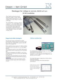
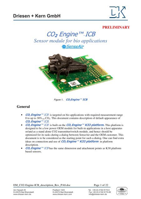
Figure 1. CO 2 Engine <strong>ICB</strong><br />
• CO 2 Engine <strong>ICB</strong> is targeted on bio applications with required measurement range<br />
0toupto30% vol CO 2 . This document contains description of default appearance of<br />
CO 2 Engine <strong>ICB</strong>.<br />
• CO 2 Engine <strong>ICB</strong> is built on the CO 2 Engine K33 platform. This platform is<br />
designed to be a low power OEM module for built-in applications in a host apparatus<br />
or/and as a stand alone <strong>CO2</strong> transmitter/switch module, and hence should be<br />
optimized for its tasks during a dialog between SenseAir and the OEM customer. This<br />
document is to be considered as the starting point for such a dialog. One can find extra<br />
ideas on connection and use of CO 2 Engine K33 platform in platform<br />
description.<br />
• CO 2 Engine <strong>ICB</strong> has the same dimension and attachment points as K30 platform<br />
based sensors.<br />
EM_<strong>CO2</strong>-Engine-<strong>ICB</strong>_description_Rev_PA8.doc Page 1 of 22<br />
Am Hasselt 25 Postfach 1424 Tel. +49 (0) 4192 8170-0<br />
D-24576 Bad Bramstedt D-24572 Bad Bramstedt Fax +49 (0) 4192 8170-99<br />
www.driesen-kern.de<br />
www.driesen-kern.com<br />
info@driesen-kern.de
PRELIMINARY<br />
Connection to host system alternatives<br />
(See electrical specifications in the table “Terminal description” below)<br />
Connection alternative A.<br />
CO 2 Engine <strong>ICB</strong> is built in into the customer’s system by connection via JP5. I 2 C<br />
communication is used to read measured data from the sensor. Detailed description of I 2 C<br />
communication with useful examples and troubleshooting can be found in “I2C comm guide<br />
2_10.pdf”<br />
Analogue GND<br />
I2C_SDA<br />
I2C_SCL<br />
G+<br />
G0<br />
DVCC = 3.3V<br />
Digital GND<br />
Figure 2. CO 2 Engine <strong>ICB</strong> Possible connection terminals for reading via I 2 C.<br />
Note: Both Digital GND and Analog GND are connected to G0 internally.<br />
EM_<strong>CO2</strong>-Engine-<strong>ICB</strong>_description_Rev_PA8.doc Page 2 of 22
PRELIMINARY<br />
Connection alternative B.<br />
CO 2 Engine <strong>ICB</strong> is built in into the customer’s system by connection via JP1 or some<br />
part of it. UART with Modbus protocol communication is used to read measured data from the<br />
sensor. CO 2 Engine <strong>ICB</strong> shares specification and Modbus register map with <strong>CO2</strong> Engine K30<br />
sensor family. Specification can be found in “ModBus on <strong>CO2</strong> Engine K30 rev1_07.pdf” and<br />
“K30 ModBus map rev1_01.xls”<br />
View from component side:<br />
Din3<br />
UART_TxD<br />
UART_RxD<br />
DVCC = 3.3V<br />
G0<br />
G+<br />
G0<br />
Din2<br />
G0<br />
Din0<br />
Din1<br />
G0<br />
Figure 3a. CO 2 Engine <strong>ICB</strong> Possible connection terminals for reading via UART.<br />
View from OBA side:<br />
Note: LEDs are optional and are not planned to operate in default appearance.<br />
Through mounted LEDs options are available as well.<br />
G0<br />
Din2<br />
G0<br />
Din0<br />
Din1<br />
G0<br />
Din3<br />
UART_TxD<br />
UART_RxD<br />
DVCC = 3.3V<br />
G0<br />
G+<br />
Figure 3b. CO 2 Engine <strong>ICB</strong> Possible connection terminals for reading via UART.<br />
EM_<strong>CO2</strong>-Engine-<strong>ICB</strong>_description_Rev_PA8.doc Page 3 of 22
PRELIMINARY<br />
Connection alternative C.<br />
CO 2 Engine <strong>ICB</strong> is built in into the customer’s system by connection via terminals.<br />
Signal lines on these terminals are protected and long wires may be used for connection to the host<br />
system.<br />
5.08 mm pitch:<br />
2mmpitch:<br />
Figure 4a. CO 2 Engine <strong>ICB</strong> Possible connection terminals for connection by long wires.<br />
OUT2 (Analogue output)<br />
OUT1 (Open collector)<br />
GN0<br />
G+<br />
OUT2 (Analogue output)<br />
OUT1 (Open collector)<br />
GN0<br />
G+<br />
Figure 4b. CO 2 Engine <strong>ICB</strong> Possible connection terminals for connection by long wires.<br />
Note:<br />
OUT1, open collector is configured to provide PWM signal,<br />
see specification below.<br />
EM_<strong>CO2</strong>-Engine-<strong>ICB</strong>_description_Rev_PA8.doc Page 4 of 22
PRELIMINARY<br />
Connection alternative D.<br />
Combination of alternatives B and C. It’s possible to use both UART and OUT1 at the<br />
same time. In the same way it’s possible to use alternatives A and C, I2C and OUT1 at the<br />
same time.<br />
G0<br />
Din2<br />
G0<br />
Din0<br />
Din1<br />
G0<br />
Din3<br />
UART_TxD<br />
UART_RxD<br />
DVCC = 3.3V<br />
G0<br />
G+<br />
OUT2 (Analogue output)<br />
OUT1 (Open collector)<br />
GN0<br />
G+<br />
Figure 5. CO 2 Engine <strong>ICB</strong> Possible connection terminals for connection by long wires and UART at<br />
the same time.<br />
EM_<strong>CO2</strong>-Engine-<strong>ICB</strong>_description_Rev_PA8.doc Page 5 of 22
PRELIMINARY<br />
Diffusion or tube IN/OUT alternatives<br />
CO 2 Engine <strong>ICB</strong> can be supplied in diffusion modification with or without O-ring.<br />
Figure 6. CO 2 Engine <strong>ICB</strong> diffusion model.<br />
CO 2 Engine <strong>ICB</strong> can be supplied in tube in/out modification with different orientation<br />
of tube attachment head in steps of 120 degrees.<br />
Figure 7. CO 2 Engine <strong>ICB</strong> tube IN/OUT model.<br />
EM_<strong>CO2</strong>-Engine-<strong>ICB</strong>_description_Rev_PA8.doc Page 6 of 22
PRELIMINARY<br />
test/sample<br />
gas output port<br />
test/sample<br />
gas input port<br />
Figure 8a . CO 2 Engine <strong>ICB</strong> Test/sample gas ports.<br />
Figure 8b . CO 2 Engine <strong>ICB</strong> Possible test/sample gas ports installations.<br />
EM_<strong>CO2</strong>-Engine-<strong>ICB</strong>_description_Rev_PA8.doc Page 7 of 22
Terminal description<br />
PRELIMINARY<br />
The table below specifies terminals and I/O options available in the general K33 platform<br />
(see also the alternative connection pictures above).<br />
Functional group<br />
Descriptions and ratings<br />
Power supply (all connection alternatives)<br />
G+<br />
referred to G0<br />
Power supply plus terminal<br />
Protected by series 3.3R resistor and zener diode<br />
Absolute maximum ratings 5 to 14V, stabilized to within 10%<br />
Can withstand reverse connection! (TBD)<br />
G0<br />
DVCC = 3.3V<br />
Communication<br />
UART<br />
(UART_TxD,<br />
UART_RxD)<br />
Power supply minus terminal<br />
Sensor’s reference (ground) terminal<br />
Output from sensor’s digital voltage regulator.<br />
Series resistance<br />
10 R<br />
Available current<br />
12mA<br />
Voltage tolerance (unloaded) +-3% max (+-0.75% typ)<br />
Output may be used to power circuit (microcontroller) in host system or to<br />
power logical level converter if master processor runs at 5V supply voltage.<br />
CMOS physical layer, ModBus communication protocol.<br />
(refer “ModBus on <strong>CO2</strong> Engine K30 rev1_07.pdf” or later version for<br />
details)<br />
UART_RxD line is configured as digital input.<br />
Input high level is 2.1V min<br />
Input low level is 0.8V max<br />
UART_TxD line is configured as digital output.<br />
Output high level is 2.3V (assuming 3.3V DVCC) min.<br />
Output low level is 0.75V max<br />
UART_RxD input is pulled up to DVCC = 3.3V by 56 kOhm<br />
UART_TxD output is pulled up to DVCC = 3.3V by 56 kOhm<br />
ABSOLUTE MAX RATING G0-0.5V ….. DVCC + 0.5V<br />
I2C extension.<br />
(I2C_SCL,<br />
I2C_SDA)<br />
Pull-up to DVCC = 3.3V.<br />
(refer “I2C comm guide rev2_00 DRAFT.pdf” or later version for details)<br />
ABSOLUTE MAX RATING G0-0.5V ….. DVCC + 0.5V<br />
Outputs<br />
OUT1, OC<br />
(Open collector)<br />
Digital output, Open collector<br />
Series resistance<br />
Max sink current<br />
120 R<br />
40mA<br />
May be configured as<br />
1. Alarm indication output<br />
2. PWM output, 10 (alt. 12 to 16) bit resolution. Period 1 .. 1000 msec<br />
3. Pulse length proportional to measured <strong>CO2</strong> value.<br />
EM_<strong>CO2</strong>-Engine-<strong>ICB</strong>_description_Rev_PA8.doc Page 8 of 22
PRELIMINARY<br />
OUT2<br />
Analog output 0..5V<br />
Buffered linear output 0..4 or 1..4VDC or 0..5V or 1..5V, depending on<br />
specified power supply and sensor configuration. R OUT<br />
< 100 Ω, R LOAD<br />
>5kΩ<br />
Load to ground only!<br />
Resolution 5mV<br />
RELAY<br />
(RelayPoleNC<br />
RelayPoleCom<br />
RelayPoleNO)<br />
RELAY<br />
It’s not a standard option.<br />
Maximum switching capability<br />
1A/50VAC/24VDC<br />
Digital I/Os, used as Inputs in standard configuration. May be implemented as jumper field<br />
Din0<br />
Din1<br />
Din2<br />
Digital switch inputs in standard configuration,<br />
Pull-up 56k to DVCC 3.3V. Driving it Low or connecting to G0<br />
activates input.<br />
Pull-up resistance is decreased to 4..10k during read of input or<br />
jumper. Advantages are lower consumption most of the time the<br />
input/jumper is kept low and larger current for jumpers read in order<br />
to provide cleaning of the contact.<br />
Din3<br />
Can be used for zero or background calibration forcing.<br />
Can be used to switch output range or to force output to predefined state.<br />
All depends on customer needs, see description of default appearance<br />
below..<br />
R/T control line for UART connection to RS485 driver.<br />
Table I. I/O notations used in this document for the K33 platform with some descriptions and ratings.<br />
Please, beware of the red colored texts that pinpoint important features for the system integration!<br />
EM_<strong>CO2</strong>-Engine-<strong>ICB</strong>_description_Rev_PA8.doc Page 9 of 22
Mechanical drawings<br />
PRELIMINARY<br />
Figure 9 . CO 2 Engine <strong>ICB</strong> mechanical drawing. Hole/contacts positions.<br />
EM_<strong>CO2</strong>-Engine-<strong>ICB</strong>_description_Rev_PA8.doc Page 10 of 22
PRELIMINARY<br />
Figure 10a . CO 2 Engine <strong>ICB</strong> OBA position. Tube IN/OUT model<br />
Figure 10b . CO 2 Engine <strong>ICB</strong> OBA position. Diffusion model..<br />
EM_<strong>CO2</strong>-Engine-<strong>ICB</strong>_description_Rev_PA8.doc Page 11 of 22
PRELIMINARY<br />
Figure 11 . <strong>CO2</strong>Engine <strong>ICB</strong> mechanical drawing. Tube IN/OUT model<br />
EM_<strong>CO2</strong>-Engine-<strong>ICB</strong>_description_Rev_PA8.doc Page 12 of 22
PRELIMINARY<br />
Figure 12 . <strong>CO2</strong>Engine <strong>ICB</strong> mechanical drawing. Diffusion model.<br />
EM_<strong>CO2</strong>-Engine-<strong>ICB</strong>_description_Rev_PA8.doc Page 13 of 22
PRELIMINARY<br />
Ground / Shield attachments<br />
Both Analog ground (AGND) and digital ground (DGND) are connected internally to the<br />
G0 terminal of the sensor. AGND is connected to the most sensitive analogue part of the<br />
sensor and DGND is connected to the digital part of the sensor.<br />
Do NOT connect AGND and DGND together externally to sensor!<br />
AGND<br />
Analogue ground<br />
DGND<br />
Digital ground<br />
Maintenance<br />
Figure 13 . CO 2 Engine <strong>ICB</strong> ground / shield attachment<br />
The CO 2 Engine <strong>ICB</strong> is basically maintenance free in normal environments thanks to the<br />
built-in self-correcting ABC algorithm. Discuss your application with SenseAir in order to<br />
get advice for a proper calibration strategy.<br />
When checking the sensor accuracy, PLEASE NOTE that the sensor accuracy is defined at<br />
continuous operation (at least 3 weeks after installation)!<br />
Calibration<br />
The default sensor OEM unit is maintenance free in normal environments thanks to the<br />
built-in self-correcting ABC algorithm (Automatic Baseline Correction). This algorithm<br />
constantly keeps track of the sensor’s lowest reading over a 7,5 days interval and slowly<br />
corrects for any long-term drift detected as compared to the expected fresh air value of<br />
0.04% vol CO 2 .<br />
ABC algorithm may be adapted for particular application.<br />
For example, sensor may be forced to sample data used for ABC only during first few<br />
hours after powering up when container is open and <strong>CO2</strong> concentration is about 400 ppm.<br />
EM_<strong>CO2</strong>-Engine-<strong>ICB</strong>_description_Rev_PA8.doc Page 14 of 22
PRELIMINARY<br />
Another possibility comes if end user is going to pump fresh air through the sensor<br />
some time. Then it can force calibration by shorting corresponding digital input.<br />
Rough handling and transportation might result in a reduction of sensor reading<br />
accuracy. With time, the ABC function will tune the readings back to the correct numbers.<br />
The default “tuning speed” is however limited. This limit is application specific. For post<br />
calibration convenience, in the event that one cannot wait for the ABC algorithm to cure any<br />
calibration offset, two switch inputs Din1 and Din2 are defined for the operator to select one<br />
out of two prepared calibration codes. If Din1 is shorted to ground, for a minimum time of 8<br />
seconds, the internal calibration code bCAL (background calibration) is executed, in which<br />
case it is assumed that the sensor is operating in a fresh air environment (400 ppm CO 2 ). If<br />
Din2 is shorted instead, for a minimum time of 8 seconds, the alternative operation code CAL<br />
(zero calibration) is executed in which case the sensor must be purged by some gas mixture<br />
free from CO 2 (i.e. Nitrogen or Soda Lime CO 2 scrubbed air). If unsuccessful, please wait at<br />
least 10 seconds before repeating the procedure again. Make sure that the sensor environment<br />
is steady and calm!<br />
Input<br />
Switch Terminal<br />
(normally open)<br />
Din1<br />
Default function<br />
(when closed for minimum 8 seconds)<br />
bCAL (background calibration) assuming 400 ppm CO 2 sensor exposure<br />
Din2<br />
CAL (zero calibration) assuming 0 ppm CO 2 sensor exposure<br />
Table II. Switch input default configurations for CO 2 Engine <strong>ICB</strong><br />
CAL<br />
G0<br />
Din2<br />
bCAL<br />
Din1<br />
G0<br />
Figure 14. CO 2 Engine <strong>ICB</strong> calibration jumpers.<br />
EM_<strong>CO2</strong>-Engine-<strong>ICB</strong>_description_Rev_PA8.doc Page 15 of 22
PRELIMINARY<br />
CO 2 Engine <strong>ICB</strong> - Technical specification (continuous operation)<br />
General Performance:<br />
Storage Temperature Range ................-40 to +70 °C, (no condensation, eventual validation of condensation acceptability<br />
has to be discussed with customer)<br />
Sensor Life Expectancy ........................> 15 years 2<br />
Maintenance Interval ............................Subject for discussion with customer. Maintenance-free if ABC (Auto Baseline<br />
Correction) algorithm is applicable. See discussion of ABC algorithm on page 14.<br />
Self-Diagnostics ...................................complete function check of the sensor module<br />
Warm-up Time ......................................≤ 1minif started at normal operating environment condition<br />
Conformance with the standards ...........Emission: EN61000-6-3:2007<br />
Immunity: EN61000-6-1:2007<br />
RoHS directive 2002/95/EG<br />
The following vibration and shock behaviour has to be tested after agreement with<br />
customer. Other models using the same techniques and components proved to comply with the following standards:<br />
Conformance with standards.......... Mechanical shock test IEC 60068-2-27 Test Ea<br />
.......... Random vibration test IEC 60068-2-64 Test Fh<br />
Vibration immunity Test severity .... IEC TR 60721-4-5 table 5: IEC 60721-3-5, Class 5M3 (3,6 gRMS)<br />
“Mechanical conditions in road vehicles in areas without well-developed road systems,<br />
light-weighted vehicles, tracked vehicles and self propelled machines, including<br />
installations in places which may be directly hit by flying stones”<br />
Random vibration Test severity ..... IED TR 60721-4-2 table 7: IEC 60721-3-2, Class 2M3 (3,2 gRMS)<br />
“Transportation in lorries, trailers and all other kinds of transportation in areas without<br />
well-developed road systems, by trains with shock reducing buffers and by ships”,<br />
....... IEC 60721-3-2, Class A (1,0 gRMS)<br />
“Instrumentation and automation equipment on ships”<br />
Operating Temperature Range ............-10 to 50 °C<br />
Operating Humidity Range ...................0 to 95% RH (non-condensing)<br />
Operating Environment .........................Residential, commercial, industrial spaces and Potentially dusty air ducts used in<br />
HVAC (Heating Ventilation and Air-Conditioning) systems. 4<br />
Electrical / Mechanical:<br />
Power Input ...........................................5-14 VDC max rating, stabilized to within 10% (on board protection circuits) 3<br />
Current Consumption ............................40 mA average<br />
< 150 mA peak current (averaged during IR lamp ON, 120 msec)<br />
< 250 mA peak power (during IR lamp start-up, the first 50 msec)<br />
Electrical Connections4<br />
........................Subject for discussion with customer, variants are suggested in this document<br />
Dimensions ........................................5,1 x 5,7 x 1,4 cm (Length x Width x approximate Height)<br />
CO 2 Measurement: 4<br />
Sensing Method ....................................non-dispersive infrared (NDIR) waveguide technology with ABC<br />
automatic background calibration algorithm<br />
Sampling Method ..................................diffusion or flow, Subject for discussion with customer<br />
Response Time (T 1/e<br />
) ............................TBD sec, faster for flow, longer for diffusion<br />
Measurement Range ............................0 to 30% vol.<br />
Digital resolution....................................0.001% vol<br />
Repeatability .........................................± 0,1 %vol. <strong>CO2</strong> ± 2 % of measured value (TBD, may be improved after tests)<br />
Accuracy 1, 5 ..........................................± 0,2 %vol. <strong>CO2</strong> ± 3 % of measured value<br />
Pressure Dependence...........................+ 1.6 % reading per kPa deviation from normal pressure, 100 kPa<br />
On-board calibration support .................Din1 switch input to trigger Background Calibration @ 400 ppm (0.04% vol) CO 2<br />
Din2 switch input to trigger Zero Calibration @ 0 ppm CO 2<br />
Linear Signal Output: 4,6<br />
OUT2<br />
D/A Resolution .........................5 mV<br />
Linear Conversion Range ........0 - 5 VDC for 0 – 30% vol.<br />
Electrical Characteristics...........R OUT<br />
< 100 Ω, R LOAD<br />
>5kΩ , Power input > 5,5 V<br />
Note 1: In normal IAQ applications. Accuracy is defined after minimum 3 weeks of continuous operation. However, some industrial<br />
applications do require maintenance. Please, contact SenseAir for further information!<br />
Note 2: SO 2 enriched environments are excluded.<br />
Note 3: Notice that absolute maximum rating is 14V, so that sensor can be used with 12V+-10% supply.<br />
Note 4: Different options exist and can be customized depending on the application. Please, find possible options in this document and<br />
contact SenseAir for further information!<br />
Note 5: Accuracy is specified over operating temperature range. Specification is referenced to certified calibration mixtures. Uncertainty of<br />
calibration gas mixtures (+-2% currently) is to be added to the specified accuracy for absolute measurements.<br />
Note 6: For the buffered outputs OUT1 and OUT2 the maximum output voltage range equals power voltage input minus 0,5 V<br />
6<br />
EM_<strong>CO2</strong>-Engine-<strong>ICB</strong>_description_Rev_PA8.doc Page 16 of 22
PRELIMINARY<br />
PWM Output:<br />
Electrical Characteristics ............... Open collector with series 120R resistor, 10kΩ pull-up resistor to protected power (+)<br />
Minimum output concentration ....... 0% vol<br />
Output cycle period ....................... 1004ms<br />
Output high level min duration ....... 2.0ms (@ 0% vol<br />
)<br />
Output high level max duration ...... 1002ms (@ 20% vol.<br />
)<br />
Resolution ............................. 0.5ms (@0.01% vol<br />
= 100 ppm)<br />
Sensor PWM output timing diagram<br />
0 % vol:<br />
2.0ms<br />
2.0ms<br />
1004ms<br />
0.01 %vol:<br />
2.5ms<br />
2.5ms<br />
1004ms<br />
0.02 %vol:<br />
3.0ms<br />
3.0ms<br />
1004ms<br />
19.98%vol<br />
1001ms<br />
3.0ms<br />
1004ms<br />
19.99%vol<br />
1001.5ms<br />
2.5ms<br />
1004ms<br />
20.00%vol<br />
1002ms<br />
2.0ms<br />
1004ms<br />
Figure 15. CO 2 Engine <strong>ICB</strong> OUT1 timing diagram.<br />
EM_<strong>CO2</strong>-Engine-<strong>ICB</strong>_description_Rev_PA8.doc Page 17 of 22
PRELIMINARY<br />
Materials<br />
Component / coating Material Notes<br />
PCB<br />
Surface finish of<br />
unsoldered copper on<br />
PCB<br />
Solder mask<br />
FR4,<br />
Base laminate – copper clad glass<br />
base epoxy resin in accordance<br />
with IPC-4101/124<br />
Gold plated, ENIG,<br />
thickness 0.05 um min<br />
Liquid photo-image able<br />
Conformal coating TBD Only component side is coated.<br />
OBA LCP700 TBD, it is plastic from LCP<br />
family. It’s chemically inert<br />
plastic stable in most chemicals.<br />
OBA coating OBA is not coated Absence of coating provides<br />
extra resistance of OBA against<br />
corrosive environments<br />
Gases that may affect sensor’s operation<br />
Since optical part has no reflective coating, stability of the sensor is governed by corrosion<br />
resistance of electronic assembly.<br />
Corrosive environments containing but not limited by hydrogen sulfide, ammonia, ozone,<br />
sulphuric acid, sulfur dioxide should be avoided.<br />
EM_<strong>CO2</strong>-Engine-<strong>ICB</strong>_description_Rev_PA8.doc Page 18 of 22
Use ideas (connections)<br />
Alternative E.<br />
PRELIMINARY<br />
CO 2 Engine <strong>ICB</strong> is a stand-alone module connected to the host system by 3-wire<br />
interface (JP13 may be chosen to be 3 pole connector) with power supply and open collector<br />
output for alarm condition indication. Open collector output may drive LED or relay or buzzer in<br />
the case of alarm conditions.<br />
Open collector may provide PWM signal with duty cycle representing <strong>CO2</strong> concentration<br />
Not Used<br />
OUT1, OC<br />
G0<br />
G+<br />
EM_<strong>CO2</strong>-Engine-<strong>ICB</strong>_description_Rev_PA8.doc Page 19 of 22
PRELIMINARY<br />
Alternative F.<br />
CO 2 Engine <strong>ICB</strong> is a stand-alone module connected to the host system by 3-wire<br />
interface (JP8 may be chosen to be 3 pole terminal) with power supply and open collector output<br />
for alarm condition indication. Open collector output may drive LED or relay or buzzer in the case<br />
of alarm conditions.<br />
Open collector may provide PWM signal with duty cycle representing <strong>CO2</strong> concentration<br />
Alternative E.<br />
CO 2 Engine <strong>ICB</strong> is a stand-alone module with open collector output and NC/NO relay<br />
Open collector may provide PWM signal with duty cycle representing <strong>CO2</strong> concentration<br />
RelayPoleNC<br />
RelayPoleCom<br />
RelayPoleNO<br />
OUT1 Open Collector<br />
G0<br />
G+<br />
OUT2 (Analogue output)<br />
OUT1 (Open collector)<br />
GN0<br />
G+<br />
EM_<strong>CO2</strong>-Engine-<strong>ICB</strong>_description_Rev_PA8.doc Page 20 of 22
<strong>Driesen</strong> + <strong>Kern</strong> <strong>GmbH</strong><br />
PRELIMINARY<br />
WARRANTY and Limitation of Liability<br />
1. SenseAir warrants that for a period of twenty four (24) months following receipt by Buyer<br />
the Product supplied by SenseAir to Buyer will be, under normal use and care, free from<br />
defects in workmanship or material and to be in material conformity with SenseAir's<br />
specifications. Units returned to SenseAir for warranty repairs shall be shipped to SenseAir, at<br />
Buyer’s expense, according to SenseAir's instruction. Within ninety (90) days of the receipt of<br />
product, SenseAir shall replace or repair such units and shall ship them to Buyer’s designated<br />
return destination freight pre paid.<br />
2. Warranty Limitations. This warranty does not extend to any unit that has been<br />
subject to misuse, neglect or accident; that has been damaged by causes external to the<br />
unit; that has been used in violation of SenseAir's instructions; that has been affixed to any<br />
non-standard Accessory attachment; or that has been modified, disassembled, or reassembled<br />
by anyone other than SenseAir.<br />
3. The retailer is not responsible for any consequential loss or damages, which may occur by<br />
reason of purchase and use of this product. The warranty is, in any event, strictly limited to<br />
the replacement/repair of the product<br />
EM_<strong>CO2</strong>-Engine-<strong>ICB</strong>_description_Rev_PA8.doc Page 21 of 22<br />
Am Hasselt 25 Postfach 1424 Tel. +49 (0) 4192 8170-0<br />
D-24576 Bad Bramstedt D-24572 Bad Bramstedt Fax +49 (0) 4192 8170-99<br />
www.driesen-kern.de<br />
www.driesen-kern.com<br />
info@driesen-kern.de
PRELIMINARY<br />
Revision history<br />
Edition Date By Description<br />
PA1 2008-05-01 PZ First appearance<br />
PA2 2008-07-21 IU Correcting pictures<br />
PA3 2008-07-27 IU Correcting pictures<br />
PA4 2008-08-07 PZ Update with new pictures and PWM output.<br />
PA5 2008-08-08 PZ Added materials chapter.<br />
PA6 2008-08-08 PZ Convert CNT spec into <strong>ICB</strong> spec with corrections by<br />
HM<br />
PA8 2009-11-02 JA Correcting pictures<br />
EM_<strong>CO2</strong>-Engine-<strong>ICB</strong>_description_Rev_PA8.doc Page 22 of 22