SenseAir ® S8 - Driesen + Kern GmbH
SenseAir ® S8 - Driesen + Kern GmbH
SenseAir ® S8 - Driesen + Kern GmbH

You also want an ePaper? Increase the reach of your titles
YUMPU automatically turns print PDFs into web optimized ePapers that Google loves.
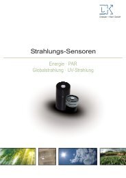
Gas and Air Sensors<br />
<strong>Driesen</strong> + <strong>Kern</strong> <strong>GmbH</strong><br />
Product Specification<br />
<strong>SenseAir</strong> ® <strong>S8</strong><br />
Miniature CO2 sensor<br />
Document<br />
PSP 108<br />
Rev<br />
8<br />
Page<br />
1 (10)<br />
<strong>Driesen</strong>+<strong>Kern</strong> <strong>GmbH</strong><br />
Am Hasselt 25<br />
D-24576 Bad Bramstedt<br />
Tel. +49 (0) 4192 8170-0<br />
www.driesen-kern.de Fax +49 (0) 4192 8170-99<br />
www.driesen-kern.com<br />
info@driesen-kern.de
Preliminary<br />
<strong>SenseAir</strong> ® <strong>S8</strong><br />
Miniature infrared CO 2 sensor module<br />
Warning! ESD<br />
sensitive device!<br />
Figure 1. <strong>SenseAir</strong> ® <strong>S8</strong> Article no. 004-0-0050<br />
Key technical specification<br />
Item<br />
<strong>SenseAir</strong> ® <strong>S8</strong><br />
Target gas CO 2<br />
Operating Principle<br />
Measurement range<br />
Non-dispersive infrared (NDIR)<br />
0.04 to 2% volume CO2 (Note 1)<br />
0 to 3.2% volume CO2 extended range (Note 2)<br />
Accuracy ±0.02% volume CO2 ±3% of reading (Notes 3 and 4)<br />
Response time 2 minutes by 90%<br />
Operating temperature<br />
Operating humidity<br />
Storage temperature<br />
Dimensions<br />
Weight<br />
Power supply<br />
Power consumption<br />
Life expectancy<br />
Compliance with<br />
Serial communication<br />
Alarm output, Open Collector<br />
PWM output, 1 kHz<br />
Maintenance<br />
0 to 50° C<br />
0 to 85% RH non condensed (note5)<br />
-40 to +70 C<br />
32.7 x 19.7 x 9.9 mm<br />
< 8 grams<br />
4.5 V to 5.25 V unprotected against surges and reverse connection<br />
300 mA peak, 30 mA average<br />
15+ years in normal commercial environments<br />
Emission: EN 61000-6-3:2007, EN 61000-6-4:2007<br />
Immunity: EN 61000-6-1:2007<br />
RoHS directive 2002/95/EG<br />
UART, Modbus protocol (Note 6). Direction control pin for direct<br />
connection to RS485 receiver integrated circuit.<br />
Alarm state open<br />
0 to 100% duty cycle for 0 to 20000 ppm<br />
3.3V push-pull CMOS output, unprotected<br />
8500/6500 ppm normally conducting<br />
max 100 mA. Transistor open at CO 2<br />
High, OR Power Low, OR at Sensor<br />
Failure<br />
Maintenance-free for normal indoor applications with <strong>SenseAir</strong> ® ABC on.<br />
Table 1. Key technical specification for the <strong>SenseAir</strong> ® <strong>S8</strong><br />
__________________________________________________________________________________________<br />
Note 1: Sensor is designed to measure in the range 0 to 20000 ppm with specified in the table accuracy. Nevertheless<br />
exposure to concentrations below 400 ppm may result in incorrect operation of ABC algorithm and shall be<br />
avoided for model with ABC on.<br />
Note 2: Sensor provides readings via UART in the extended range but the accuracy is degraded compared to specified<br />
in the table one.<br />
Note 3: Sensor requires to be exposed to fresh air at least every four weeks. Accuracy is defined after minimum 5<br />
weeks of continuous operation. However, some industrial applications do require maintenance. Please, contact<br />
<strong>SenseAir</strong> for further information!<br />
Note 4: Accuracy is specified over operating temperature range. Specification is referenced to certified calibration<br />
mixtures. Uncertainty of calibration gas mixtures (+-2% currently) is to be added to the specified accuracy for<br />
absolute measurements.<br />
Note 5: Specification provides operating conditions 100% tested in production.<br />
Note 6: See specification { Modbus on <strong>SenseAir</strong>_R_ <strong>S8</strong> rev_P11_1_00.doc preliminary specification}<br />
CO 2<br />
Document<br />
PSP 107<br />
Rev<br />
8<br />
Page<br />
2 (10)
Preliminary<br />
Absolute maximum ratings<br />
Stress greater than those listed in Table 2 may cause permanent damage to the device. These ratings<br />
are stress ratings only. Operation of the device at any condition outside those indicated in the<br />
operational section of these specifications is not implied. Exposure to absolute maximum rating for<br />
extended periods may affect device reliability.<br />
Parameter Minimum Maximum Units Notes<br />
Ambient temperature under bias - 40 85 C<br />
Voltage on G+ pin with respect to G0 pin - 0.3 5.5 V 1, 2<br />
Maximum output current from active output pin - 25 + 25 mA 1<br />
Maximum current on input - 5 + 5 uA 1<br />
Maximum voltage on UART lines, PWM and bCAL_in - 0.3 DVCC_out + 0.5 V 1<br />
Maximum voltage on Alarm_OC - 0.3 12 V 1,3<br />
Table 2. Absolute maximum ratings specification for the <strong>SenseAir</strong> ® <strong>S8</strong><br />
__________________________________________________________________________________________<br />
Note 1: Specified parameter relies on specification of subcontractor and is not tested by <strong>SenseAir</strong><br />
Note 2: Refer chapter “Terminal Description” for rated voltage information<br />
Note 3: Alarm_OC pin is internally pulled up to G+. External pull up to higher voltage will provide resistive divider powering<br />
sensor via high resistance.<br />
Sample gas diffusion area<br />
Diffusion area<br />
Figure 2. Diffusion area<br />
Pin assignment<br />
G+<br />
G0<br />
Alarm_OC<br />
PWM 1kHz<br />
DVCC_out<br />
UART_RxD<br />
UART_TxD<br />
UART_R/T<br />
bCAL_in/CAL<br />
Figure 3. Attachment to customer’s PCB, not in scale.<br />
Document<br />
PSP 107<br />
Rev<br />
8<br />
Page<br />
3 (10)
Preliminary<br />
Terminals description<br />
The table below specifies terminals and I/O options dedicated in <strong>SenseAir</strong> ® <strong>S8</strong> model.<br />
Pin Function Pin description /<br />
Parameter description<br />
Power pins<br />
G0<br />
G+ referred to<br />
G0<br />
DVCC_out<br />
Communication pins<br />
UART_TxD<br />
UART_RxD<br />
UART_R/T<br />
Power supply minus terminal<br />
Sensor’s reference (ground) terminal<br />
Power supply plus terminal<br />
Operating voltage range<br />
Output<br />
from sensor’s voltage regulator<br />
Output may be used to logical level<br />
converter if master processor runs at 5V<br />
supply voltage.<br />
Series resistance<br />
Nominal voltage<br />
Allowed source current<br />
Voltage precision (Note 1)<br />
UART data transmission line<br />
Configured as digital output<br />
Electrical specification<br />
Unprotected against reverse<br />
connection!<br />
4.5 V to 5.25 V<br />
Induced noise or excessive current<br />
drawn may affect sensor<br />
performance. External series<br />
resistor is strongly recommended if<br />
this pin is used<br />
No internal protection!<br />
3.3 VDC<br />
6 mA max<br />
± 0.75% is typical, ± 3% is max<br />
No internal protection<br />
Pulled up to DVCC_out at<br />
processor reset<br />
(power up and power down)<br />
Absolute max voltage range (Note 1) G0 - 0.3V to DVCC_out + 0.5V<br />
Internal pull up to DVCC_out resistor<br />
Output low level (Note 1)<br />
Output high level (Note 1)<br />
UART data receive line<br />
Configured as digital input<br />
120k<br />
0.75 VDC max at 10mA sink<br />
2.4 VDC at 2mA source<br />
No internal protection<br />
Pulled up to DVCC_out at<br />
processor reset<br />
(power up and power down)<br />
Absolute max voltage range(Note 1) G0 - 0.3V to DVCC_out + 0.5V<br />
Internal pull up to DVCC_out resistor<br />
120k<br />
Input low level (Note 1) - 0.3V to 0.75V<br />
Input high level (Note 1) 2.3V to DVCC_out + 0.3V<br />
Direction control line for half duplex<br />
RS485 transceiver like MAX485.<br />
Configured as digital output<br />
No internal protection,<br />
Pulled down at processor reset<br />
(power up and power down)<br />
Absolute max voltage range(Note 1) G0 - 0.3V to DVCC_out + 0.5V<br />
Internal pull down to G0 resistor<br />
Output low level (Note 1)<br />
Output high level (Note 1)<br />
120k<br />
0.75 VDC max at 10mA sink<br />
2.4 VDC at 2mA source<br />
Table 3. I/O notations, description and electrical specification. Please, continue on the next page!<br />
Document<br />
PSP 107<br />
Rev<br />
8<br />
Page<br />
4 (10)
Preliminary<br />
Pin Function<br />
Input / output<br />
bCAL_in/ CAL<br />
Pin description /<br />
Parameter description<br />
Digital input forcing background<br />
calibration. Configured as digital input<br />
(when closed for minimum 4, max 8<br />
seconds) bCAL (background<br />
calibration) assuming 400 ppm CO2<br />
sensor exposure<br />
Electrical specification<br />
No internal protection,<br />
Pulled up to DVCC_out at<br />
processor reset<br />
(power up and power down)<br />
Zero calibration<br />
(when closed for minimum 16<br />
seconds) CAL (zero calibration)<br />
assuming 0 ppm CO2 sensor exposure<br />
PWM 1 kHz<br />
Absolute max voltage range(Note 1) G0 - 0.3V to DVCC_out + 0.5V<br />
Internal pull up to DVCC_out resistor 120k<br />
Input low level (Note 1) - 0.3V to 0.75V<br />
Input high level (Note 1) 2.3V to DVCC_out + 0.3V<br />
PWM output<br />
Configured as digital output<br />
No internal protection,<br />
Pulled down at processor reset<br />
(power up and power down)<br />
Used for direct reading by customer’s<br />
microcontroller or to provide analog<br />
output. Refer “Use scenario<br />
suggestion” for details and ideas<br />
Alarm_OC<br />
Duty cycle min<br />
Duty cycle max<br />
0%, output Low<br />
100%, output High<br />
PWM resolution 0.5usec ± 4%<br />
PWM period 1 msec ± 4%<br />
Absolute max voltage range (Note 1) G0 - 0.3V to DVCC_out + 0.5V<br />
Internal pull down do G0 resistor 120k<br />
Output low level (Note 1)<br />
Output high level (Note 1)<br />
Open Collector output for alarm<br />
indication<br />
0.75 VDC max at 10mA sink<br />
2.4 VDC at 2mA source<br />
No internal protection,<br />
Pulled up to G+ at processor reset<br />
(power up and power down)<br />
Absolute max voltage range(Note 1) G0 - 0.3V to 5.5V<br />
Internal pull up to G+ resistor<br />
120k<br />
Max sink current (Note 1)<br />
100 mA<br />
Saturation voltage (Note 1)<br />
2.3V to DVCC_out+0.3V<br />
Table 3. I/O notations, description and electrical specification (continue, see previous page).<br />
__________________________________________________________________________________________<br />
Note 1: Specified parameter relies on specification of subcontractor and is not tested by <strong>SenseAir</strong><br />
Document<br />
PSP 107<br />
Rev<br />
8<br />
Page<br />
5 (10)
Preliminary<br />
Mechanical properties<br />
Sensor PCB may be colour green or black. Optical bench assembly (OBA) may be colour silver or black.<br />
Please refer to figure 5 and for mechanical drawing and detailed specification of dimensions and tolerances.<br />
WARNING!<br />
Under no circumstances should any force be applied to the OBA, this may permanently<br />
harm the sensor and most definitely affect performance.<br />
Sensor should be handled holding PCB only. Never touch sensor with bare hands, make<br />
sure that operators use ESD gloves.<br />
Note! ESD sensitive device!<br />
OBA<br />
Warning! ESD<br />
sensitive device!<br />
Never apply force to OBA!<br />
Handle sensor by holding PCB only!<br />
Never touch sensor with bare hands!<br />
Figure 4. Mechanical drawing <strong>SenseAir</strong> ® <strong>S8</strong> Article No 004-0-0050<br />
Installation and soldering<br />
During installation and assembly of sensor to PCB it is essential that compatible materials are used and that<br />
soldering process is managed. Avoid introduction of stress to the sensor’s PCB or OBA. <strong>SenseAir</strong> recommends<br />
hand soldering only.<br />
NB! Transport, handling and assembly may affect calibration. Accuracy is defined after minimum 3 weeks of<br />
continuous operation with ABC in normal IAQ applications. However, some industrial applications do require<br />
maintenance.<br />
Please, contact <strong>SenseAir</strong> for further information!<br />
Document<br />
PSP 107<br />
Rev<br />
8<br />
Page<br />
6 (10)
13.2 ±0.2<br />
3.18 ±0.15<br />
2.54<br />
1.6 ±0.16<br />
10.7 ±0.2<br />
9.9 max<br />
19.6 ±0.1<br />
7.7 ±0.15<br />
7.6 ±0.15<br />
2.3 max<br />
Preliminary<br />
General mechanical overview<br />
6.1 ±0.15<br />
+0.7<br />
32.2 -0.2<br />
2.97 ±0.15<br />
26.3 ±0.1<br />
9 pins 1<br />
29.7 ±0.1<br />
Figure 5 Mechanical drawing <strong>SenseAir</strong> ® <strong>S8</strong> Article No 004-0-0050<br />
Maintenance<br />
The models based on <strong>SenseAir</strong> ® <strong>S8</strong> platform are basically maintenance free in normal environments<br />
thanks to the built-in self-correcting ABC algorithm. Discuss your application with <strong>SenseAir</strong> in order to<br />
get advice for a proper calibration strategy.<br />
When checking the sensor accuracy, PLEASE NOTE that the sensor accuracy is defined at<br />
continuous operation (at least 25 days after installation with ABC turned on)!<br />
Document<br />
PSP 107<br />
Rev<br />
8<br />
Page<br />
7 (10)
Preliminary<br />
ABC (Automatic Baseline Correction)<br />
The default sensor OEM unit is maintenance free in normal environments thanks to the built-in selfcorrecting<br />
ABC algorithm (Automatic Baseline Correction). This algorithm constantly keeps track of<br />
the sensor’s lowest reading over preconfigured time interval and slowly corrects for any long-term drift<br />
detected as compared to the expected fresh air value of 400ppm (or 0.04% vol ) CO 2 .<br />
ABC<br />
parameter<br />
Specification<br />
ABC period<br />
15 days<br />
Table 4. ABC default configuration for <strong>SenseAir</strong> ® <strong>S8</strong> Article no. 004-0-0050<br />
Calibration<br />
Rough handling and transportation might result in a reduction of sensor reading accuracy. With time,<br />
the ABC function will tune the readings back to the correct numbers. The default “tuning speed” is<br />
however limited to about 150 ppm/week.<br />
For post calibration convenience, in the event that one cannot wait for the ABC algorithm to<br />
compensate for possible calibration offset two manual calibration procedures are offered. A switch<br />
input is defined for the operator or master system to select one of the two prepared calibration codes.<br />
Optional calibrations are bCAL (background calibration), which requires that the sensor is exposed to<br />
fresh air (400 ppm CO 2 ) and CAL (zero calibration), which requires the sensor measuring cell to be<br />
completely evacuated from CO 2 e.g. by exposing it to Nitrogen or Soda Lime CO 2 scrubbed air. Make<br />
sure that the sensor environment is steady and calm!<br />
Input<br />
Default function<br />
bCAL_in<br />
(when closed for minimum 4, max 8 seconds)<br />
bCAL (background calibration) assuming 400 ppm CO 2 sensor exposure<br />
CAL_in<br />
(when closed for minimum 16 seconds)<br />
CAL (zero calibration) assuming 0 ppm CO 2 sensor exposure<br />
Table 5. Switch input default configurations for <strong>SenseAir</strong> ® <strong>S8</strong><br />
Document<br />
PSP 107<br />
Rev<br />
8<br />
Page<br />
8 (10)
Preliminary<br />
Self-diagnostics<br />
The system contains complete self-diagnostic procedures. A full system test is executed automatically<br />
every time the power is turned on. In addition, constantly during operation, the sensor probes are<br />
checked against failure by checking the valid dynamic measurement ranges. All EEPROM updates,<br />
initiated by the sensor itself, as well as by external connections, are checked by subsequent memory<br />
read back and data comparisons. These different system checks return error bytes to the system<br />
RAM. The full error codes are available from the UART port communication. Out of Range error is the<br />
only bit that is reset automatically after return to normal state. All other error bits have to be reset after<br />
return to normal by UART overwrite, or by power off/on.<br />
Error code and action plan<br />
(Error code can be read via one of the communication channels)<br />
Bit # Error<br />
code<br />
Error description<br />
Suggested action<br />
0 1 Fatal Error Try to restart sensor by power OFF/ON.<br />
Contact local distributor.<br />
1 2 Reserved<br />
2 4 Algorithm Error.<br />
Indicate wrong configuration.<br />
3 8 Output Error<br />
Detected errors during output signals<br />
calculation and generation.<br />
4 16 Self-Diagnostic Error.<br />
May indicate the need of zero<br />
calibration or sensor replacement.<br />
5 32 Out of Range Error<br />
Accompanies most of other errors.<br />
Can also indicate overload or failures<br />
of sensors and inputs.<br />
Resets automatically after source of<br />
error disappearance.<br />
6 64 Memory Error<br />
Error during memory operations.<br />
Try to restart sensor by power OFF/ON.<br />
Check detailed settings and configuration<br />
with software tools.<br />
Contact local distributor.<br />
Check connections and loads of outputs.<br />
Check detailed status of outputs with<br />
software tools.<br />
Check detailed self-diagnostic status with<br />
software tools. Contact local distributor.<br />
Try sensor in fresh air.<br />
Perform CO 2 background calibration.<br />
Check detailed status of measurements<br />
with software tools.<br />
See Note 1!<br />
Check detailed settings and configuration<br />
with software tools.<br />
7 128 Reserved<br />
Table 6. Error codes for <strong>SenseAir</strong> ® <strong>S8</strong><br />
Note 1. Any probe is out of range. Occurs, for instance, during over-exposure of CO 2 sensor, in which case the<br />
error code will automatically reset when the measurement values return to normal. Could also indicate the need of<br />
zero point calibration. If the CO 2 readings are normal, and still the error code remains, any other sensor probe<br />
mounted (if any) can be defect, or the connection to this probe is broken.<br />
Please note: If several errors are detected at the same time the different error code numbers will be added<br />
together into one combined error code!<br />
Document<br />
PSP 107<br />
Rev<br />
8<br />
Page<br />
9 (10)
Gas and Air Sensors<br />
<strong>SenseAir</strong> ® AB <strong>SenseAir</strong> ® North America <strong>SenseAir</strong> ® Chengdu Gas Sensors Ltd.<br />
Box 96 1603 S. Eastside Loop, Suite 207 First floor 8th of Xingke Road<br />
Stationsgatan 12 Tucson, AZ 85710 Hi-Tech Industry Park<br />
SE- 82060 Delsbo USA Jinniu district, Chengdu<br />
Sweden<br />
Sichuan province<br />
China<br />
Phone: +46(0)653 – 71 77 70 Phone: +1 52.0.207.5032 Phone: +86-028 - 875 928 85<br />
Fax: +46(0)653 – 71 77 89 Fax: +86-028 – 875 928 85<br />
E-mail: info@senseair.com E-mail: infoamerica@senseair.com E-mail: info@senseair.asia<br />
Web page: www.senseair.com<br />
Web page: www.senseair.asia<br />
Document<br />
PSP 108<br />
Rev<br />
8<br />
Page<br />
10 (10)<br />
<strong>Driesen</strong>+<strong>Kern</strong> <strong>GmbH</strong><br />
Am Hasselt 25<br />
D-24576 Bad Bramstedt<br />
Tel. +49 (0) 4192 8170-0<br />
www.driesen-kern.de Fax +49 (0) 4192 8170-99<br />
www.driesen-kern.com<br />
info@driesen-kern.de