ASSEMBLY & MAINTENANCE - DMT
ASSEMBLY & MAINTENANCE - DMT
ASSEMBLY & MAINTENANCE - DMT

You also want an ePaper? Increase the reach of your titles
YUMPU automatically turns print PDFs into web optimized ePapers that Google loves.
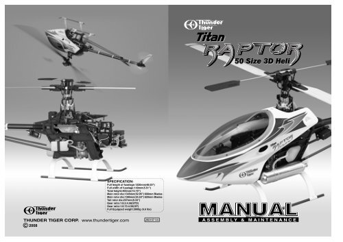
SPECIFICATION:<br />
Full length of fuselage:1220mm(48.03")<br />
fuselage:1200mm(47.24")<br />
Full width of fuselage:140mm(5.51")<br />
Total height:400mm(15.75")<br />
Main rotor dia:1345mm(52.95") 600mm Blades<br />
Main rotor dia:1385mm(54.53") 620mm Blades<br />
Tail rotor dia:237mm(9.33")<br />
Gear ratio:1:8.5:4.56(STD)<br />
Gear ratio:1:8.73:4.56(OP)<br />
Full Equipped weight:3000g (6.6 lbs)<br />
THUNDER TIGER CORP. www.thundertiger.com<br />
C 2008<br />
JK0157 V4<br />
A S S E M B L Y & M A I N T E N A N C E
INTRODUCTION<br />
Congratulations on your purchase of the Thunder Tiger Raptor 50 Titan Version helicopter. This<br />
model was designed and engineered by the world-renowned Mr. Shgetada Taya. It combines<br />
elements of his previously successful designs with today’s advanced technologies.<br />
Raptor 50 , already the best 50 class 3-D helicopter is now even better. The Raptor 50 Titan is<br />
the culmination of all customers’ feedback and tremendous research and development effort by<br />
the Thunder Tiger design team. The Raptor 50 Titan is more rugged and has improved flying<br />
performance than the previous Raptor 50 V2. The Raptor 50 Titan has the best power-to-weight<br />
ratio of any 50 class helicopters on the market. So get ready for incredibly fast accelerations<br />
and climb rate. With the new upgrades, 3-D pilots will enjoy executing crisp maneuvers like<br />
Climbing Tic-Tocs, Chaos, Death Spirals, or any radical maneuver that you can dream of. Key<br />
new features include new push-pull pitch lever, push-pull elevator lever, metal rear servo plate,<br />
hardened main shaft, stronger mainframes, bigger fuel tank, reinforced pitch control arm, and<br />
new main rotor with 6mm spindle featuring larger radial and thrust bearings. The Raptor 50 Titan<br />
includes a constant drive autorotation gear to allow aerobatics during autorotation. Beginners<br />
and advanced 3-D fliers will be impressed with the new Raptor 50 Titan.<br />
CONTENTS<br />
Introduction......................................... p.1<br />
Contents..............................................p.1<br />
Warnings............................................. p.1<br />
Additional Items Needed.....................p.3<br />
Tools Needed...................................... p.3<br />
Assembling Section............................ p.4<br />
Linkage Set-up Section.......................p.23<br />
Blade Modification...............................p.32<br />
Parts List Section................................ p.34<br />
WARNING<br />
This radio controlled helicopter is not a toy. It is a sophisticated piece of equipment and<br />
is designed for hobby use only. If not properly assembled and operated, it is capable of<br />
causing property damage and bodily harm to both the operator and spectators. Thunder<br />
Tiger and its duly authorized distributors assume no liability for damage that could occur<br />
from the assembly or operation of this product.<br />
AMA INFORMATION<br />
Operating a model helicopter requires a high degree of responsibility and skill. If you<br />
are a newcomer to the hobby, it is best to seek help and guidance from accomplished<br />
model helicopter pilots. This will greatly speed up the learning process and have you<br />
flying successfully in a reasonable amount of time. We also would strongly urge you to<br />
join the Academy of Model Aeronautics. The AMA is a non-profit organization that provides<br />
its members with a liability insurance plan as well as monthly magazine entitled Model<br />
Aviation. All AMA charter aircraft clubs require all pilots to hold a current AMA sporting<br />
license prior to operation of their models at club fields. For further information, contact<br />
the AMA at:<br />
Academy of Model Aeronautics<br />
5151 East Memorial Drive<br />
Muncie, IN 47302<br />
(317) 287-1256<br />
1
FLIGHT SAFETY CHECKLIST<br />
1. Make sure both the transmitter and receiver batteries are fully charged prior to operating the<br />
helicopter.<br />
2. Make sure all flight controls operate properly prior to flying.<br />
3. Range check the radio before the first flight. The servos must operate properly with the<br />
transmitter antenna collapsed at a range of at least 50 ft.(15 meters).<br />
4. Check to make sure there is no radio interference on your radio freguency before operating<br />
the helicopter.<br />
5. Use only the recommended engine fuel as specified by the engine manufacturer.<br />
6. Make sure the transmitter and receiver are turned on before starting the engine.<br />
7. The engine throttle must be in the idle position before starting the engine.<br />
8. Model helicopter main and tail rotors operate at very high RPM. Make sure nothing can come<br />
in contact with the rotor blades during flight.<br />
9. After starting the helicopter, maintain a safe distance during the flight.<br />
10. Never operate the helicopter in rain or excessive wind conditions.<br />
11. Always operate and fly your helicopter in a safe and responsible manner.<br />
12. Never fly a model helicopter over other pilots, spectators, cars, or anything that could result<br />
in injury or property damage.<br />
POST FLIGHT INSPECTION<br />
1. Inspect the model thoroughly to insure no parts have come loose or become damaged during<br />
the flight and landing. Replace damaged parts and tighten loose screws before flying again.<br />
2. Pump out any remaining fuel from the fuel tank.<br />
3. Wipe off excess oil and fuel from helicopter body and other exposed parts.<br />
4. Lubricate all moving parts to ensure smooth operation for the next time you fly.<br />
5. Store model in a cool, dry place. Avoid storage in direct sunlight or near a source of heat.<br />
6. Replace any loose ball links and damaged bearings.<br />
Following these few, simple safety rules will allow you to enjoy the thrill of model helicopter flying<br />
for many years to come.<br />
CAUTION: In the event the model has crashed, inspect the flybar, rotor shaft and the blade spindle<br />
to make sure they are not bent. If any item is damaged, it must be replaced with a new part to ensure<br />
safe operation. Do not glue any broken or damaged plastic parts. Do not repair broken rotor blades.<br />
Always inspect the following items immediately:<br />
Engine starting shaft.<br />
All gears, Ball links, Link rods, bearings.<br />
Main shaft, flybar and blade spindle.<br />
Tail boom and support.<br />
Vertical and horizontal fins.<br />
Tail rotor shaft and control system.<br />
Main and tail rotor blades.<br />
2
RADIO SET<br />
OTHER ITEMS REQUIRED<br />
Receiver<br />
Battery<br />
1000mAh<br />
Switch harness<br />
Transmitter<br />
(helicopter type only<br />
6 or more channels)<br />
ENGINE<br />
Servo x 5<br />
Gyro<br />
Fuel Pump<br />
HELI ENGINE(50-size)<br />
Glow Plug<br />
Glow Fuel(15%-30%)<br />
1.5V Glow starter<br />
(1.2V~1.5V)<br />
12V Electric starter<br />
Foam<br />
Extended 6mm Hex<br />
Starting Tool<br />
12V Battery<br />
Remote Glow Plug<br />
Extension<br />
Rubber Band<br />
Glow Plug Wrench<br />
Screw Driver<br />
TOOLS REQUIRED FOR <strong>ASSEMBLY</strong><br />
Needle Nose Pliers 5.5mm Wrench Ball Link Pliers Nipper Scissors<br />
Metric<br />
4-way Wrench<br />
5.5mm<br />
7mm<br />
8mm<br />
7mm<br />
Hobby Knife<br />
Instant Glue<br />
Blue Locktite<br />
Grease<br />
Epoxy<br />
Hex Wrench<br />
5.5mm<br />
7mm<br />
8mm<br />
10mm<br />
Socket Drivers<br />
3
ASSEMBLING SECTION<br />
Most parts in the Raptor kit are packed according to the assembly steps. The part number and quantity contained<br />
in each step are always shown in the square box on each page. Do not open all the bags at once. Open only<br />
the bag that is needed for the current assembly step.<br />
4
1 Fuel Tank Assembly<br />
Note: After assembly, check to make sure the Fuel Tank<br />
clunk can move from top to bottom without touching the<br />
back of tank. Also, a fuel filter (available from any hobby<br />
shop, TTR1165C) should be placed between the fuel tank<br />
and the carburetor.<br />
It might be necessary to inspect and replace the silicone<br />
tube inside the tank every month to ensure the fuel<br />
consumption is smooth.<br />
(3 )<br />
To Header Tank<br />
Connect the fuel tube to<br />
header tank<br />
(See Page 17 Step.17)<br />
(6)<br />
(2 )<br />
(5 )<br />
(6)<br />
(4 )<br />
TTR1165C FUEL FILTER<br />
Not included in the kit<br />
To Muffler<br />
(1) BK0605 Fuel Tank .....................1<br />
(2) BK0062 Fuel Tank Grommet......1<br />
(3) BK0463 Fuel Tank Nipple ..........1<br />
(4) BE1867 Clunk.............................1<br />
(5) CB0363-1 Silicone Fuel Tube.....1<br />
(6) BB0362-2 Silicone Fuel Tube.....2<br />
(1)<br />
The fuel tank comes<br />
assembled allready.<br />
2 Clutch Bell Assembly<br />
(1)<br />
(1) HMV1680 Bearing (d8xD16xW5)......1<br />
(2) HMV1360ZZY Bearing (d6xD13xW5)...1<br />
(3) BK0838 Clutch Bell...........................1<br />
(4) BK0624 Drive Gear(Pinion 10T).......1<br />
(5) BK0887 Clutch Liner.........................1<br />
(4)<br />
Add Loctite and tighten<br />
(3)<br />
(2)<br />
(5) The liner comes glued in the<br />
clutch bell already.<br />
5
3 Main Frame Assembly-Part1<br />
Please insert the frame spacers, bearings, pulley and parts in the frames according the drawing below. Install four<br />
metal aluminum frame spacers beside the main shaft bearings. Remember add Loctite when securing on these four<br />
spacers. Tighten the screws snugly, but do not over torque them which could strip the plastic.<br />
Insert starter shaft through the center of the clutch bell assembly, through the top starter shaft bearing and into the<br />
starter coupling. Secure with the two set screws. Make sure this is tightly secured.The main frame can be reinforced<br />
by recommended Aluminu Frame Post (PV0104).<br />
(1) HSE3-12B Self Tapping Screw (M3x12)....22<br />
(2) HMV696Z Bearing (d6xD15xW5)................1<br />
(3) HMV6800 Bearing (d10xD19xW5)..............2<br />
(4) BK0059 Frame Spacer (S)..........................4<br />
(5) BK0058 Frame Spacer (L).......................... 4<br />
(6) HME4-5B Set Screw (M4x5)....................... 2<br />
(7) BK0081 Pin................................................. 2<br />
(8) BK0057 Servo Frame..................................1<br />
(9) BK0599 Main Frame Left Side.................... 1<br />
(10) BK0600 Main Frame Right Side................1<br />
(11) BV0035 Guide Pulley.................................2<br />
(12) BK0036 Pulley Collar................................ 4<br />
(13) BK0592 Starter Shaft................................ 1<br />
(14) BK0594 Starter Coupling...........................1<br />
(15) Fuel Tank Assembly<br />
(16) Clutch Assembly<br />
(17) HMS5 E-Clip............................................ 1<br />
(18) BK0584 Thrust Washer.............................1<br />
(19) CK0136 Metal Frame Spacer(S)...............4<br />
(20) HSA3-10 Socket Screw(M3x10)............... 8<br />
(20)<br />
(14)<br />
(6)<br />
(19)<br />
(10)<br />
(5)<br />
(1)<br />
(2)<br />
(12)<br />
(7)<br />
(11)<br />
(4)<br />
(3)<br />
(16)<br />
(8)<br />
(17)<br />
(18)<br />
(9)<br />
(13)<br />
(15)<br />
6
4 Main Drive Gear Assembly<br />
(2)<br />
It is necessary to add grease inside the one way clutch before your<br />
first flight. The clutch might lock up once grease is gone. The one<br />
way grease( PV0517) or Ball differential grease is recommended for<br />
this lubrication.<br />
(1) HMC3-8B Socket Screw (M3x8).................4<br />
(2) HMQ14 Snap Ring..................................... 2<br />
(3) BV0033 One Way Clutch Housing............. 1<br />
(4) BK0148 Main Spur Gear 85T......................1<br />
(5) BK0610 Autorotation Tail Drive Pulley........1<br />
(6) BK0034 One Way Clutch Shaft.................. 1<br />
(3)<br />
(4)<br />
Add a drop of Blue Locktite on the<br />
thread of each of these four screws.<br />
(1)<br />
(6)<br />
(2)<br />
(5)<br />
5 Washout Assembly<br />
Make sure linkage balls are attached to the<br />
inside hole of each flybar control lever.<br />
(1) HMJ2-10N Self Tapping Screw(M2x10).. 2<br />
(2) HMC3-10B Socket Screw (M3x10)......... 2<br />
(3) HMV740ZZY Bearing (d4xD7xW2.5).......4<br />
(4) BK0077 Collar ........................................ 2<br />
(5) BK0171 Pin............................................. 2<br />
Outer hole is recommended<br />
for 3D flying.<br />
(2)<br />
(6) BK0075 Linkage Ball.............................. 2<br />
(4)<br />
(7) BK0015 Flybar Control Lever.................. 2<br />
(8) BK0016 Washout Linkage ..................... 2<br />
(9) BK0014 Washout Base............................1<br />
(6)<br />
(7)<br />
(3)<br />
(10) HMS15 E Ring ...................................... 2<br />
(10)<br />
(5)<br />
(1)<br />
(3)<br />
(3)<br />
(5)<br />
(8)<br />
(9)<br />
(10)<br />
(1)<br />
(2)<br />
(4)<br />
(3)<br />
(6)<br />
(8)<br />
(7)<br />
7
6 Main Frame Assembly-Part2<br />
Please complete subassemblies 6-1 through 6-4, them add them to the main frame.<br />
Insert the completed elevator control arm subassembly 6-1 in between upper bearing frame first. Then fit<br />
the plastic pitch control frame subassembly. Next insert elevator arm control shaft and elevator parallel<br />
lever subassembly. Then secure the plastic pitch control arm using self tapping screw (M3x12) and self<br />
tapping screw(M3x22). Adjust the two self tapping screw so the pitch control arm can rock freely but without<br />
excessively play. Add a drop of CA to the two screws at the pivoting point of the collective pitch control<br />
arm.Attach the linkage rod to the parallel elevator linkage balls. Finally add two plastic aileron levers and<br />
the elevator pushrod.<br />
(1)HSE3-18B Self Tapping Screw (M3x18).........4<br />
(2)HSE3-12B Self Tapping Screw (M3x12).........1<br />
(3)HMJ3-22B Self Tapping Screw (M3x22).........1<br />
(4)HMV1280ZZY Bearing (d8xD12xW3.5)..........2<br />
(5)HMV840ZZY Bearing (d4xD8xW3).................2<br />
(6)BK0076 Collar (d3xD4x10)............................. 3<br />
(7)BK0078 Collar (d3xD4x4)............................... 2<br />
(8)BK0088 Washer (d3xD5x0.5)......................... 1<br />
(9)BK0020 Elevator Arm Control Shaft............... 1<br />
(10)BK0075 Linkage Ball.....................................1<br />
(11)HMJ2-10N Self-Tapping Screw (M2x10)...... 1<br />
(12)BK0086 Ball Link...........................................2<br />
(13)BK0840 SUS Linkage Rod............................1<br />
(14)BK0017 Collective Pitch Control Arm............1<br />
(15) 6-1 Elevator Control Arm Subassembly.......1<br />
(16) 6-2 Elevator Push Pull Lever Subassembly....1<br />
(17) 6-3 Aileron Lever Subassembly ( R )...........1<br />
(18) 6-3 Aileron Lever Subassembly ( L )............1<br />
(19) 6-4 Elevator Parallel Lever Subassembly...1<br />
(15) (18)<br />
(9)<br />
(1)<br />
(4)<br />
(6)<br />
(1)<br />
(19)<br />
(4)<br />
(5)<br />
(7)<br />
(2)<br />
(1)<br />
(17)<br />
(11)<br />
(10)<br />
(7)<br />
(14)<br />
(1)<br />
(6)<br />
(5)<br />
(3)<br />
(6)<br />
(13)<br />
(16) (8)<br />
(12)<br />
(12)<br />
(13)<br />
66mm<br />
Warning, do not over-torque the self-tapping screws.<br />
8
6-1 Elevator Control Arm Subassembly<br />
(1)BK0018 Elevator Control Arm................... 1<br />
(2)BK0023 Elevator Control Arm Link........... 2<br />
(3)BK0084 Pin............................................... 2<br />
(2)<br />
INSTALLATION OF THE RODS<br />
Big Hole<br />
(1)<br />
Big Hole<br />
(3)<br />
6-2 Elevator Push Pull Lever Subassembly<br />
(1)BK0836 Elevator Push Pull Lever............. 1<br />
(2)HMV740ZZY Bearing (d4xD7x2.5)........... 2<br />
(3)BK0075 Linkage Ball.................................3<br />
(4)HMJ2-8N Self-Tapping Screw (M2x8).......3<br />
(4)<br />
(3)<br />
(1)<br />
(2)<br />
Add CA glue<br />
Outer hole is recommended<br />
6-3 Aileron Lever Subassembly<br />
Add CA glue<br />
(1)BK0022 Aileron Control Lever...................1<br />
(2)HMV740ZZY Bearing (d4xD7x2.5)............2<br />
(3)BK0075 Linkage Ball.................................2<br />
(4)HMJ2-10N Self-Tapping Screw (M2x10)...2<br />
(1)BK0022 Aileron Control Lever...................1<br />
(2)HMV740ZZY Bearing (d4xD7x2.5)............2<br />
(3)BK0075 Linkage Ball.................................2<br />
(4)HMJ2-10N Self-Tapping Screw (M2x10)...2<br />
(L)<br />
(2)<br />
(1)<br />
(3)<br />
(4)<br />
(R)<br />
(4)<br />
(3)<br />
(1)<br />
(2)<br />
Add CA glue<br />
6-4 Elevator Parallel Lever Subassembly<br />
(1)<br />
(1)BK0019 Elevator Arm Parallel Lever.........1<br />
(2)BK0075 Linkage Ball.................................1<br />
(3)HMJ2-10N Self-Tapping Screw (M2x10)...1<br />
(3)<br />
Add CA glue<br />
(2)<br />
9
7 Main Frame Assembly-Part3<br />
Insert main shaft through the shaft bearings making sure that the end with the holes closest to the end is<br />
pointed down. Next, slide main gear assembly into position on the shaft and line up the holes in the main<br />
shaft with the holes in one way clutch shaft of the main gear assembly. Insert the socket head screw and<br />
secure with the lock nut. Secure the main gear assembly just tight, do not overtorque the socket screw<br />
as it might hurt the plastic autorotation gear. Next, slide on the mainshaft lock ring on top of the main shaft<br />
bearing and secure with the two set screws. Then slide on the swashplate assembly and attach the elevator<br />
and aileron control linkages to the outside swashplate linkage balls. Next, slide on washout assembly<br />
and attach washout linkage to the inner linkage balls of the swashplate.<br />
(1) BK0616 Socket Screw(M3x20)..............1<br />
(2) HMM3Z Lock Nut (M3)..........................1<br />
(3) HME4-5B Set Screw (M4x5).................2<br />
(4) BK0086 Ball Link ..................................4<br />
(5) BK0839 SUS Linkage Rod ...................2<br />
(6) BK0030 Main Shaft Lock Ring...............1<br />
(7) BK0702 Harden Main Shaft...................1<br />
(8) Wash Out Assembly<br />
(9) BV0092 Metal Swash Plate Assembly...1<br />
(10) Main Gear Assembly<br />
(3)<br />
(7)<br />
(8)<br />
(9)<br />
(6)<br />
(4)<br />
(5)<br />
55mm<br />
(4)<br />
(5)<br />
(10)<br />
(2)<br />
(1)<br />
8 Engine Assembly<br />
Note: A piston lock (TTR 1166P) purchased from your dealer will<br />
make this a much easier task. You must replace the standard<br />
throttle arm with the extended throttle arm and attach the linkage<br />
ball.<br />
(1)<br />
(5)<br />
(2)<br />
(1) HMC3-10B Socket Screw(M3x10)..... 2<br />
(2) BV0589 Clutch Shoe..........................1<br />
(3) BV0143 Cooling Fan.......................... 1<br />
(4) No.9605 TT PRO-50H(R) Engine.......1<br />
(5) BK0170 Shim.....................................1<br />
(6) BK0075 Link Ball................................1<br />
(7) HMF2-8N Screw(M2x8)..................... 1<br />
(8) HML2 Hex Nut (M2)........................... 1<br />
Add Blue Loctite<br />
(4)<br />
Tighten the engine<br />
nut securely by<br />
grabbing the plastic<br />
fan with a towel.<br />
(3)<br />
Linkage Ball to<br />
throttle Arm<br />
(8)<br />
(6)<br />
(7)<br />
10
9 Main Frame Assembly-Part4<br />
Add blue Loctite to all metal to metal screw surfaces.<br />
After installing the engine, connect the silicone fuel tube<br />
to the carburator and muffler.<br />
(1) HMC3-14B Socket Screw(M3x14).....10<br />
(2) HMC3-35B Socket Screw(M3x35)...... 2<br />
(3) BK0087 Flat Washer............................6<br />
(4) BK0144 Engine Mount.........................1<br />
(5) BV0172 Muffler....................................1<br />
(6) Engine Assembly<br />
(7) BA1579 Muffler Gasket........................1<br />
(8) BK0179 Spacer....................................2<br />
(9) HMT3B Spring Washer........................2<br />
Engine Mount Notes:<br />
The engine mount furnished will accommodate the Thunder Tiger 50H,<br />
and the other heli engines. If you are installing a Thunder Tiger engine,<br />
you will find the mount is wider than the engine crankcase. Two spacers<br />
are furnished to accurately locate the engine while bolting it in place.<br />
Remove these spacers after installation.<br />
(1)<br />
(6)<br />
(9)<br />
(2)<br />
Add Blue Locktite<br />
(3)<br />
(1)<br />
Add Blue<br />
Loctite<br />
(4)<br />
Spacer<br />
Step1<br />
Install the engine and<br />
spacers into the engine<br />
mount.<br />
Step2<br />
Install the 4 mount screws<br />
and make sure the screws<br />
are tighten firmly.<br />
Step3<br />
Remove the spacers.<br />
(8)<br />
(1)<br />
(7)<br />
(5)<br />
10 Landing Skid Assembly<br />
(1) HSE3-18B Self Tapping Screw(M3x18).4<br />
(2) HME4-5B Set Screw(M4x5)..................4<br />
(3) BK0066 Skid Brace...............................2<br />
(4) BK0064T Skid Pipe...............................2<br />
(5) BK0065 Skid Pipe End Cap..................4<br />
(3)<br />
(2)<br />
(1)<br />
(2)<br />
(4)<br />
The optional Thunder Tiger Remote Glow Plug<br />
Adaptor(#3803) is recommended as shown, making<br />
starting easier without the removal of your canopy.<br />
(5)<br />
11
11 Main Rotor Head Assembly<br />
Secure the linkage ball on the Main Rotor Pitch Housing first then insert the Flap Damper in the Main Rotor Hub.<br />
Add Silicon Oil or Vaseline to insert the Feathering Shaft through the Flap Dampers. There is also an optional red<br />
80 degree durometer hard damper PV0382 for 3D flying.<br />
Apply Loctite on the M4x8 socket screw then secure the Main Rotor Pitch Housing on the Feathering Shaft with<br />
bearings and washers tightly.<br />
For extreme 3D flying, we would recommemd our optional Metal Main Rotor Hub (PV0338) or Metal Button Main<br />
Rotor Hub (PV0484).<br />
(1)BK0012 Pin............................................... 2<br />
(2)BK0435 Washer (d4xD11xW1.7).............. 2<br />
(3)HMV1360ZZY Bearing (d6xD13xW5)....... 4<br />
(4)BK0584 Thrust Washer.............................2<br />
(5)HMX0612 Thrust Bearing..........................2<br />
(6)BK0596 Main Rotor Pitch Housing............2<br />
(7)BK0583 Feathering Shaft..........................1<br />
(8)BK0581 Flap Collar................................... 2<br />
(9)BK0586 Flap Damper (70')........................2<br />
(10)BK0007 Flybar Control Rod.................... 2<br />
(11)BK0587 Main Rotor Hub Pin................... 1<br />
(12)BK0595 Main Rotor Hub......................... 1<br />
(13)HMC4-8B Socket Screw (M4x8)............. 2<br />
(14)BK0075 Linkage Ball...............................2<br />
(15)HMJ2-10N Self Tapping Screw (M2x10)..2<br />
(10)<br />
(12)<br />
(3) (8)<br />
(6) (7)<br />
(9)<br />
(2)<br />
(3)<br />
(4) (5)<br />
(13)<br />
Add Blue Locktite<br />
(14)<br />
(15)<br />
(1)<br />
(11)<br />
(5) HMX0612<br />
Large Internal Diameteralways<br />
go toward the<br />
Main Rotor Hub<br />
Small Internal Diameteralways<br />
go toward the<br />
Blade<br />
Diagram for Thrust Bearing Assembly<br />
12
12 Flybar Assembly<br />
Begin by attaching six Linkage Balls to the Flybar Control Arm and Mixing Lever with Self Tapping Screw. Slide<br />
Flybar Arm Bushing and Flybar Control Arm onto the Flybar Rod. From the other end of the Flybar Rod, slide on<br />
the Flybar Seesaw Hub. Make sure the Flybar has equal protruding from each side of the Seesaw Hub, then install<br />
and tighten the HME4-5B set screws. Add the Paddles. Make sure the two Paddles and the two Flybar Control Arms<br />
are all parallel. Lock the Paddles with HME3-10B set screws.<br />
Attaching four Linkage Balls to the Mixing Levers first. Then assemble and install the Mixing Levers ,Bearings and<br />
washers using Collar with Socket Screw. Be careful don’t let the Loctite seep into the bearings.<br />
Attach the Bearings into the Main Rotor Hub. Insert and tighten the Set Screws. Attach the Flybar Control Rod to<br />
the Flybar Control Arm and use the Double Link to connect the mixing Lever (short side) to the Main Rotor Pitch<br />
Housing.<br />
Note:The equipped with Paddle is good for stable and beginner flying. For those aggressive 3D pilots, we would<br />
recommend our optional light 3D Paddle (PV0481) or ultra light Paddle (PV0482) which weights only 25g and 20g.<br />
(1)BK0002 Flybar Control Arm....................... 2<br />
(2)BK0004 Flybar Seesaw Hub...................... 1<br />
(3)BK0005 Flybar Arm Bushing......................2<br />
(4)BK0006 Mixing Lever................................. 2<br />
(5)BK0067 Flybar Paddle............................... 2<br />
(6)BK0075 Linkage Ball..................................6<br />
(7)BK0076 Collar (d3xD4x10)........................ 2<br />
(8)BK0078 Collar (d3xD4x4).......................... 2<br />
(9)BK0088 Washer (d3xD5x0.5).................... 2<br />
(10)BK0631 SUS Flybar............................... 1<br />
(11)BV0085 Double Link................................ 2<br />
(12)HMC3-14B Socket Screw (M3x14).......... 2<br />
(13)HMC3-8B Socket Screw (M3x8).............. 2<br />
(14)HME3-10B Set Screw (M3x10)................ 2<br />
(15)HME4-5B Set Screw (M4x5).................... 2<br />
(16)HMJ2-10N Self Tapping Screw (M2x10)..6<br />
(17)HMV740ZZY Bearing (d4xD7x2.5)...........4<br />
(18)HMV840ZZY Bearing (d4xD8x3)..............2<br />
(19)Main Rotor Head Assembly......................1<br />
(5)<br />
(15)<br />
(1)<br />
(17)<br />
(7)<br />
(9)<br />
(6) (2)<br />
(16)<br />
(10)<br />
(3)<br />
(14)<br />
(4)<br />
(18)<br />
(8)<br />
(12)<br />
(11)<br />
(13)<br />
(19)<br />
13
13 Main Frame Assembly-Part5<br />
Slide the main rotor assembly over the main shaft and align the two pins to<br />
slide in the washout assembly. Make sure the holes in the main shaft line<br />
up with the holes in the main rotor head. Insert the socket screw and secure<br />
with locknut. Attach the ball linkage rods to the long end of the mixing lever<br />
and to the remaining inside linkage balls of the swashplate.<br />
(1) BK0616 Socket Screw(M3x20)..... 1<br />
(2) HMM3Z Lock Nut(M3)........................1<br />
(3) HME3-18.5B Set Screw(M3x18.5)......2<br />
(4) BK0842 SUS Linkage Rod................ 2<br />
(5) BK0086 Ball Link............................... 4<br />
(6) BK0626 Canopy Retaining Post........ 2<br />
(7) Main Rotor Head Assembly<br />
(5)<br />
(4)<br />
100mm<br />
(7)<br />
(2)<br />
(5)<br />
(4)<br />
(1)<br />
(6)<br />
(3)<br />
(3)<br />
(6)<br />
14
14 Tail Unit Assembly<br />
Secure the tail rotor hub(#11) on tail rotor shaft first, note the Set Screw(#3) should be right setting on the dot of the<br />
shaft. Do not forget to apply Loctite on the Set Screws. Do not over tighten the locknut(#4) with the two bearings.<br />
Next work on the housing assembly, use care to install the Tail Pitch Control Link, do not over tighten the selftapping<br />
Screw(#2). Make sure it is just tight and the link rotates freely.<br />
Assemble the Tail Pitch Slider and Fork. Be careful when securing the Fork on the slider bushing, do not damage<br />
the bushing or it will not move smoothly on the tail rotor shaft.<br />
(1)HMC2510B Socket Screw(M2.5x10)......4<br />
(2)HSE2-10B Selftapping Screw(M2x10)....2<br />
(3)HME3-18.5B Set Screw(M3x18.5)..........2<br />
(4)HMM3Z Lock Nut(M3).............................2<br />
(5)HMV1050ZZO Angular Bearing(d5xD10x4)...4<br />
(6)HMV1060ZZY Bearing(d6xD10xW3)......2<br />
(7)BK0082 Collar(d2xD3xW4.3)..................2<br />
(8)BK0546 Pin(2mm)...................................2<br />
(9)BK0302-1 Tail Pitch Housing(A)..............2<br />
(10)BK0303-1 Tail Pitch Housing(B)............2<br />
(11)BK0307 Tail Rotor Hub..........................1<br />
(12)BK0026 Tail Pitch Control Link..............2<br />
(13)BK0025 Tail Pitch Control Fork.............1<br />
(14)BK0027 Tail Pitch Control Slider...........1<br />
(15)BK0028 Tail Pitch Control Slide Bushing.....1<br />
(16)BK0053 Tail Rotor Shaft........................1<br />
(17)HMM25 Lock Nut(M2.5)........................4<br />
(18)BK0075 Link Ball...................................1<br />
(19)HMF2-8N Screw(M2x8).........................1<br />
(20)HMS15 E Ring.......................................4<br />
Red Side In<br />
Black Side Out<br />
(4)<br />
(3)<br />
(5)<br />
(9)<br />
(17)<br />
(11)<br />
Warning:<br />
Please note the assembling direction of<br />
the angular bearing. If they are not<br />
assembled properly as illustrated, they will<br />
easily fail and result in unexpected danger.<br />
(10)<br />
(8)<br />
(20)<br />
(16)<br />
(1)<br />
(12)<br />
(7)<br />
(2)<br />
(15)<br />
(18)<br />
(6)<br />
(14)<br />
(13)<br />
(19)<br />
15 Tail Unit Assembly<br />
Secure the Pulley by pressing the pin into the tail rotor shaft. Apply Loctite<br />
on set screw then secure the pin with the set screw in place firmly.<br />
Secure the Tail Pitch Control Lever just tight and make sure it rotates freely.<br />
(1) HMV1150X Bearing (d5xD11xW5)........ 1<br />
(2) HMY2-12 Pin(2x12)............................... 1<br />
(3) HSE3-18B Self Tapping Screw(M3x18)....... 1<br />
(4) HMF2-8N Screw(M2x8).........................1<br />
(5) BK0076 Collar(3x4x10)..........................1<br />
(6) BK0075 Link Ball................................... 1<br />
(7) HMV740ZZY Bearing (d4xD7xW2.5).....2<br />
(8) BK0024 Tail Pitch Control Lever............ 1<br />
(9) BK0088 Flat Washer..............................1<br />
(10) HME3-4B Set Screw(M3x4)................ 1<br />
(11) BK0050 Tail Pulley............................... 1<br />
(12) BK0051 Tail Pulley Flange...................1<br />
(13) BK0047 Tail Unit Housing (R)..............1<br />
(14) Tail Unit Assembly<br />
(2)<br />
(11)<br />
(10)<br />
Add Loctite<br />
(12)<br />
(6)<br />
(4)<br />
(1)<br />
(13)<br />
(9)<br />
(7)<br />
(8)<br />
(7)<br />
(5)<br />
(14)<br />
(3)<br />
15
16 Tail Boom Assembly<br />
Assembly Tip: Slide the 3 rod guides onto the boom and space them out evenly as shown. Then slide the tail linkage<br />
rod into the rod guides. Next, insert the tail rotor drive belt into the boom so that it comes out of both ends. Place<br />
drive belt over tail drive pulley and complete balance of tail boom assembly. Remember to connect the tail linkage<br />
rod to the tail control lever. Apply thick CA or Epoxy when installing Tail support Rod End.<br />
(1) HMC3-20B Socket Screw(M3x20)............. 4<br />
(2) HMC3-25B Socket Screw(M3x25)............. 2<br />
(3) HSE3-12B Self Tapping Screw(M3x12)..... 4<br />
(4) HMM3Z Lock Nut(M3)................................6<br />
(5) HMV1150X Bearing (d5xD11xW5)............. 1<br />
(6) BK0071 Vertical Fin....................................1<br />
(7) BK0069 Stabilizer Fin.................................1<br />
(8) BK0046 Tail Unit Housing...........................1<br />
(9) BK0524T Tail Support Rod.........................2<br />
(10) BK0070 Stabilizer Fin Bracket..................1<br />
(11) BK0859 Tail Boom.................................... 1<br />
(12) BK0091 Rod Guide.................................. 3<br />
(13) BK0858 Tail Rotor Drive Belt... ................1<br />
(14) BK0860 Tail Linkage Rod.........................1<br />
(15) BK0447 Tail Support Rod End................. 4<br />
(16) HMJ2-8N Seif Tapping Screw(M2x8)....... 4<br />
(17) BK0086 Ball Link......................................2<br />
(18) BV0052 Tail Idle Pulley.............................1<br />
(19) Tail Unit<br />
(17)<br />
(1)<br />
(19)<br />
(2)<br />
(3)<br />
(18)<br />
(5)<br />
(8)<br />
(4)<br />
(4)<br />
(11)<br />
(7)<br />
(12)<br />
(14)<br />
(6)<br />
(10)<br />
(17)<br />
(3)<br />
(13)<br />
(9)<br />
Add CA glue<br />
(15)<br />
(16)<br />
16
17 Main Frame Assembly-Part6<br />
Insert the M3x20 and two M3x25 socket screws with meatal Rear Servo Plate into the tail base of the Main Frame<br />
and secure with lock nuts. Do not tighten at this point.<br />
Hold the tail boom in one hand and hook your index finger on your free hand through the exposed loop of the tail<br />
rotor drive belt. Hold it so the belt is vertical and parallel to the tail drive pulley.<br />
Boom Drive belt<br />
Important: Next, rotate the belt 90-degree counter clockwise.<br />
90-degree<br />
Tail Rotor Rotate Direction<br />
(6)<br />
(1)HMC3-14B Socket Screw (M3x14)..............3<br />
(2)HMC3-20B Socket Screw (M3x20)..............2<br />
(3)HMC3-25B Socket Screw (M3x25)..............2<br />
(4)HSE3-12B Self-Tapping Screw (M3x12)..... 2<br />
(5)HMM3Z Lock Nut (M3)................................ 6<br />
(6)BK0068 Tail Rotor Blade............................. 2<br />
(7)BV0502 Header Tank.................................. 1<br />
(8)BK0506 Tank Mount....................................1<br />
(9)BK0087 Washer.......................................... 1<br />
(10)BK0837 Metal Rear Servo Plate................1<br />
(11)Tail Assembly............................................ 1<br />
(5)<br />
(11)<br />
(5)<br />
(2)<br />
(3)<br />
(1)<br />
(5)<br />
(4)<br />
(10)<br />
(1)<br />
(9)<br />
(8)<br />
(7)<br />
Pull the belt through the tail base, keeping the belt correctly aligned. Push<br />
the tail boom into the tail base all the way to the end. Place the drive belt over<br />
the tail drive spur gear. Then, gently pull back on the tail boom until the tension<br />
on the belt allows no more than 5mm(3/16") of free play in the belt. Tighten<br />
the locknuts and proceed with the rest of the assembly.<br />
Install the header tank and secure the mount with socket screw, washer.<br />
Connect the fuel tube properly.<br />
17
18 Servo Installation-Part1<br />
Assembly Tip: Remove all the servo wheels prior to attaching the steel linkage balls.<br />
Make sure all linkages are the correct length.<br />
(1)HSE2612N Self Tapping Screw(M2.6x12)......4<br />
(2)HSE2620N Self Tapping Screw(M2.6x20)......4<br />
(3)BK0075 Linkage Ball.......................................5<br />
(4)BK0086 Ball Link.............................................9<br />
(5)BK0104 Servo Mounting Plate........................6<br />
(6)BK0105 Tail Control Rod Joint........................1<br />
(7)BK0474 Rubber CAP...................................... 2<br />
(8)BK0832 Body Support.....................................1<br />
(9)HNLR6 R Pin...................................................2<br />
(10)BK0833 Servo Block..................................... 2<br />
(11)BK0840 SUS Linkage Rod (M2.3x46).......... 2<br />
(12)BK0843 SUS Push Rod A.............................1<br />
(13)BK0845 SUS Linkage Rod (M2.3x64)...........2<br />
(14)HMC2516B Socket Screw (M2.5x16)........... 4<br />
(15)HME4-5B Set Screw (M4x5).........................2<br />
(16)HMF2-8N Screw (M2x8)................................5<br />
(17)HML2 Nut (M2) ............................................ 5<br />
(18)HMM25 Lock Nut (M2.5)...............................4<br />
(11)<br />
(4)<br />
Before installing Aileron<br />
Servo, tape the wire as<br />
shown.<br />
Futaba<br />
Loctite<br />
70~73mm<br />
(16)<br />
Mount the Steel<br />
Linkage Balls at 10.<br />
5mm(approx 7/16")<br />
from the center of the<br />
servo horn.<br />
(11)<br />
(4)<br />
(3)<br />
(17)<br />
(18)<br />
(1)<br />
(5)<br />
Aileron Servo<br />
(14)<br />
Rudder Servo<br />
(5)<br />
(10)<br />
Elevator Servo<br />
(5)<br />
(13)<br />
(4)<br />
(2) (7)<br />
(9)<br />
(8)<br />
(13)<br />
If you choose the rear servo plate to assembly, don't need to use #6, #12, #15.<br />
18
19 Servo Installation-Part2<br />
Assembly Tip: Remove all the servo wheels prior to attaching the steel<br />
linkage balls. Make sure all linkages are the correct length.<br />
See Engine-Throttle Control Linkage in page 22.<br />
(1)HSE2612N Self Tapping Screw(M2.6x12).....8<br />
(2)HSE2620N Self Tapping Screw(M2.6x20).....4<br />
(3)BK0104 Servo Mounting Plate.......................4<br />
(4)BK0833 Servo Block...................................... 2<br />
(5)BK0834 Pitch Lever Fixed Plate.....................1<br />
(6)HMC3-18 Socket Screw (M3x18)...................1<br />
(7)BK0113 Linkage Rod (M2.3x18)....................2<br />
(8)BK0085 Ball Link............................................4<br />
(9)BK0086 Ball Link............................................4<br />
(10)BK0839 SUS Linkage Rod (M2.3x30)..........1<br />
(11)BK0841 SUS Linkage Rod (M2.3x60)..........1<br />
(12)BK0075 Linkage Ball....................................4<br />
(13)HMF2-8N Screw (M2x8)...............................4<br />
(14)HML2 Nut (M2)............................................ 4<br />
Mount the Steel Link<br />
Ball at 10.5mm(approx<br />
7/16") from the center<br />
of the servo horn for<br />
the throttle arm.<br />
Futaba<br />
(9)<br />
(10)<br />
(9)<br />
(6)<br />
(8)<br />
(10) 45mm (7)<br />
(5)<br />
(1)<br />
(4)<br />
(2)<br />
(8)<br />
(7)<br />
30mm<br />
(3)<br />
(1)<br />
Pitch Linkage Rod Subassembly.<br />
(5)<br />
(11)<br />
(9)<br />
(4)<br />
(9)<br />
(3)<br />
(2)<br />
(1)<br />
(1)BK0835 Pitch Push-Pull lever................1<br />
(2)HMV740ZZY Bearing (d4xD7xW2.5)....2<br />
(3)BK0075 Linkage Ball.............................3<br />
(4)HMJ2-8N Self Tapping Screw(M2x8)....3<br />
(5)BK0846 Collar (d3xD4x8.5)...................1<br />
75mm<br />
(11)<br />
Pitch push-pull lever subassembly.<br />
Throttle linkage Rod subassembly.<br />
19
20 Receiver/Gyro Installation<br />
Thunder Tiger recognizes that there are many brands of radios and gyros to choose from. You are encouraged to<br />
seek the advice of experienced helicopter pilots when making this decision.<br />
(1) BE1052 Antenna Tube...................1<br />
(2) BK0106 Double Side Tape............ 2<br />
On/Off Switch Face Plate<br />
Thunder Tiger TG-8000<br />
piezo gyro and TG-7000<br />
lock gyro is commended<br />
(2)<br />
On/Off Switch<br />
Gyro Amplifier<br />
(2)<br />
Receiver<br />
(2)<br />
Battery Pack<br />
(2)<br />
21 Body/Canopy Assembly<br />
(1)<br />
Cut off the bubble from the body leaving the lip all the way<br />
around. Neatness counts, so take your time. Next trim the<br />
flange from the canopy leaving a clean edge. You can lightly<br />
sand the edges to get it smooth and even. On the lip of the<br />
opening in the body, mark six points for drilling holes to secure<br />
canopy: 1-in front, 1-in rear and 2 on each side.<br />
Using double stick tape secure canopy to body. Take a very<br />
sharp awl and make pilot holes through the canopy and body<br />
lip. Make sure all holes line up. Remove double stick tape<br />
and put in the self tapping screws. Install the body clip, decals,<br />
and rubber grommets.<br />
(1)<br />
(4) (7)<br />
(1) HMJ2-6B Self Tapping Screw(M2x6)......7<br />
(2) HSE3-12B Self Tapping Screw(M3x12)........ 2<br />
(3) BK0611 Body.......................................... 1<br />
(4) BK0102 Rubber Grommet ..................... 2<br />
(5) BK0098 Body Clip-A...............................1<br />
(6) BK0099 Body Clip-B...............................1<br />
(7) BK0612 Canopy......................................1<br />
Body<br />
Grommet<br />
Trim the hole and install the<br />
rubber grommets as shown.<br />
(3)<br />
(6)<br />
(5)<br />
(2)<br />
If the Body will fall out during<br />
backward 3D flying, we suggest<br />
to install the self tapping scew (#1)<br />
on Body Clip-A (#5).<br />
20
22 Main Rotor Assembly<br />
The 600mm wood blades come with the kit, however, we suggest to use wood blade for Hovering only. Make<br />
sure you do the blade modification as page 32 instructed before you fly.<br />
For F3C or 3D flying, we strongly recommend using Carbon or Fiberglass rotor blades for safety and higher<br />
performance.<br />
Important-While Thunder Tiger takes great care to manufacture the most balanced blades available, no two rotor<br />
blades are exactly the same. It is highly recommended that you purchase a blade balancer from your hobby dealer.<br />
Follow the manufacturer's instructions for balancing the blades and install on helicopter.<br />
(1) BV0455 Main Rotor Blade(600mm).......2<br />
(2) HMD2612B Self Tapping Screw (M2.6x12)...4<br />
(3) BK0073 Upper Blade Grip... .................. 2<br />
(4) BK0074 Lower Blade Grip..................... 2<br />
(5) HMM4Z Lock Nut(M4)............................ 2<br />
(6) HMC4-27B Socket Screw (M4x27).........2<br />
(1)<br />
(2) (3)<br />
(4)<br />
Make sure you do the blabe modification as<br />
page 32 instruction before you fiy.<br />
(6)<br />
(5)<br />
21
Engine Throttle Control Linkage<br />
Mount the steel linkage ball to the outer hole on the plastic throttle arm. At full throttle stick, the<br />
carburetor hole should open completely. At low throttle and with the throttle trim all the way down,<br />
the carburetor hole should close completely. Adjust the ATV function in your transmitter to achieve<br />
the above requirement. Listen to the servo, it should not make any binding noise. Try keep the<br />
throttle ATV between 90% and 110%. If your radio does not have ATV, then adjust the location<br />
of the steel link ball on the throttle servo horn to get the correct throttle travel.<br />
THROTTLE CLOSE<br />
THROTTLE FULLY OPEN<br />
22
LINKAGE SET-UP SECTION<br />
23
Setting up Main Rotor Blades Pitch Angle<br />
On the left side frame, there are<br />
three pitch scales molded onto<br />
the plastic frame. The three<br />
different scales are designed for<br />
beginner, intermediate or expert<br />
F3C and 3D pilots.<br />
Use the "pointer" on the collective<br />
tray and the plastic molded scales<br />
to set up the initial collective<br />
control.<br />
The actual blade angle in degrees<br />
can be checked using a pitch<br />
gauge (sold seperately).<br />
For Beginners<br />
For Intermediates<br />
For F3C or 3D<br />
Top End Pitch 11˚<br />
Hover 5.5˚<br />
Beginners -2˚<br />
Intermediates -5˚<br />
Pointer<br />
Bottem End Pitch -10˚<br />
The total pitch angle range should be at -10˚~ +11˚.<br />
24
(Hint for beginners)<br />
Pitch Push Pull Lever Adjustment<br />
Setting up Main Rotor Blades Pitch Angle<br />
Mount the Steel<br />
Linkage Ball at<br />
20mm from FUTABA the<br />
center of the Pitch<br />
Push Pull Lever.<br />
5.5˚<br />
Throttle Stick in the center<br />
position<br />
(Hint for beginners)<br />
The hoveing pitch angle should be at 5.5˚. To get the -2˚ to<br />
11˚ collective range, mount the steel linkage ball at 13~15mm<br />
away from the center of the collective servo horn.<br />
Mount the Steel<br />
Linkage Ball at<br />
13~15mm FUTABA from the<br />
center of the servo<br />
horn.<br />
5.5˚<br />
Throttle Stick in the center<br />
position<br />
5.5˚ hovering pitch angle is used for beginners, intermediates and experts. The throttle/collective must<br />
be in the center position when adjusting the collective pushrod length to make the "point" line up with the<br />
5.5˚ hover point on the molded scale(see above diagrams).<br />
25
*High End Blade Pitch Setting<br />
11˚<br />
Linkage Position for beginner<br />
11˚<br />
6˚<br />
-2˚<br />
-5˚<br />
-10˚<br />
Throttle at High Position<br />
*Move the throttle/collective stick to the full throttle position(see upper right diagram). The molded "pointer"<br />
should now line up with the upper limit mark, which should provide about 11˚ of blade pitch.<br />
*Low End Blade Pitch Setting<br />
-2˚<br />
Throttle at Low Position<br />
*Move the throttle/collective stick to the low stick position. Use the ATV function of your transmitter to<br />
make the "pointer" line up with the -2˚ mark for beginners(with the -5˚ mark for intermediates, and -<br />
10˚ mark for experts).<br />
26
Collective Travel for F3C and 3D Flying<br />
*To achieve +11˚ to -10˚ of collective travel range, the steel linkage ball must be moved to the inner<br />
location as shown in the figure.<br />
*You can also flip the pitch servo to get the best configuration.<br />
*Use ATV function of the transmittler to get the necesary servo travel.<br />
*High End Blade Pitch Setting<br />
Linkage Position for F3C or 3D<br />
11˚<br />
11˚<br />
Throttle at High Position<br />
The molded "pointer" should line up with the upper limit mark, which<br />
should provide about 11˚ of blade pitch.<br />
*Low End Blade Pitch Setting<br />
-5˚<br />
Position for F3C or 3D<br />
-5˚<br />
-10˚<br />
Throttle at Low Position<br />
For intermediates set the low end to -5˚. For advanced F3C and 3D flying,<br />
set the low end to -10˚.<br />
27
CONFIGURING THE RAPTOR FOR 3D<br />
5-Point Throttle Curves<br />
Normal 0 30 50 75 100<br />
Idle-up1 100 85 60 85 100<br />
Idle-up2 100 60 55 80 100<br />
5-Point Pitch Curves<br />
Normal 18 38 55 75 94<br />
Idle-up1 0 22 46 70 90<br />
Idle-up2 0 22 46 70 90<br />
Hold 15 38 55 75 100<br />
lengths<br />
measured from<br />
ball link center<br />
to<br />
ball link center<br />
100mm<br />
10-12mm<br />
Blade Pitch Angles (degrees)<br />
Normal -4 5.5 9.5<br />
Idle-up1 -9 0 9<br />
Idle-up2 -9 0 9<br />
Hold -6 5.5 10.5<br />
55mm<br />
The above pushrod lengths will permit 3D with the Raptor.<br />
Use these lengths as a starting point. Beginners can also use those pushrod lengths, but just connect the<br />
collective control to the outside point on the pitch control arm. Pushrod lengths are measured from ball link<br />
center to ball link center.<br />
Suggested throttle and collective pitch set up: Idle-up1 is used for continuous 3-D flips and aerobatics.<br />
Idle-up2 is used for switchless inverted hover. Use a pitch gauge to check blade angles. It is easier to start<br />
setting up idle-up2 blade pitch angles first. Beginners should inhibit idle-up1, idle-up2. Beginners should<br />
only use the Normal mode values. The model should hover at around 1550 rpm in Normal mode, and flies<br />
at 1800 in idle-up1. Rotorspeed can be checked using TTR2000 MTF-301 helicopter tachometer.With 1700<br />
or higher headspeed, the use of carbon blades is recommended.<br />
28
Radio and Control Linkage Setup For Raptor 50<br />
The performance of any RC helicopter and how well it fly depends strongly on well the model has been<br />
set up. We will go through the step-by-step on how to set up the transmitter and mechanics linkages<br />
to make your Raptor 50 fly at its best. Before you start, please make up the length of all the pushrods<br />
according to the recommended length given in our 3D setup drawing in the instruction manual. The<br />
pushrod lengths we have provided are valid for beginners to expert 3-D flying. Then, we recommend<br />
using the reset function on your transmitter to reset all settings to factory default values. Check the<br />
end point adjustment, or ATV value, on your transmitter to make sure the values are at 100%. Next<br />
we recommend program the numerical values we have provided in the table for the five points in the<br />
throttle curves and for the collective pitch curves. Now you can proceed to do the mechanical adjustments.<br />
We recommend leave the transmitter on during the following adjustments.<br />
1.Throttle Adjustment.<br />
The throttle arm on the carburetor should always be parallel to the throttle servo arm. When the throttle<br />
barrel is half open, the throttle arm should be straight down. Leave it at this position. Turn on the<br />
transmitter and leave the throttle in the Normal Throttle Mode. Set the throttle trim to the bottom and<br />
set the throttle stick to the middle. Adjust the throttle pushrod to the correct length. Check the throttle<br />
servo travel direction to confirm moving the throttle stick to the high position will move the throttle arm<br />
to the full open position. Use a medium length servo arm. Pick a hole on the servo arm so when the<br />
throttle stick is moved to the highest or the lowest position, it will fully open or fully close the throttle<br />
arm without binding. Now is the time to use the End Point Adjustment or ATV feature on the transmitter<br />
to fine tune the throttle servo travel to achieve this. Avoid using too large or too small ATV values.<br />
The ATV values should stay between 90 to 100%.<br />
2.Collective Pitch Setup<br />
Collective control makes a helicopter ascend or descend by changing the main rotor blade angle.<br />
Beginners and advance fliers must attach the collective control pushrod to different locations on the<br />
collective control arm. The difference is that advance fliers desire more collective travel range, usually<br />
+10 to -10 degrees of blade change range. Beginners only need -2 to +10 degrees of blade change<br />
range. We assume you have programmed in our recommended values from the Table for the throttle<br />
and pitch curves.<br />
Collective Setup for Beginners:<br />
Only the Normal Throttle Model will be used. We recommend using a collective pitch range of -2 to<br />
+10 degrees. Move the throttle/collective control stick to the center. Attach the servo arm so the servo<br />
arm is in a horizontal position. The servo output shaft has spline. Try mounting the servo arm with<br />
different orientation until one of the arms becomes as close to horizontal. Attach the steel ball to the<br />
collective servo arm at about 15 mm from the center of the servo arm. Move the throttle stick to the<br />
middle position. Tilt the collective control arm/tray assembly so it is approximately in the middle of its<br />
allowable mechanics tilting range. Use the molded pitch scale on the left side of the plastic frame.<br />
The pointer on the collective arm should point to the mark for the hover position. See our drawings of<br />
the molded scale in the other section of this manual. Attach the pushrod. The pushrod length should<br />
be 51 mm as recommended in the drawing. Use a pitch gauge to check the blade angle, they should<br />
be about 5.5 degrees. This is what you need for hovering. This gives a hovering rotor rpm around<br />
1500.<br />
29
Radio and Control Linkage Setup For Raptor 50<br />
Move the throttle stick to the high position to check if it causes binding. Move the throttle stick to the<br />
low position to check if it causes binding. The blade should be at 10 degrees at full collective control<br />
stick setting, and -2 degrees at idle stick position. Use the ATV or End Point Adjustment to eliminate<br />
binding, or to make the pitch come out at +10 and -2 at the extremes.<br />
Collective Setup for 3-D:<br />
We recommend using a collective pitch range of approximately +10 to +10 degrees in the Stunt mode,<br />
or idle-up mode. Use approximately -6 to +11 degrees in the Throttle Hold Mode. Please see the<br />
table of pitch angle values we have provided for 3-D flying. To set up the collective for 3-D or F3C<br />
flying, we recommend starting with Idle-up Mode, or Stunt Mode. Increase the ATV or End Point<br />
Adjustment of the collective channel to 130%. Attach the steel ball to the collective servo arm at about<br />
15 mm from the center of the servo arm. The pushrod should be around 54 mm long. Move the throttle<br />
stick to the center position and mount the servo arm so the arm is in a horizontal position. Move the<br />
throttle stick to the high position to check if it causes binding. Move the throttle stick to the low position<br />
to check if it causes binding. The blade should be at 10 degrees at full collective control stick setting,<br />
and -10 degrees at idle stick position. Use the ATV or End Point Adjustment to eliminate binding, or<br />
to make the pitch come out at +10 and -10 at the extremes.<br />
After you have done the above and obtained the +10, 0 and -10 degree collective travel range in idleup,<br />
you will automatically get the proper collective settings for the Normal Throttle Mode and Throttle<br />
Hold Mode. This is because you have programmed in the numerical values we have provided in the<br />
table.<br />
If the throttle was set up according to described earlier, and the numerical values for the five points<br />
from the table have been programmed into the transmitter, you will get the proper U-shaped throttle<br />
curve for 3-D flying. We have left the values for idle-up 1 and idle-up 2 the same. Individual fliers<br />
can refine the two Idle-up setting to suit the need for different 3-D and F3C maneuvers. With Idle-up<br />
on, the main rotorspeed should be around 1700 to 1800 for good 3-D flying. We recommend using<br />
only carbon graphite main rotor blades for aggressive 3-D flying. Please try the Thunder tiger 600<br />
mm carbon graphite rotor blades, they are designed for extreme 3-D flying with the Raptor 50. Wood<br />
main rotor blades are fine for learning how to fly or for practicing simple maneuvers.<br />
3.Cyclic Control Setup<br />
Cyclic controls consist of fore/aft cyclic and left/right cyclic. Fore/aft cyclic is often called elevator control.<br />
Left/right cyclic is often called aileron control. Elevator and aileron controls are terms used by airplane<br />
pilot. Set the cyclic control stick of your transmitter in the middle and set the trims to the center. Put<br />
the swashplate in a level position.<br />
Fore/Aft Cyclic Setup: Attach the elevator servo arm to elevator control servo. The servo arm should<br />
point straight up. We recommend attaching the steel ball to the elevator servo arm at about 10 mm<br />
from the center of the servo. Adjust the pushrod length from the elevator servo to make the swashplate<br />
level.<br />
Left/Right Cyclic Setup: Attach the aileron servo arm to aileron control servo. Mount the servo arm<br />
so the servo arm is close to perpendicular to the servo case. We recommend attaching the steel ball<br />
to the elevator servo arm at about 10 to 12 mm from the center of the servo. Adjust the pushrod length<br />
from the aileron servo to make the swashplate level. The two pushrods from the aileron servo to the<br />
aileron bellcrank should be very similar in length.<br />
30
Radio and Control Linkage Setup For Raptor 50<br />
4.Tail Rotor Control and Gyro Setup<br />
The radio setup for using a heading hold gyro and a non-heading hold gyro will be different. But the<br />
mechanical setup will be the same.<br />
Heading Hold Gyro Setup: Set the tail rotor mixing or revolution mixing values to zero for every throttle<br />
mode in the transmitter. Leave the tail rotor control stick in the center and move the tail rotor trim on<br />
the transmitter to the center. Attach the servo arm so the arm is straight up. Mount the steel ball 10<br />
to 12 mm from the center of the servo arm. Attach the tail rotor pushrod rod. The pushrod will require<br />
a small 15 degree bent to give a smooth run. See the 3-D setup drawing. Adjust the pushrod rod<br />
ball links so the tail rotor blade angle is approximately 15 degree. Check the tail rotor control direction<br />
so a right tail rotor command should increase the tail rotor blade pitch angle. A left command reduces<br />
the angle. Leave the tail rotor control channel ATV at 100%. Use the hand and rotate the gyro to the<br />
left should cause the servo to provide a right tail rotor command (increases the tail rotor blade pitch<br />
angle). Rotate the gyro to the right should cause the servo to provide a left tail rotor command (reduces<br />
the tail rotor blade pitch angle). If the gyro is providing the wrong feedback, then the gyro needs to<br />
be mounted upside down or some gyro has a reverse switch on the gyro box. Never use any tail rotor<br />
revolution mixing when using a heading hold gyro, that causes the gyro to drift. Never use any tail<br />
rotor trim when using a heading hold gyro, that causes the gyro to drift.<br />
Non-Heading Hold Gyro Setup: Leave the throttle stick and tail rotor control stick in the center and<br />
move the tail rotor trim on the transmitter to the center. Attach the servo arm so the arm is straight<br />
up. Mount the steel ball 10 to 12 mm from the center of the servo arm. Attach the tail rotor pushrod<br />
rod. The pushrod will require a small 15 degree bent to give a smooth run. See the 3-D setup drawing.<br />
Adjust the pushrod rod ball links so the tail rotor blade angle is approximately 15 degree. Check the<br />
tail rotor control direction so a right tail rotor command should increase the tail rotor blade pitch angle.<br />
A left command reduces the angle. Leave the tail rotor control channel ATV at 100%. Use the hand<br />
and rotate the gyro to the left should cause the servo to provide a right tail rotor command (increases<br />
the tail rotor blade pitch angle). Rotate the gyro to the right should cause the servo to provide a left<br />
tail rotor command (reduces the tail rotor blade pitch angle). If the gyro is providing the wrong feedback,<br />
then the gyro needs to be mounted upside down or some gyro has a reverse switch on the gyro box.<br />
Go to the tail rotor revolution mix function in the transmitter. Put in a numerical value of +25 for the<br />
high end revolution mixing and -30 for the low end revolution mixing. Move the throttle stick to the<br />
high position and you should see the tail rotor servo moves and "increases" the tail rotor blade angle<br />
from 15 degrees to about 25 degrees. Move the throttle stick to the low position and you should see<br />
the tail rotor servo moves and "decreases" the tail rotor blade angle from 15 degrees to 0 degrees.<br />
This is to compensate for the change in torque on the helicopter fuselage when collective pitch is<br />
changed. A heading hold gyro does not need tail rotor revolution mixing because it automatically senses<br />
heading change and feed in command to lock on the helicopter "heading." A non-heading hold gyro<br />
can only stabilizes the "rate" that the helicopters nose is rotating.<br />
For 3-D flying with a non-heading hold gyro, it will be necessary to put in a V-shaped tail rotor mixing<br />
curve. Try +15 for the high end revolution mixing and +15 for the low end revolution mixing.<br />
31
Blade Modification<br />
Idea and original art submitted by Randy Wishon,<br />
Progressive Technologies, inc.<br />
1. Mark around blade grips with a felt-tip marker.<br />
2. Remove blade grips and cut covering lightly .125”<br />
inside of mark, being careful not to cut into the blade.<br />
3. Repeat for opposite side.<br />
4. Trim bosses if necessary to allow tight fit to the blades.<br />
5. Lightly sand inside of grips for better adhesion.<br />
Apply Epoxy to blades in area shown top and bottom.<br />
6. Attach blade grips and tighten screws.<br />
7. Wipe off the excess Epoxy.<br />
Dear Raptor Customers:<br />
The stock wood blades should be operated with a main rotorspeed of no more than 1700 RPM. For 3D aerobatics<br />
or rotor speed more than 1700RPM, it is recommended to use carbon main rotor blades. The above drawing<br />
illustrate how to remove the plastic blade grips and then carefully slice away some of the covering material, and<br />
add the "thin" type CA glue to further strengthen the wood. After installing the plastic blade grips, apply epoxy<br />
around the plastic grip and the wood to seal it off. This adds more strength and prevent oil from seeping through.<br />
For beginners, the best rotorspeed is around 1550 RPM. For advanced fliers, a good hovering RPM is around<br />
1550, and a constant 1800RPM in idle-up for 3D aerobatics.<br />
32
After Flight Checklist<br />
(1) Check every screw and bolt to make sure none has loosened due to vibration.<br />
(2) Check every rotating and movable part to ensure they still move smoothly and<br />
normally.<br />
(3) Clean off the exhaust residue from the muffler, engine, and helicopter.<br />
(4) Check all movable parts, such as gears, ball links, belt, etc. for unusual wear.<br />
Trouble Shooting<br />
[1]The engine will not start.<br />
* The engine starting shaft will not turn:<br />
The engine may be flooded with too much fuel. Please remove the glow plug first, then turn the engine<br />
with the electric starter until the excess fuel spits out of the glow plug hole.<br />
* The engine turns when the electric starter is applied, but the engine will not start:<br />
(1) Is the glow plug working? Remove the glow plug and does the platinum coil glow red when a 1.5<br />
volt battery is applied to the plug? If not, then the glow plug battery may be weak and old.<br />
(2) Is the carburetor needle properly set? Please refer to the engine instruction manual for the proper<br />
needle setting.<br />
(3) Does the throttle control arm move properly and in the correct direction according your transmitter<br />
command?<br />
* Engine will start, but quits immediately.<br />
(1) Use the transmitter to increase the carburetor opening slightly. The throttle stick should never exceed<br />
the 1/3 positiom when starting the engine.<br />
(2) Try a new or different type of glow plug. There are different types of glow plugs on the market for<br />
different types of fuel and operating conditions. Seek the advice of experienced fliers and also<br />
experiment with different types of glow plugs until you find the one that suits your operating condition<br />
the best.<br />
*Engine runs, but the helicopter will not lift off.<br />
(1) Check the main rotor blade pitch angle, they should be set at 5.5 to 6 degrees when the transmitter<br />
throttle/collective stick is at the center position.<br />
(2) Does the engine throttle arm move properly? The carburetor opening should be fully open when<br />
the transmitter throttle/collective stick is moved up. The carburetor opening should be nearly closed<br />
when the transmitter throttle/collective stick is moved down. And the opening should be completely<br />
closed when the transmitter throttle/collective stick is moved down and the throttle trim is also<br />
moved down.<br />
(3) Check your engine manual for proper starting point settings. Then try again to start your engine. If<br />
smoke is excessive when adding throttle your high speed needle may be too rich. Try a few clicks<br />
turning clockwise and try again. Once proper needle settings are achieved, model should lift off<br />
effortlessly.<br />
[2] Helicopter problems.<br />
* The helicopter shakes.<br />
(1) Is the blade spindle bent?<br />
(2) Is the flybar bent?<br />
(3) Is the main rotor shaft bent?<br />
(4) Are the two control paddles mounted at the same distance from the rotor shaft, and the paddles<br />
are parallel to each other, and in the proper direction?<br />
(5) Is the tail rotor shaft bent? The tail rotor blades mounted properly or damaged?<br />
(6) Are the main rotor blades damaged or mounted in the proper orientation? The blades may require<br />
additional balancing. The blade balance can be checked by removing both blades and then use<br />
one of the 4mm blade bolt and nut to hold the two blades together like a teeter totter. Then, hold<br />
the blade bolt with your thumb and index finger. The two blades should teeter and remain in a<br />
level position. If not, then add some tape to the lighter blade near the blade tip until the two blades<br />
teeter in a level position. Hobby shops also sell blade balancers that are designed solely for<br />
balancing model helicopter blades.<br />
33
PARTS LIST SECTION<br />
34
PV0451 Harden Main Shaft AK0148 85T Main Spur Gear PV0520 686XL Tail Drive Belt<br />
AV0052<br />
Tail Idel Pulley Assy.<br />
AV0143<br />
Cooling Fan Assy.<br />
PV0002 Flybar Control Arm PV0004 Mixing Lever PV0005 Flybar Control Rod<br />
PV0012 Pitch Control Arm PV0013 Elevator Arm PV0014 Elevator Lever PV0015 Aileron Lever<br />
PV0016 Tail Pitch Control Lever PV0018 Main Shaft Lock Ring PV0019 One Way Clutch PV0020 One Way Clutch Shaft<br />
PV0021 Guide Pulley Assy PV0027 Tail Case PV0029 Tail Pulley Set PV0030 Tail Rotor Shaft<br />
35
PV0033 Servo Frame PV0035 Landing Skid Set(AL)<br />
PV0035-T Landing Skid Set(Titan)<br />
PV0036 Flybar Paddle<br />
PV0037 Tail Rotor Blade<br />
PV0038<br />
Tail Fin<br />
PV0040<br />
Double Link<br />
PV0041 Ball Link PV0048 Pitch Frame/Rotor<br />
Hub Seesaw Brg.<br />
PV0049 Seesaw Brg. PV0051 Lever Brg. PV0052 Tail Slider Brg.<br />
PV0053<br />
Rotor Bolt<br />
PV0054 Servo Mounting Plate PV0056 Frame Spacer(L) PV0057 Frame Spacer(S) PV0058 Linkage Ball<br />
HNJ-1x3<br />
HNI15<br />
HNI2<br />
HNI25<br />
HNI3<br />
BK0109x2<br />
BK0106x2<br />
PV0059 Tail Shaft Brg. PV0060 Installation Set PV0062 Rubber Grommets (White) PV0092 Metal Swashplate<br />
PV0062-Y Rubber Grommets (Yellow)<br />
36
PV0093<br />
Main Shaft Brg.<br />
PV0107 Engine Mount (.50)<br />
PV0109 High Performance<br />
Muffler (.46~.50)<br />
PV0148 Tail Rotor Grip<br />
PV0118 600mm Wood Main Rotor Blades<br />
PV0151 Tail Rotor Hub<br />
PV0639 Tail Rotor Angular Brg.<br />
PV0203<br />
Starter Shaft Brg.<br />
PV0267 Loctite #242 PV0268 Loctite #262 PV0270 Grease (For Bearing)<br />
PV0279 Tail Rod Guide<br />
PV0311 Header Tank<br />
PV0329<br />
PV0329-T<br />
Tail Support(AL)<br />
Tail Support(Titan)<br />
PV0353<br />
Main Rotor Grip<br />
PV0354<br />
Main Rotor Hub<br />
PV0355 Spindle PV0359 Clutch PV0360 Starter Shaft<br />
37
PV0361 Starter Coupling PV0363 Fuel Tank PV0364 Body(White)<br />
PV0364-Y Body(Yellow)<br />
PV0365<br />
Thrust Brg.<br />
PV0532<br />
Clutch Liner<br />
PV0370<br />
PV0370-Y<br />
Body Only(White)<br />
Body Only(Yellow)<br />
PV0372<br />
Thrust Collar<br />
PV0373<br />
Clutch Bell Brg.<br />
PV0374<br />
Feathering Brg.<br />
PV0375<br />
Body Retaining Set<br />
PV0379<br />
Auto Rotation Pully<br />
PV0519 Rear Servo Rod (R50T)<br />
PV0380 Pinion Gear 10T PV0381 70 Durometer Flap<br />
Damper(Blue)<br />
PV0521<br />
Tail Boom (R50T)<br />
PV0440 Metal Frame Spacer(s) PV0450 SUS Flybar Rod PV0454 Skid Pipe End Cap PV0517 Oneway Bearing Grease<br />
38
PV0480 Main Frame Set<br />
PV0486<br />
Flybar Seesaw<br />
PV0503<br />
Washout Set<br />
PV0504 Tail Pitch Slider<br />
PV0505 SUS Linkage Rod<br />
PV0536 Clutch Bell<br />
PV0507 SUS Tail Control Rod<br />
PV0508 Decal<br />
PV0509 Pitch Push Pull Lever Set<br />
PV0510 Elevator Push Pull<br />
Lever Set<br />
PV0515 Body Support<br />
PV0511 Rear Servo Tray<br />
HMF2-6N M2X6<br />
HMF2-8N M2X8<br />
HMJ2-10N M2X10<br />
HMJ2-14N M2X14<br />
HMJ2-6B M2X6<br />
HMJ3-22B M3X22<br />
HMC3-10B<br />
HMC3-12B<br />
HMC3-14B<br />
HMC3-20B<br />
HMC3-25B<br />
HMC3-32B<br />
HMC3-8B<br />
BK0616<br />
M3X10<br />
M3X12<br />
M3X14<br />
M3X20<br />
M3X0.5L25<br />
M3X0.5XL32<br />
M3X8<br />
M3x20<br />
HSE2-10B M2X10<br />
HSE2612N M2.6X12<br />
HSE3-12B<br />
HSE3-18B<br />
M3X12<br />
M3X18<br />
HME3-10B<br />
HME3-18B<br />
M3X10<br />
M3X18<br />
HME3-5B<br />
M4X5<br />
HSE3-5B M3X5<br />
PV0088 Screw Bag (6pcs each) PV0089 Screw Bag (6pcs each)<br />
39
Parts No. Description Item No. Description quantity<br />
Reference<br />
Assemble Step<br />
AK0148 85T Main Spur Gear BK0148 8ST Main Spur Gear 1 7<br />
AV0143 Cooling Fan Assy. BV0143 Cooling Fan Assy. 1 10<br />
PV0002 Flybar Arm BK0002 Flybar Control Arm 2 13<br />
BK0005 Flybar Arm Bushing 2 13<br />
BK0075 Linkage Ball 2 13<br />
HME4-5B Set Screw, M4x5 2 13<br />
HMJ2-10N Selftapping Screw, M2x10 2 13<br />
PV0004 Mixing Lever BK0006 Mixing Lever 2 13<br />
BK0075 Linkage Ball 4 13<br />
BK0076 Collar (d3xD4xL10) 2 13<br />
BK0088 Flat Washer 2 13<br />
HMC3-14B Socket Screw, M3x14 2 13<br />
HMJ2-10N Selftapping Screw, M2x10 4 13<br />
PV0005 Flybar Control Rod BK0007 Flybar Control Rod 2 12<br />
PV0012 Pitch Control Arm BK0017 Pitch Control Arm 1 8<br />
BK0075 Link Ball 1 8<br />
BK0078 Collar (d3xD4xL4) 2 8<br />
HMJ2-10N Selftapping Screw, M2x10 1 8<br />
HMJ3-22B Selftapping Screw, M3x22 1 8<br />
HSE3-12B Selftapping Screw, M3x12 1 8<br />
PV0013 Elevator Arm BK0018 Elevator Control Arm 1 9<br />
BK0019 Elevator Arm Parallel Lever 1 9<br />
BK0020 Elevator Arm Shaft 1 8<br />
BK0023 Elevator Arm Linkage 2 9<br />
BK0075 Linkage Ball 1 9<br />
BK0084 Pin (D2xL23) 2 9<br />
HMJ2-10N Selftapping Screw, M2x10 1 9<br />
HSE3-18B Selftapping Screw, M3x18 2 8<br />
PV0014 Elevator Lever BK0021 Elevator Control Lever 1 8<br />
BK0075 Linkage Ball 2 8<br />
BK0076 Collar (d3xD4xL10) 1 8<br />
BK0088 Flat Washer 1 8<br />
HMJ2-14N Selftapping Screw, M2x14 1 8<br />
PV0015 Aileron Lever BK0022 Aileron Control Lever 2 9<br />
BK0075 Linkage Ball 4 9<br />
BK0076 Collar (d3xD4xL10) 2 9<br />
HMJ2-10N Selftapping Screw, M2x10 4 9<br />
HSE3-18B Selftapping Screw, M3x18 2 8<br />
PV0016 Tail Pitch Control Lever BK0024 Tail Pitch Control Lever 1 15<br />
BK0075 Linkage Ball 1 15<br />
BK0076 Collar (d3xD4xL10) 1 15<br />
BK0088 Flat Washer 1 15<br />
HMJ2-8N Selftapping Screw, M2x8 1 15<br />
HSE3-18B Selftapping Screw, M3x18 1 15<br />
PV0018 Main Shaft Lock Ring BK0030 Main Shaft Lock Ring 1 10<br />
HME4-5B Set Screw, M4x5 2 10<br />
PV0019 One Way Clutch BV0033 One Way Clutch Housing Set 1 7<br />
HMC3-12B Socket Screw, M3x12 4 7<br />
PV0020 One Way Clutch Shaft BK0034 One Way Clutch Shaft 1 14<br />
BK0616 Socket Screw, M3x20 1 14<br />
HMM3Z Lock Nut, M3 1 14<br />
HMQ14 Retaining Ring, ø14 2 14<br />
PV0021 Gudie Pulley Assy BV0035 Guide Pulley 1 6<br />
40
Parts No. Description Item No. Description quantity<br />
Reference<br />
Assemble Step<br />
BK0036 Pulley Collar 2 6<br />
BK0081 Pin, D13xL18 1 6<br />
PV0027 Tail Case BK0046 Tail Unit Housing (L) 1 16<br />
BK0047 Tail Unit Housing (R) 1 15<br />
HMC3-20B Socket Screw, M3x20 4 16<br />
HMC3-25B Socket Screw, M3x25 2 16<br />
HMM3Z Lock Nut, M3 6 16<br />
PV0029 Tail Pulley Set BK0050 Tail Pulley Set 1 15<br />
BK0051 Tail Pulley Flange 1 15<br />
HMY2-12 Pin, 2x12 1 15<br />
HME3-4B Set Screw, M3x4 1 15<br />
PV0030 Tail Rotor Shaft BK0053 Tail Rotor Shaft 1 15<br />
BK0414 Pin, D2xL12 1 15<br />
HME3-4B Set Screw, M3x4 1 15<br />
PV0033 Servo Frame BK0057 Servo Frame 1 6<br />
HSE3-12B Selftapping Screw, M3x12 6 6<br />
PV0035 Landing Skid Set BK0064 Skid 2 11<br />
BK0065 Skid Cap 4 11<br />
BK0066 Skid Brace 2 11<br />
HSE3-18B Selftapping Screw, M3x18 4 11<br />
HME4-5B Set Screw, M4x5 4 11<br />
PV0035-T Landing Skid Set BK0064T Skid Pipe 2<br />
11<br />
BK0065 Skid Cap 4<br />
11<br />
BK0066 Skid Brace 2<br />
11<br />
HSE3-18B Selftapping Screw,M3x18 4<br />
11<br />
HME4-5B Set Screw,M4x5 4<br />
11<br />
PV0036 Flybar Paddle BK0067 Flybar Paddle 2<br />
13<br />
HME3-10B Set Screw,M3x10 2<br />
13<br />
PV0037 Tail Rotor Blade BK0068 Tail Rotor Blade 2 17<br />
PV0038 Tail Fin BK0069 Stabilizer Fin 1<br />
16<br />
BK0070 Stabilizer Fin Bracket 1<br />
16<br />
BK0071 Vertical Fin 1<br />
16<br />
HSE3-12B Selftapping Screw,M3x12 2<br />
16<br />
PV0040 Double Link BV0085 Double Link 2 13,19<br />
PV0041 Ball Link BK0086 Ball Link 12 8,10,14,16,18,19<br />
PV0048 Pitch Frame/<br />
Rotor Hub Seesaw Brg.<br />
HMV840ZZY Bearing, d4xD8xW3 2 8<br />
PV0049 Seesaw Brg. HMV830ZZ Bearing, d3xD8xW4 2 13<br />
PV0051 Leaver Brg. HMV740ZZY Bearing, d4xD7xW2.5 4 7,9,13,15<br />
PV0052 Tail Slider Brg. HMV1060 Bearing, d6xD10xW3 2 15<br />
PV0053 Rotor Bolt. HMC4-27B Cap Screw, M4x27 2 21<br />
HMM4Z Lock Nut, M4 2 21<br />
PV0054 Servo Mounting Plate BK0104 Servo Mounting Plate 10 18, 19<br />
PV0056 Frame Spacer (L) BK0058 Frame Spacer (L) 5 6<br />
PV0057 Frame Spacer (S) BK0059 Frame Spacer (S) 10 6<br />
PV0058 Link Ball BK0075 Linkage Ball 12 <br />
PV0059 Tail Shaft Brg. HMV1150X Bearing, d5xD11xW5 2 15,16<br />
PV0060 Installation Set BE1052 Antenna Tube 1 20<br />
BK0106 Double Side Tape 2 20<br />
BK0109 Rubber Band 5x3 20xT1 2 20<br />
HNI15 Hex Wrench 1.5m/m 1 3<br />
HNI2 Hex Wrench 2m/m 1 3<br />
HNI25 Hex Wrench 2.5m/m 1 3<br />
41
Parts No. Description Item No. Description quantity<br />
Reference<br />
Assemble Step<br />
HNI3 Hex Wrench 3m/m 1 1<br />
HNJ-1 Tie Band 2.5x100 3 1<br />
PV0062 Body Mount Rubber Grommet BK0102 Body Mount Rubber 5 20<br />
PV0062-Y Body Mount Rubber Groment BK0102Y Body Mount Rubber 5 20<br />
PV0092 Metal Swash plate BV0092 Metal swash plate 1 10<br />
PV0093 Main Shaft Bearing HMV1680 Bearing, d8xD16xW5 1 5<br />
HMV6800 Bearing, d10xD19xW5 2 6<br />
PV0107 Engine Mount (.50) BK0087 Washer 4 11<br />
BK0144 Engine Mount 1 11<br />
BK0179 Engine Mount Spacer 2 11<br />
HMC3-14 Socket Screw 8 11<br />
PV0109 High Performance BA1579 Muffler Gasket 1 11<br />
Muffler(.46~.50) MV0172 Muffler 1 11<br />
HMC3-35B Socket Screw 2 11<br />
HMT3B Spring Wsher 2 11<br />
PV0118 Wood Main Rotor Blades BV0176 Wood Main Rotor Blade 1 21<br />
PV0148 Tail Rotor Grip BK0302-1 Tail Pitch Housing (A) 2 15<br />
BK0303-1 Tail Pitch Housing (B) 2 15<br />
HMC2510B Socket Screw, M2.5x10 4 15<br />
HMM25B Lock Nut, M2.5 4 15<br />
HMC3-14B Socket Screw, M3x14 2 15<br />
HHM3Z Lock Nut, M3 2 15<br />
PV0151 Tail Rotor Hub BK0307 Tail Rotor Hub 1 15<br />
HME3-18.5B Set Screw, M3x18 2 15<br />
HMM3B Lock Nut, M3 2 15<br />
PV0639 Tail Rotor Angular Brg. HMV1050ZZO Angular Bearing, d5xD10xW4 4 15<br />
PV0203 Starter Shaft Brg. HMV696Z Bearing, d6xD15x5 2 6<br />
PV0267 Loctite #242 1<br />
PV0268 Loctite #262 1<br />
PV0270 Plastic Gear Grease 1<br />
PV0279 Tail Rod Guide BK0091 Rod Guide 3 16<br />
PV0311 Header Tank BK0087 Washer 1 17<br />
BK0102 Rubber Grommer 1 17<br />
BK0506 Header Tank Support 1 17<br />
BK0502 Header Tank 1 17<br />
HMC3-14B Socket Screw 1 17<br />
PV0329 Tail Support(AL) BK0447 Tail Support Rod End 4 16<br />
BK0524 Tail Support Rod 2 16<br />
HMJ2-8N Selftapping Screw, M2x8 4 16<br />
PV0329-T Tail Support(Titaniun) BK0447 Tail Support Rod End 4<br />
16<br />
BK0524T Tail Support Rod 2<br />
16<br />
HMJ2-8N Selftapping Screw,M2x10 4 16<br />
PV0353 Main Rotor Grip BK0075 Linkage Ball 2 12<br />
BK0596 Main Pitch Housing 2 12<br />
HMJ2-10N Selftapping Screw, M2x10 2 12<br />
PV0354 Main Rotor Hub BK0587 Main Rotor Pin 1 12<br />
BK0616 Socket Screa, M3x20 1 12<br />
BK0595 Main Rotor Hub 1 12<br />
HMM3E Lock Nut, M3 1 12<br />
PV0355 Spindle BK0581 Flap Collar 2 12<br />
BK0583 Feathering Shaft 1 12<br />
BK0435 Washer, d4xD11x1.7 2 12<br />
HMC4-8B Socket Screw, M4x8 2 12<br />
42
Parts No. Description Item No. Description quantity<br />
Reference<br />
Assemble Step<br />
PV0359 Clutch BK0170 Shim 1 10<br />
BV0589 Clutch Bell Set 1 10<br />
HMC3-10B Socket Screw, M3x10 2 10<br />
PV0360 Starter Shaft BK0592 Starter Shaft 1 6<br />
HME4-5B Set Screw, M4x5 2 6<br />
HMS5 E-Clip 1 6<br />
PV0361 Starter Coupling BK0594 Starter Coupling 1 6<br />
HME4-5B Set Screw, M4x5 2 6<br />
PV0363 Fuel Tank BV0605 Fuel Tank Set 1 6<br />
PV0364 Body BK0098 Body Clip A 1 20<br />
BK0099 Body Clip B 1 20<br />
BK0102 Robber Groment 2 20<br />
BK0611 Body 1 20<br />
BK0612 Canopy 1 20<br />
HMJ2-6B Selftapping Screw,M2x6 6 20<br />
HSE3-12B Selftapping Screw, M3x12 2 20<br />
PV0364-Y Body (Yellow) BK0098Y Body Clip A (Yellow) 1 20<br />
BK0099Y Body Clip B (Yellow) 1 20<br />
BK0102Y Rubber Groment 2 20<br />
BK0611Y Body (Yellow) 1 20<br />
BK0612 Canopy 1 20<br />
HSE3-12B Selftapping Screw,M3x12 2 20<br />
HMJ2-6B Selftapping Screw,M2x6 6 20<br />
PV0365 Thrust Brg. HMX0612 Thrust Bearing 2 12<br />
PV0532 Clutch Liner BK0887 Clutch Liner 2 5<br />
PV0370 Body Only BK0098 Body Clip A 1 20<br />
BK0099 Body Clip B 1 20<br />
BK0611 Body 1 20<br />
BK0102 Rubber Groment 2 20<br />
HSE3-12B Self Tapping Screw, M3x12 2 20<br />
PV0370-Y Body Only (Yellow) BK0098Y Body Clip A (Yellow) 1 20<br />
BK0099Y Body Clip B (Yellow) 1 20<br />
BK0102Y Rubber Groment 2 20<br />
BK0611Y Body (Yellow) 1 20<br />
HSE3-12B Selftapping Screw,M3x12 2 20<br />
PV0372 Thrust Collar BK0584 Thrust Collar 2 12<br />
PV0373 Clutch Bell Brg HMV1260ZZY Bearing, d6xD12xw4 2 5<br />
PV0374 Feathering Brg. HMV1360ZZY Bearing, d6xD13xw5 2 12<br />
PV0375 Body Retaining Set BK0626 Body Mount Nut 2 14<br />
HME3-18.5B M3x18.5 Set Screw 2 14<br />
PV0379 Auto Rotation Pully BK0610 Auto Rotation Pully 1 7<br />
HMC3-8B Socket Screw 4 7<br />
PV0380 Pinion Gear (10T) BK0624 Drive Gear 1 5<br />
PV0381 70 Durometer Flap Damper BK0586 70 Flap Damper 2 12<br />
PV0440 Metal Frame Spacer(S) BK0136 Frame Spacer(S) 4 6<br />
HSA3-10B Socket Screw, M3x10 8 6<br />
PV0450 SUS Flybar Rod BK0631 SUS Flybar 1 13<br />
PV0451 Harden Main Shaft BK0702 Harden Main Shaft 1 10<br />
PV0480 Main Frame Set BK0058 Frame Spacer(L) 4 6<br />
BK0059 Frame Spacer(S) 8 6<br />
BK0599 Main Frame Left Side 1 6<br />
BK0600 Main Frame Right Side 1 6<br />
HMC3-20B Socket Screw,M3x20 4 16<br />
43
Parts No. Description Item No. Description quantity<br />
Reference<br />
Assemble Step<br />
HSE3-12B Self-Tapping Screw,M3x12 24 6<br />
HMM3Z Lock Nut,M3 4 16<br />
PV0486 Flybar Seesaw BK0004 Seesaw 1 13<br />
HMV830ZZ BRG,d3xD8xw4 2 13<br />
PV0503 Washout Set BK0014 Washout Base 1 7<br />
BK0015 Flybar Control Lever 1 7<br />
BK0016 Washout Linkage 2 7<br />
BK0075 Link Ball 2 7<br />
BK0077 Collar (d3xD4xL6) 2 7<br />
BK0171 Pin 2 7<br />
HMC3-10B Socket Screw,M3x10 2 7<br />
HMJ2-10N Selftapping Screw,M2x10 2 7<br />
HMS15 E Ring 2 7<br />
PV0504 Tail Pitch Slider BK0025 Tail Pitch Control Fork 1 15<br />
BK0026 Tail Pitch Control Linkage 2 15<br />
BK0027 Tail Pitch Control Slider 1 15<br />
BK0028 Tail Pitch Control Slide Bushing 1 15<br />
BK0075 Linkage Ball 1 15<br />
BK0082 Collar (d2xD3xL4) 2 15<br />
BK0546 Pin (2mm) 2 15<br />
HMF2-8N Screw ,M2x8 1 15<br />
HSE2-10B Selftapping Screw, M2x10 2 15<br />
HMS15 E Ring 4 15<br />
HMV1060ZZY Bearing(d6xD10xW3) 2 15<br />
PV0505 SUS Link Rod BK0839 Linkage Rod (L=30) 3 10,19<br />
BK0840 Linkage Rod (L=46) 3 8,18<br />
BK0841 Linkage Rod (L=60) 2 19<br />
BK0842 Linkage Rod (L=76) 2 14<br />
BK0845 Linkage Rod (L=64) 2 18<br />
PV0536 Clutch Bell BV0838 Clutch Bell 1 5<br />
PV0507 SUS Tail Control Rod BK0086 Ball Link 2 18<br />
BK0105 Tail Control Rod Joint 1 18<br />
BK0843 SUS Tail Push Pull Rod A 1 18<br />
BK0861 SUS Tail Push Pull Rod B 1 18<br />
HME4-5B Set Screw, M4x5 2 18<br />
PV0508 Decal , R50 Titanium JV0162 Decal 1 21<br />
PV0509 Pitch Push Pull Lever Set BK0075 Linkage Ball 5 19<br />
BK0085 Ball Link 4 19<br />
BK0086 Ball Link 2 19<br />
BK0104 Servo Mounting Plate 4 19<br />
BK0113 Linkage Rod (L=18) 2 19<br />
BK0833 Servo Block 2 19<br />
BK0834 Pitch Lever Fixed Plate 1 19<br />
BK0835 Pitch Push Pull Lever 1 19<br />
BK0839 SUS Linkage Rod 1 19<br />
BK0846 Collar (d3xD4x8.5) 1 19<br />
HMC3-18B Socket Screw, M3x18 1 19<br />
HMF2-8N Screw, M2x8 2 19<br />
HMJ2-8N Selftapping Screw, M2x8 3 19<br />
HML2 Hex Nut, M2 2 19<br />
HMV740ZZY Bearing, d4xD7xW2.5 2 19<br />
HSE2612N Selftapping Screw, M2.6x12 4 19<br />
HSE2620N Selftapping Screw, M2.6x20 4 19<br />
44
Parts No. Description Item No. Description quantity<br />
Reference<br />
Assemble Step<br />
PV0510 Elevator Push Pull Lever Set BK0075 Linkage Ball 5 18<br />
BK0076 Collar (d3xD4xL10) 1 8<br />
BK0078 Collar (d3xD4xL4) 1 8<br />
BK0086 Ball Link 4 8,18<br />
BK0088 Flat Washer 1 8<br />
BK0104 Servo Mounting Plate 2 18<br />
BK0833 Servo Block 2 18<br />
BK0836 Elevator Push Pull Lever 1 8<br />
BK0845 SUS Linkage Rod (L=64) 2 18<br />
HMF2-8N Screw, M2x8 2 18<br />
HMJ2-8N Selftapping Screw, M2x8 3 8<br />
HMJ3-22B Selftapping Screw, M3x22 1 8<br />
HML2 Hex Nut, M2 2 18<br />
HMV740ZZY Bearing, d4xD7xW2.5 2 8<br />
HSE2620N Selftapping Screw, M2.6x20 4 18<br />
PV0511 Metal Rear Servo Tray BK0104 Servo Mounting Plate 2 18<br />
BK0837 Metal Rear Servo Plate 1 17<br />
HMC2516B Socket Screw, M25x16 4 18<br />
HMC3-25B Socket Screw, M3x25 2 17<br />
HMM25 Lock Nut, M2.5 2 18<br />
HMM3Z Lock Nut, M3 1 17<br />
PV0515 Body Support BK0474 Rubber Cap 2 18<br />
BK0832 Body Support 1 18<br />
HNLR6 R Pin 2 18<br />
PV0517 Oneway Bearing Grease BV0857 Oneway Bearing Grease 1 7<br />
PV0519 Rear Servo Rod BK0086 Ball Link 2 16<br />
BK0091 Rod Guide 3 16<br />
BK0860 Rear Oush Rod, 600mm 1 16<br />
PV0520 Tail Drive Belt ,686XL BK0858 Belt ,686XL 1 16<br />
PV0521 Aluminum Tail Boom BK0859 Tail Boom 1 16<br />
45
HELICOPTER ACCESSORIES<br />
NO. 3800 BLADE SUPPORT<br />
NO. 3801 6MM STARTER<br />
EXTENSION<br />
NO. 3802 PRECISION<br />
PITCH GAUGE<br />
NO. 3803 REMOTE GLOW<br />
ADAPTER<br />
8030 ZERO GOVERNOR<br />
NO. 8070 HEADING LOCK GYRO, TG7000<br />
NO. 8071 TG7000, DS0606<br />
NO. 8126 DIGITAL SERVO, DS1213<br />
NO. 8130 DIGITAL RUDDER<br />
SERVO, DS0606<br />
OPTIONAL PARTS<br />
PV0068 ALUM COLL SERVO TRAY<br />
PV0114 METAL WASHOUT BASE<br />
PV0103 CARBON TAIL BOOM BRACE<br />
PV0104 ALUMINUM FRAME POST<br />
PV0106 COOLING FAN (.50)<br />
PV0321 REAR MOUNTED TAIL<br />
SERVO TRAY<br />
PV0326 CARBON BASE PLATE<br />
PV0338 METAL MAIN ROTOR<br />
HUB<br />
PV0339 METAL MAIN ROTOR<br />
GRIP<br />
PV0349 PUSH/PULL ELEVATOR PV0384<br />
LEVER SET<br />
46<br />
WIRE CLAMP<br />
PV0387<br />
HELITHROTTLE LEVER(S)
OPTIONAL PARTS<br />
PV0439 M.TAIL Pitch Fork(A1)<br />
PV0439-T M.TAIL Pitch Fork(B1)<br />
PV0394 SIM-CARBON CANOPY R30 V2<br />
PV0399 MAIN ROTOR GRIP POST<br />
PV0440 METAL FRAME SPACER<br />
PV0441 METAL ELEVATOR<br />
LEVER SET<br />
PV0442<br />
METAL MIXING LEVER<br />
SET<br />
PV0443 STABILIZER CONTROL<br />
SET<br />
PV0444 FLYBAR CONTROL<br />
ARM SET<br />
PV0445 METAL WASHOUT<br />
<strong>ASSEMBLY</strong><br />
PV0446 METAL AILERON LEVER<br />
SET<br />
PV0447 ELEVATOR ARM LINK<br />
PV0448 SOCKET LINK BALL<br />
SCREW<br />
PV0449 ROTOR GRIP PLATE SET PV0482 Ultra Light Paddle<br />
(20g, GREEN)<br />
PV0482-R Ultra Light Paddle<br />
(20g, RED)<br />
PV0482-L Ultra Light Paddle<br />
(20g, BLUE)<br />
PV0381 FLAP DAPER (BLUE) PV0382 FLAP DAPER (RED) PV0481 LIGHT PADDLE<br />
(25g, WHITE)<br />
PV0483 CARBON TAIL FIIN SET<br />
PV0484 M.BUTTON ROTOR<br />
HUB<br />
PV0485 DECAL<br />
PV0492 ROTOR HUB SLIDER<br />
RING<br />
47<br />
PV0499 SUS TAIL HUB
PV0502 3D FIRERGLASS BODY<br />
PV0512-Y SKID DAMPER<br />
(YELLOW)<br />
PV0512-L SKID DAMPER<br />
(BLUE)<br />
PV0512-W SKID DAMPER<br />
(WHITE)<br />
PV0513 METAL PITCH PUSH<br />
PULL LEVER<br />
PV0514 METAL ELEVATOR<br />
PUSH PULL LEVER<br />
PV0518 OPTIONAL GEAR SET<br />
PV0522 POM FLAP DAMPER<br />
PV0523 CARBON TALL BOOM<br />
(R50T)<br />
9605 PRO-50H ENGINE<br />
HELICOPTER STARTING EQUIPMENT<br />
2748 12V 7.2AH Sealed Lead Acid 2675 12V H.D 180 STARTER 2156 2.4AH GLOW STR-L,110V 2P 1658 12V FUEL PUMP<br />
2157 2.4AH GLOW STR-L,230V 2P<br />
2158 2.4AH GLOW STR-L,230V 3P<br />
1263 Carry master W/ACC,110V<br />
1264 Carry master W/ACC,220V<br />
1265 Carry master W/ACC,240V<br />
48