WINDSTAR EP MKII - Powertoys
WINDSTAR EP MKII - Powertoys
WINDSTAR EP MKII - Powertoys

Create successful ePaper yourself
Turn your PDF publications into a flip-book with our unique Google optimized e-Paper software.
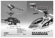
<strong>WINDSTAR</strong> <strong>EP</strong> <strong>MKII</strong><br />
Almost Ready To Fly<br />
2M Electric Powered R/C Sailplane<br />
No.4304 <strong>WINDSTAR</strong> <strong>EP</strong> <strong>MKII</strong><br />
Wing Span/77.3 (1962mm) Length/44.5 (1130mm) Wing Area/ 574sq.in.(37dm 2 )<br />
Weight/52~55oz.(1450-1500g) Wing Loading/13-13.8oz./sq.ft.(38~41 g/dm 2 ) Radio/3 Channel<br />
Warranty:This kit is guaranteed to be free from defects in material and workmanship at the date of<br />
purchase. It does not cover any damage caused by use or modification. The warranty does not extend<br />
beyond the product itself and is limited only to the original cost of the kit. By the act of building this userassembled<br />
kit, the user accepts all resulting liability for damage caused by the final product. If the buyer<br />
is not prepared to accept this liability, it can be returned new and unused to the place of purchase for a<br />
refund.<br />
Notice: Adult Supervision Required:This is not a toy. Assembly and flying of this<br />
product requires adult supervision. Read through this book completely and become familiar with the<br />
assembly and flight of this airplane. Inspect all parts for completeness and damage. If you encounter<br />
any problems, call 660-584-6724 for help.<br />
JE6227
?<br />
?<br />
?<br />
?<br />
?<br />
?<br />
?<br />
?<br />
?<br />
?<br />
?<br />
?<br />
?<br />
?<br />
?<br />
?<br />
?<br />
?<br />
?<br />
?<br />
?<br />
?<br />
?<br />
?<br />
?<br />
?<br />
?<br />
?<br />
?<br />
?<br />
?<br />
?<br />
Windstar <strong>EP</strong> <strong>MKII</strong><br />
ASSEMBLY INSTRUCTION<br />
Table of Contents<br />
Introduction<br />
Pre-Assembly Notes...............................1<br />
Other Items Required.............................1<br />
Tools and Supplies Needed ...................1<br />
Part Drawings........................................2<br />
Assembly<br />
Wing.......................................................3<br />
Fuselage................................................4<br />
Install Control Surfaces.........................9<br />
Install Pushrod....................................10<br />
Install The Radio System....................11<br />
Final Assembly<br />
Control Surface Throws......................12<br />
Mount The Wing.................................12<br />
Balancing Your Windstar <strong>EP</strong> <strong>MKII</strong>......13<br />
First Flights<br />
Checks You Should Make...................13<br />
Flying Your Windstar <strong>EP</strong> <strong>MKII</strong>............13<br />
Safety Precautions..............................14<br />
Following Suggestions.......................14<br />
Congratulations...................................14<br />
INTRODUCTION<br />
All of us at Thunder Tiger want to thank you for choosing the Windstar <strong>EP</strong> <strong>MKII</strong>.This Kit has been engineered to go<br />
together quickly and easily while still providing you with great looks and exceptional flying performance. The world of<br />
electric powered sailplanes can be an extremely challenging and rewarding experience. Your skill along with the<br />
design capabilities of your model will combine to defy the laws of gravity and produce flights of unbelievable distance<br />
or duration. Under proper conditions your Windstar <strong>EP</strong> <strong>MKII</strong> can stay aloft for hours from a single battery charge! As<br />
you gain experience with your model you will be able to<br />
?<br />
W.eW.hg?<br />
?W.Y?W.Yhg?<br />
?7U??7U?hg?<br />
?@1??@1?hg?<br />
?@@??@@?hg?<br />
?<br />
?<br />
?<br />
?<br />
?<br />
?<br />
?<br />
?<br />
?<br />
?<br />
?<br />
?<br />
?<br />
?<br />
?<br />
?<br />
feel<br />
?<br />
@@e@@hg?<br />
3@e3@hg?<br />
S5eS5hg?<br />
?W.Y?W.Yhg?<br />
?.Y??.Y?hg?<br />
?<br />
?<br />
?<br />
?<br />
?<br />
?<br />
?<br />
?<br />
?<br />
?<br />
?<br />
?<br />
?<br />
?<br />
?<br />
?<br />
the wing and lift conditions that affect it enabling<br />
you to greatly extend your flight times.<br />
The Windstar <strong>EP</strong> <strong>MKII</strong> is an electric powered 2-meter sailplane which is intended for use in light to medium wind<br />
and lift conditions. Its airfoil, motor package and design planform are intended to maximize performance under those<br />
flying conditions and will provide great results for pilots of all skill levels.<br />
We suggest that before beginning to assemble this kit you thoroughly read this assembly instruction manual to<br />
familiarize yourself with the complete assembly procedure. This will insure that your assembly process will be as<br />
smooth and uneventful as possible.<br />
We are confident that you will enjoy flying your Windstar <strong>EP</strong> <strong>MKII</strong> and that it will provide many hours of challenging<br />
and rewarding flight.
W2@??W2@<br />
?W&@H?W&@H<br />
?&@@e&@@?<br />
@@@??@@@<br />
?J@@@?J@@@<br />
?@@@@?@@@@<br />
ASSEMBLY INSTRUCTION<br />
Windstar <strong>EP</strong> <strong>MKII</strong><br />
PRE-ASSEMBLY NOTES<br />
1. If you are not an experienced R/C pilot plan to have a fully<br />
competent pilot help you to learn to fly your Windstar <strong>EP</strong><br />
<strong>MKII</strong>. This will help you to be successful much faster and<br />
also avoid potential damage to your model.<br />
2. Please assemble your model exactly according to these<br />
instructions. Do not attempt to modify or change the<br />
Windstar <strong>EP</strong> <strong>MKII</strong> in any way as doing so may adversely<br />
change its flying characteristics.<br />
3. Before you begin please check the entire contents of this<br />
kit against the parts list and part drawings to be sure that no<br />
parts are missing or damaged. This will also help you to<br />
become familiar with each component of your Windstar <strong>EP</strong><br />
<strong>MKII</strong>. If you find that any of the parts are either missing or<br />
damaged please contact your dealer immediately for<br />
replacement. Note: Your dealer cannot accept kits for return<br />
if construction has begun.<br />
For customers in the US and Canada please call or write to<br />
ACE Hobby Distributors, Inc for replacement of missing or<br />
damaged parts.<br />
ACE Hobby Distributors, Inc.<br />
116W 19th St, Higginsville, MO 64037<br />
Tel: 660-584-6704<br />
Fax: 660-584-7766<br />
E-Mail: service@acehobby.com<br />
Remember. We have worked very hard to make this model<br />
as easy to assemble as possible while still maintaining our<br />
high standards of quality. Your assembly of this model is very<br />
important and will determine the final flight capabilities of<br />
your Windstar <strong>EP</strong> <strong>MKII</strong>, so use extra care and follow the<br />
assembly procedure exactly.<br />
OTHER ITEMS REQUIRED<br />
Radio: You will need at least a 3 channel radio control<br />
system with 2 servos on an aircraft frequency for use in your<br />
Windstar <strong>EP</strong> <strong>MKII</strong>. A standard size system will work fine and<br />
fit easily into your model. However, if you are really looking<br />
for every bit of extra performance then you should consider<br />
using one of the miniature radio systems available which<br />
would lower the weight and increase the performance of<br />
your Windstar <strong>EP</strong> <strong>MKII</strong>.<br />
Electronic motor controller: We recommend the ACE<br />
#8007 AUTO CUT-OFF DEVICE with BEC for controlling the<br />
power of your Windstar <strong>EP</strong> <strong>MKII</strong> as well as eliminating the<br />
need for a separate radio battery. The BEC (Battery<br />
Eliminator Circuitry) in this controller will automatically turn<br />
off the power to the motor when the battery reaches a<br />
1<br />
factory present discharge level leaving about 20-25 minutes<br />
of flight time for the radio system. Note: Some radio<br />
manufacturers offer a lightweight radio system with a built-in<br />
motor controller with BEC especially for this type of model.<br />
Flight Battery: We recommend the use of a 7 cell 8.4V<br />
1000 mAh SCR battery pack for maximum performance. A 6<br />
cell 7.2V or 7 cell 8.4V 1200 to 1700 mAh SCR battery will<br />
also work well but will not provide the climb performance of<br />
the 7 Cell 1000mAh SCR pack.<br />
Charger: You will need a quick charger to charge your<br />
power battery. We recommend our #2685 DC Quick Charger<br />
for 6 cell battery or our #2686 DC Quick Charger for 7 cell<br />
battery packs. Note: When charging your flight battery be<br />
sure to very carefully follow the instructions provided with the<br />
charger.<br />
Lead for Balancing: You may need some lead for balancing<br />
your Windstar <strong>EP</strong> <strong>MKII</strong> after you have completed the<br />
installation of your radio and battery. We recommend using<br />
the stick-on type of weights for ease of installation.<br />
#64 Rubber Bands: You will need a minimum of 8 #64<br />
rubber bands for holding the wing firmly on your model.<br />
Foam Rubber Padding: We recommend 1/4 inch thick foam<br />
rubber for use around the receiver to give protection from<br />
vibration and hard landings.<br />
TOOLS AND SUPPLIES NEEDED<br />
1. 5 Minute Epoxy<br />
2. Thin CA Glue<br />
3. Medium CA Glue<br />
4. 1/2 Masking Tape<br />
5. Mixing Stick for Epoxy<br />
6. Medium Grit Sandpaper<br />
7. Rubbing Alcohol<br />
8. Paper Towels<br />
9. Hobby Knife<br />
10. 1/16 Drill<br />
11. 1/8 Drill<br />
12. Light Viscosity Oil<br />
13. Small 90-Degree Triangle<br />
14. Waxed Paper<br />
15. Ruler<br />
16. Z Bend Pliers<br />
17. Pen or Pencil<br />
18. Small Screw Drivers<br />
19. Curved scissors
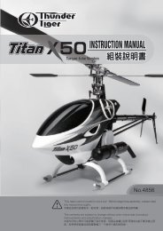
open the box and check that you have all the parts as<br />
shown below. if anything is missing please contact your<br />
AS6078 Fuselage Set Bag<br />
Fuselage (1)<br />
Skid (1) Front Former (1)<br />
Wing Dowel (2) Plywood (2) Brass Hook (1)<br />
AS6076 Wing Bag<br />
Outer Wing Joiner (6)<br />
Tape (6)<br />
Inner Wing Panel(Left/1)<br />
Inner Wing Panel(Right/1)<br />
Inner Wing Joiner (2)<br />
ABS Plastic Plate (1)<br />
Inner Wing Joiner (1)<br />
(Aluminum)<br />
Outer Wing Panel(Left/1)<br />
Outer Wing Panel(Right/1)<br />
AS6077 Tail Set Bag<br />
PE0012 Canopy Set Bag<br />
PE0013 Cowl Bag<br />
Vertical Tail (1)<br />
Fin/Rudder<br />
Canopy (1)<br />
Balsa Wood (1)<br />
Conopy Frame (1)<br />
Cowling (1)<br />
M2.6x4mm<br />
Self-Tapping<br />
Screw (4)<br />
PE0011 Hardware Set Bag<br />
Horizontal Tail (1)<br />
Stabilizer/Elevator<br />
Horn Back Plate (2)<br />
Control Horn Screw (4) Control Horn (2)<br />
Locked Hinges (7)<br />
Rubber Band (1)<br />
PE0565 Propeller Set Bag<br />
HMF2-8N Screw (1) Washer (1)<br />
Drive Nut (1)<br />
Propeller Fin (1) Spinner Cap (1) Spinner Backplate (1)<br />
HMF2-8N Screw (1)<br />
HMF2-12 Screw (2)<br />
AS0252 Motor Set Bag<br />
PE0566 Motor Mount Set Bag<br />
AS1084 Push Rod Set Bag<br />
Motor Mount (Left/1)<br />
Motor Mount (Right/1)<br />
Push Rods (2)<br />
M3x8mm Screw (2)<br />
M3x8mm<br />
Self-Tapping Screw (4)<br />
Clevis (2)<br />
2
ASSEMBLY / WING<br />
Windstar <strong>EP</strong> <strong>MKII</strong><br />
ASSEMBLY<br />
Wing<br />
5. After the epoxy has dried remove the tape from all<br />
three joiner assemblies and sand the edges of each<br />
to remove any excess epoxy.<br />
1.Open the small wood parts bag and remove the wing<br />
panel joiner sets. You will find two sets (3 plywood<br />
pieces each) of outer wing joiners and one set (2<br />
plywood pieces and 1 aluminum piece) of wing<br />
center section joiners. Note: The outer joiner<br />
pieces have a greater dihedral angle cut into them<br />
than the inner joiner pieces.<br />
2.Sand the edges of each plywood joiner piece to<br />
remove any high spots or rough edges.<br />
6. Select the left inner wing panel and the left outer<br />
wing panel and place on your work table. Trial fit on<br />
of the outer wing joiners into the joiner box. The<br />
joiner assembly should fit easily into the joiner box<br />
on both sides. If the joiner is too snug sand<br />
adequately to provide a good fit. Note: It is<br />
necessary for the joiner to bend slightly as the two<br />
panels come together to allow the end ribs to meet<br />
flush. Now repeat this fitting process on the right<br />
inner and outer wing panels.<br />
3. Using 5-minute epoxy assembly the two outer wing<br />
joiners. Apply a thin coat of epoxy to each side of<br />
one of the plywood pieces for each joiner and<br />
sandwich that piece between the other two plywood<br />
pieces. Press this assembly firmly together using<br />
care to keep the pieces aligned end wrap tightly<br />
with 1/2 masking tape to hold until dry.<br />
4. Assemble the wing center section joiner using 5-<br />
minute epoxy. Sand both sides of the aluminum<br />
joiner piece to insure a good glue bond. Apply a<br />
thin coat of epoxy to both sides of the aluminum<br />
joiner and sandwich it between the two plywood<br />
pieces. Press this assembly firmly together using<br />
care to keep the pieces aligned and wrap tightly<br />
with 1/2 masking tape to hold until dry.<br />
7. Now trial fit two inner wing panels together using<br />
the center wing joiner with the aluminum center. Be<br />
sure that the two panels line up at center joint.<br />
Note:”L” means left inner wing pannel, “R” means right<br />
inner wing pannel.<br />
8. Join the inner wing panels at the center. Mix up an<br />
ample amount of 5-minute epoxy (use 15 minute<br />
epoxy if you do not work fast) to install the center<br />
joiner in both panels and to coat the center wing rib<br />
face. Coat one end (halfway) of the center wing<br />
joiner with a thick coat of epoxy, spread epoxy<br />
3
ASSEMBLY / FUSELAGE<br />
inside the joiner box on one wing panel and insert<br />
the coated end of the joiner into the joiner box.<br />
Now coat the entire exposed area of the center<br />
joiner, spread epoxy into the joiner box on the other<br />
wing panel, coat the center rib face of one panel<br />
and push the entire assembly together inserting the<br />
joiner into the joiner box. Push the panels together<br />
tightly and be sure they line up properly at the<br />
center. Wipe off excess epoxy that has oozed out of<br />
the joint with rubbing alcohol. Hold the assembly<br />
tightly together while the glue dries with 1/2<br />
masking tape across the joint in 4 places (2 top and<br />
2 bottom)<br />
11.Join the right outboard wing panel to the wing<br />
assembly. Repeat the step 10 process for the right<br />
wing panel.<br />
9. After the wing center has dried remove the masking<br />
tape and iron the white trim tape (supplied) to the<br />
center joint on both side.<br />
12.After the epoxy has fully hardened remove the<br />
masking tape you used to hold the panels together<br />
while drying and iron the trim tape to the joints.<br />
10.Next join the left outboard wing panel to the wing<br />
center section assembly. Mix enough epoxy to<br />
cover the entire wing joiner and the face of the<br />
joining rib. Spread epoxy inside the appropriate<br />
wing joiner boxes in the outer wing panel and the<br />
enter section assembly, coat the entire wing joiner<br />
and the face of one rib at the joint. Insert the joiner<br />
into the outer wing panel joiner box and slide this<br />
assembly into the center wing panel assembly.<br />
Push the panels tightly together and be sure that<br />
the line up properly at the joint. Wipe off the excess<br />
epoxy that has oozed out of the joint with rubbing<br />
alcohol. Hold the assembly together while the glue<br />
dries with 1/2 masking tape across the joint in<br />
four places as was done with the center section.<br />
4<br />
13.Locate the 5/16 x 3-3/4 plastic wing protector<br />
from the small parts bag and mark the center with a<br />
light pencil line. Now lightly sand the back side of<br />
this protector to allow glue to sick well. Trail fit this<br />
protector to the top of the wing, flush with the<br />
trailing edge, with the center mark you made<br />
aligned over the center section wing joint. If all<br />
looks well, glue in place with thin CA glue.<br />
Fuselage<br />
1. Locate the stabilizer / elevator assembly and place<br />
it into the stab saddle. You will be able to see the<br />
pre-cut notch in the stabilizer center section through<br />
the covering. Carefully cut the covering film from
ASSEMBLY/FUSELAGE<br />
Windstar <strong>EP</strong> <strong>MKII</strong><br />
the stabilizer to expose the fin slot. Follow the edge<br />
of the slot with a hobby knife being careful not to cut<br />
into the balsa structure. Remove this film on the<br />
both the top and bottom of the stabilizer. Repeat<br />
the same process on the fuselage fin slot.<br />
remove the covering film to expose the balsa wood<br />
surface. Note: Be extremely careful to cut only<br />
through the covering and not into the balsa wood as<br />
doing so will greatly reduce the strength of the<br />
stabilizer and may cause it to fail in fight.<br />
2. Using a 90 degree triangle align one edge of the<br />
triangle with the trailing edge of the stabilizer in<br />
such a position that the other edge of the 90 degree<br />
angle extends through the exact center of the slot in<br />
the stabilizer. Now mark the trailing edge of<br />
stabilizer at the center line you have just<br />
established. Note: This is very important step in the<br />
alignment of your Windstar <strong>EP</strong> <strong>MKII</strong>.<br />
5. Put the stabilizer on the fuselage stab saddle and<br />
insert the fin into the fin slot, be sure to push the fin<br />
all the way down into the slot. Now mark the edges<br />
of the fin on the fuselage and along the edge of the<br />
fuselage and stabilizer onto the fin as shown.<br />
3. Lay the stabilizer in place on the fuselage stab<br />
saddle and align the leading edge slot with the fin<br />
slot in the fuselage and align the center line mark<br />
you made on the trailing edge with the center of the<br />
rear of the fuselage. Now draw a line along the<br />
edge of the fuselage onto the bottom of the<br />
stabilizer as shown.<br />
6. Carefully cut out the covering film in the area you just<br />
marked being careful not to cut into the balsa wood.<br />
4. Using a very sharp hobby knife carefully cut the<br />
stabilizer covering along the lines you just make and<br />
5<br />
7. Your fuselage and tail surfaces should now look like<br />
this, and are ready for assembly.
ASSEMBLY / FUSELAGE<br />
13.Cut the covering from over the holes in the<br />
fuselage for the wing dowels and install the dowels<br />
into fuselage.<br />
8. Place the fuselage on a flat surface and weight it<br />
down by using a book or some other heavy object<br />
placed across the wing saddle.<br />
14.Center the dowels in the fuselage with the same<br />
amount of dowel length protruding from each side<br />
of the fuselage and glue in place using thin CA<br />
glue.<br />
9. Put the stabilizer in the stab saddle and line up the<br />
leading edge slot and the trailing edge center line<br />
with the center of the rear of the fuselage. The<br />
stabilizer should sit flat in the stab saddle and the<br />
tips of the stabilizer should be the same distance<br />
off the work surface. Note: If one stabilizer tip is<br />
higher than the other lightly sand the corresponding<br />
side of the stab saddle to lower the stabilizer tip<br />
until both tips are the same height off the table.<br />
10.Using five-minute epoxy (to give time to check<br />
alignment) glue the stabilizer in position on the<br />
stab saddle. Be sure to check center line<br />
alignment and the height of the stab tips off the<br />
table as the glue dries.<br />
15.Locate the two pieces of square cut plywood and<br />
use CA glue to glue two pieces together face to<br />
face.<br />
16.Using a ruler and pencil find the center of the twp<br />
glued pieces by drawing diagonal line from corner<br />
to corner. Then drill a 1/16 hole in the center of<br />
the plywood piece you just marked where your<br />
lines cross.<br />
17.Using the screw end of the brass hook (supplied)<br />
screw the brass hook into the hole in the center of<br />
the plywood piece until the point is just barely<br />
visible through the other side. Now using thin CA<br />
glue apply 2 drops where the brass threads screw<br />
into the plywood to secure the brass hook into the<br />
wood. Be sure the open hook is directly toward<br />
one of the edges of the plywood.<br />
11.Now trial fit the vertical fin into the fin slot to check<br />
for proper fit and alignment. Using the 90-degree<br />
triangle align the fin at exactly 90 degrees to the<br />
stabilizer as shown.<br />
12.While keeping the fin aligned at exactly 90 degrees<br />
to the stabilizer glue the fin in place by applying<br />
thin CA glue along the edge of the fin where it<br />
contacts the fuselage and the stabilizer.<br />
6
ASSEMBLY / FUSELAGE<br />
Windstar <strong>EP</strong> <strong>MKII</strong><br />
18.Use medium CA glue to glue the hook assembly<br />
you just prepare onto the fuselage floor just in front<br />
of the bulkhead with the open side of the brass<br />
hook facing forward.<br />
place by bending the rear former up at the score<br />
lines. Be careful not to break the rear former loose<br />
from the main frame.<br />
23. Now remove the frame and put a small amount of<br />
19.Locate the front canopy former. Trial fit the front<br />
canopy former into the slots in the fuselage which<br />
are just behind the firewall. Sand the former<br />
slightly of necessary to be sure that the tabs on the<br />
edges of the former sit down on top of the fuselage.<br />
20.When satisfied, glue the former in place with thin<br />
5 minute epoxy in the gap you created in the<br />
bottom of the canopy frame at the rear bulkhead<br />
when you bent the frame to fit the fuselage. Now<br />
cover this area with a small piece of waxed paper<br />
and push the frame back into place on the<br />
fuselage.<br />
24.Use masking tape to hold the canopy frame in<br />
CA.<br />
21.Locate the lower canopy frame with attached rear<br />
place till the glue dries. This should lock the rear<br />
canopy former at the correct angle.<br />
25.Refer to the cut lines and place the dried canopy<br />
canopy frame.<br />
22.Place the lower canopy frame and rear former in<br />
frame inside the canopy with the rear top edge of<br />
the rear canopy former located about 1 inch in from<br />
the end of canopy. Now using thin CA securely<br />
glue the canopy frame into the canopy.<br />
26.Trim the canopy flush with the bottom of the canopy<br />
frame base along the cut lines.<br />
7
ASSEMBLY / FUSELAGE<br />
using two 3x8 mm screws provided. Line up the<br />
cooling slots in the motor with the center slots on<br />
each side of the motor holder and tighten the<br />
screws to lock the motor in place.<br />
27.Cut 2 pieces of 1/4 square balsa to fit across<br />
inside the fuselage under the canopy frame for<br />
alignment. One piece should fit approximately 1/3<br />
of the way up the rear former and one just in front<br />
of the front canopy opening of the canopy frame.<br />
Cut these pieces to fit exactly between the<br />
fuselage sides at these locations. Center these<br />
pieces on the canopy frame at the locations<br />
described and glue them in place.<br />
28. Locate the motor pack and propeller set as<br />
shown.<br />
30.Insert the motor wires through the holes in each<br />
side of the firewall and hold the motor assembly in<br />
place against the firewall. Adjust the position of the<br />
assembly on the firewall so that the distance from<br />
the mounting tabs to both the top and bottom of the<br />
firewall is approximately equal and mark the<br />
mounting hole locations.<br />
31.Remove the motor assembly and drill 1/16 pilot<br />
holes(or use an awl) for mounting screws at the<br />
locations you just marked. Now reinstall the motor<br />
assembly and screw firmly in place using the four<br />
mounting screws provided.<br />
29. Assemble the motor holder around the motor<br />
32.Cut the cowl mounting flange away from the cowl<br />
along the cut lines by using curved scissors.<br />
8
?<br />
?<br />
?<br />
?<br />
?<br />
?<br />
?<br />
?<br />
?<br />
?<br />
?<br />
?<br />
?<br />
?<br />
?<br />
?<br />
?<br />
?<br />
?<br />
?<br />
?<br />
?<br />
?<br />
?<br />
?<br />
?<br />
ASSEMBLY / CONTROL SUNFACES<br />
Windstar <strong>EP</strong> <strong>MKII</strong><br />
33.Cut the front opening in the cowl for the motor<br />
shaft. Leave a 1/4 lip around the front opening .<br />
Now carefully cut out the air inlet opening on the<br />
top of the cowl using the molded cut lines to allow<br />
cooling air to enter the cowl.<br />
37.Install the prop blades onto the backplate hub with<br />
the screws provided. Install the motor shaft spindle<br />
and mount the prop and spinner.<br />
34.Put the canopy in place on the fuselage and<br />
temporarily tape in place using 4 pieces of tape.<br />
Now slide the cowl in place over the motor and<br />
temporarily install the motor shaft spindle, propeller<br />
backplate,washer , nut and spinner. Center the<br />
nose of the cowl approximately 1/16 behind the<br />
spinner backplate and use 4 pieces of tape from the<br />
cowl onto the spinner to hold this aligment.<br />
38.If necessary trim the mounting flange on the plastic<br />
landing gear skid down to 1/8 all the way around.<br />
With the deepest section of the skid forward<br />
position it on the bottom of the fuselage 1/4<br />
behind the back edge of the cowl and centered on<br />
the fuselage. Glue in place with thin CA by running<br />
a small bead of glue around the edge of the joint<br />
?<br />
?<br />
?<br />
?<br />
?<br />
?<br />
?<br />
?<br />
W.eW.hg?<br />
@@e@@hg?<br />
3@e3@hg?<br />
?W.Y?W.Yhg?<br />
?7U??7U?hg?<br />
S5eS5hg?<br />
?@0Y?@0Yhg?<br />
?@)??@)?hg?<br />
?<br />
?<br />
?<br />
?<br />
?<br />
?<br />
?<br />
?<br />
?<br />
?<br />
?<br />
?<br />
?<br />
?<br />
?<br />
?<br />
?<br />
?<br />
?<br />
?<br />
?<br />
?<br />
and ?<br />
allowing it ?<br />
to wick underneath.<br />
?<br />
?<br />
?<br />
?<br />
?<br />
?<br />
Install control surfaces<br />
1. Find the two nylon control horns and cut them down<br />
as shown using a hobby knife.<br />
35.Put slight downward pressure on the back of the<br />
cowl to fit it snugly down onto the front of the<br />
canopy. This will create a slight opening between<br />
the bottom of the cowl and the fuselage which will<br />
allow cooling air to escape. Now drill 1/16 pilot<br />
holes for the 4 mounting screws through the cowl<br />
and into the fuselage. These holes should be<br />
positioned 1/4 from the top and bottom of the<br />
fuselage side and 1/4 from the back of the cowl.<br />
We recommend that you drill the two holes on one<br />
side of the fuselage and insert the cowl mounting<br />
screws before moving to the second side, this will<br />
help maintain proper cowl aligment.<br />
36.With the cowl and screws installed remove the tape<br />
from the canopy and the spinner and check the<br />
final aligment of the cowl and spinner.<br />
9<br />
2. Remove the rudder from the fin and lay it on the<br />
work surface with the left side facing up. Position<br />
one control horn on the rudder as shown with the<br />
edge of the base of the control horn parallel to and<br />
approximately 1/8 up from the bottom of the<br />
rudder. The upper front edge of the horn base<br />
should be approximately 1/8 back from the
ASSEMBLY / PUSHROD<br />
rudder hinge line. Now using the horn as a<br />
template mark the location of the mounting screws<br />
holes.<br />
3. With the elevator in position on the stabilizer place<br />
the other control horn on the bottom of the elevator<br />
with the front of the base 1/8 back from the<br />
leading edge of the elevator and the horn centered<br />
in front of the rear fuselage opening. Mark the<br />
location of the horn mounting holes.<br />
7. Install the hinges in the elevator using the process<br />
described in steps 5 above.<br />
8. As soon as the epoxy has dried from step 7 work<br />
the hinges to be sure they move freely and then<br />
install the elevator to the stabilizer by again gluing<br />
hinges as describe above.<br />
4. Drill the mounting holes with a 1/6 bit and install<br />
the horn on both elevator and rudder by using the<br />
mounting screws and nylon nut plate.<br />
9. Using your hobby knife cut the covering away from<br />
the opening at the rear of the fuselage for the<br />
elevator pushrod exit.<br />
5.Using 5-minute epoxy glue the hinges into the<br />
rudder. Use an old knife blade or similar item to put<br />
glue inside the slot cut for the hinges and apply a<br />
very small amount of glue on the contact. Area of<br />
the hinge being installed. Push the hinge into the<br />
slot and wipe any excess glue away from the hinge.<br />
Note: It is important not to get glue into the hinge<br />
pin area or it may glue the hinge solid. Hint : apply a<br />
very small amount of thin oil directly on the hinge<br />
pin area of each hinge before installation and do not<br />
move the hinge back and forth until after the glue<br />
has dried. This will keep any excess glue from<br />
getting inside the hinging area and allow you to pop<br />
any excess glue off the joint by working the hinge<br />
back and forth after glue has dried.<br />
6. Install the rudder onto the fin by using the same<br />
process of gluing the hinges as in the same process<br />
of gluing the hinges as in the previous step. Note : It<br />
is important to keep the hinge gap (distance<br />
between the fin and rudder) as small as possible.<br />
Install Pushrod<br />
1. Locate the two pre-assembled pushrods and apply<br />
4 to 5 drops of thin CA glue into each end of both<br />
push rods where the dowel, wire and shrink tubing<br />
meet. This will harden the assembly together and<br />
insure that no flexing will occur during use.<br />
10<br />
2. Using your hobby knife cut the covering away from<br />
the pushrod exit hole for the rubber pushrod in the<br />
left side of the fuselage.
?<br />
?<br />
?<br />
?<br />
?<br />
?<br />
?<br />
?<br />
?<br />
?<br />
?<br />
?<br />
?<br />
?<br />
ASSEMBLY / RADIO<br />
Windstar <strong>EP</strong> <strong>MKII</strong><br />
slight amount of balsa from inside the pushrod<br />
opening at the rear of the fuselage if the clevis is<br />
rubbing.<br />
Install The Radio System<br />
Note: Always follow the mounting suggestion supplied<br />
with your radio system.<br />
3. Use the shorter of the two pushrods and insert the<br />
threaded end first down the inside of the fuselage,<br />
starting through the radio compartment. and out<br />
through the rudder pushrod exit hole.<br />
4. Screw one of the clevis onto the threaded pushrod<br />
until approx. 1/4 of thread is visible inside the<br />
clevis.<br />
5. Attach the clevis to the control horn in the center<br />
hole. Note: It may be necessary to bend the<br />
pushrod wire slightly where it exits the fuselage to<br />
allow free movement of the pushrod.<br />
1. Use 1/16 double sided mounting tape to mount<br />
the Auto Cut-off Device to the bottom of the<br />
fuselage in the front compartment of the nose. Plug<br />
the motor leads of the Auto Cut-off Device into the<br />
leads from the motor, observing the proper polarity.<br />
2. Mount the on/off switch from the Auto Cut-off<br />
Device just behind the nose section center<br />
bulkhead approximately 1/2 of the way up the<br />
fuselage side. Use the switch plate from the switch<br />
as a guide to accurately mark and cut the hole and<br />
screw locations. Also install the push button of the<br />
Auto Cut-off Device 1/2 before the switch.<br />
6. Install the elevator pushrod down the fuselage the<br />
same way and exit it out the slot in the tail of the<br />
fuselage.<br />
3. Position your servos in place in the servo tray with<br />
the output shafts toward the front of the fuselage.<br />
Use the mounting screws provided with your radio<br />
to mount the servos to the servo tray.<br />
7. Screw the other clevis onto the threaded portion of<br />
?<br />
@@e@@hg?<br />
3@e3@hg?<br />
S5eS5hg?<br />
?@0Y?@0Yhg?<br />
?<br />
?<br />
?<br />
?<br />
?<br />
?<br />
?<br />
?<br />
?<br />
?<br />
?<br />
?<br />
?<br />
?<br />
this pushrod until 1/4 of thread is visible inside the<br />
?<br />
?<br />
?<br />
clevis.<br />
8. Attach this clevis to the bottom hole (farthest from<br />
the elevator) of the elevator clevis.<br />
9. Check the elevator pushrod assembly for freedom<br />
of movement. It may be necessary to remove a<br />
11
FINAL ASSEMBLY / CONTROL SURFACE THROWS<br />
4. Install the receiver in the aft nose compartment as far<br />
forward as possible. Be sure to cushion the bottom and<br />
sides of the receiver with thin foam to protect it.<br />
5. Plug in the components of your radio system according to<br />
the radio and Auto Cut-off Device instructions. Plug in the<br />
servos so the servo on the left side is the elevator and the<br />
servo on the right is rudder.<br />
wing dowel and up to the top of the fin. Attach the<br />
antenna using the antenna keeper supplier with your<br />
radio.<br />
FINAL ASSEMBLY<br />
Control Surface Throws<br />
For first flights on your Windstar <strong>EP</strong> <strong>MKII</strong> we recommend<br />
the following control surface movement.<br />
Rudder 1-1/2 right and 1-1/2 left<br />
Elevator 1/2 up and 1/2 down<br />
6. Place servo arms on your servos. Trim the length of the<br />
arms to be sure that they do not hit the other servo or the<br />
fuse side. Line up the appropriate pushrod wire to the<br />
center of each servo arm in its neutral position. Mark the<br />
wire at the exact hole location in the servo arm where it<br />
W.e?W.?hg<br />
@@e?@@?hg<br />
?W.YeW.Y?hg<br />
3@e?3@?hg<br />
S5e?S5?hg<br />
?7U?e7U<br />
?W.YeW.Y?hg<br />
?@1?e@1<br />
?.Y?e.Y<br />
?@@?e@@<br />
will attach. Now make a Z bend in the wire at this<br />
location and cut off any excess wire which extends more<br />
W.e?W.?hg<br />
@@e?@@?hg<br />
?W.YeW.Y?hg<br />
3@e?3@?hg<br />
?7U?e7U<br />
S5e?S5?hg<br />
?@1?e@1<br />
?W.YeW.Y?hg<br />
?.Y?e.Y<br />
?@@?e@@<br />
than 1/4 past the Z bend.<br />
W.e?W.?hg<br />
@@e?@@?hg<br />
?W.YeW.Y?hg<br />
3@e?3@?hg<br />
?7U?e7U<br />
S5e?S5?hg<br />
?W.YeW.Y?hg<br />
?@1?e@1<br />
?.Y?e.Y<br />
?@@?e@@<br />
7. Thread the Z bends into the servo arms and attach<br />
the servo arms to the servo output shafts.<br />
8. Now turn on the radio and check to see that the control<br />
surfaces are in their neutral position when the servos are<br />
centered. If not adjust the clevis in or out to center the<br />
surface. Also check to be sure the controls move<br />
smoothly and do not bind<br />
Note: The control throw is measured at the point of the<br />
control surface farthest from the hinge line. You can<br />
move the pushrod attach points in or out on the control<br />
horns and servo arms to change the amount of throw on<br />
each surface.<br />
These are the suggested starting throws for your<br />
Windstar <strong>EP</strong> <strong>MKII</strong> and later you may wish to change<br />
them to fine tune the handing to your own personal<br />
preference.<br />
Mount The Wing<br />
9. Drill a small hole in the side of the fuselage near the<br />
receiver for the receiver antenna to exit the fuselage.<br />
Thread the antenna through this hole, Under the rear<br />
12<br />
We recommend that you always use eight #64 rubber bands to hold<br />
the wing of your Windstar <strong>EP</strong> <strong>MKII</strong> onto the fuselage. During flight the<br />
stresses on the wing are sometimes very great and tend to try to lift<br />
the wing off of the fuselage if it is not adequately attached.
W-X?<br />
*@1?<br />
V'@?<br />
?S5?<br />
?.Y?<br />
FINAL ASSEMBLY / BALANCING<br />
Windstar <strong>EP</strong> <strong>MKII</strong><br />
Balancing Your <strong>WINDSTAR</strong> <strong>EP</strong> <strong>MKII</strong><br />
the help of an experienced modeler for your first few flights. He can<br />
save you a lot time and possible disappointment by helping you get<br />
your model in the air safely and getting it trimmed out for you.<br />
Balancing your model is very important and must not be<br />
overlooked. The center of gravity (CG) of your Windstar <strong>EP</strong><br />
<strong>MKII</strong> should be 2-1/2 behind the leading edge of the wing.<br />
Add lead weight to the nose compartment of your model just<br />
behind the firewall until the correct balance point is reached.<br />
To check the balance the model must be fully assembled<br />
with flight battery installed and ready to fly. Make a mark on<br />
the bottom of the wing 2-1/2 back from the leading edge<br />
on both sides of the fuselage. Pick up the plane from a level<br />
position using on finger under the wing on each mark. Add<br />
lead until the plane remains level when you pick it up. After<br />
you have become familiar with your model’s performance<br />
you may wish to change the CG slightly to change how<br />
@@e?@@?hg<br />
W.e?W.?hg<br />
?W.YeW.Y?hg<br />
3@e?3@?hg<br />
?7U?e7U<br />
S5e?S5?hg<br />
?W.YeW.Y?hg<br />
?@1?e@1<br />
?.Y?e.Y<br />
?@@?e@@<br />
responsive your model feels to the controls. Caution:<br />
Do not move the CG more than 1/2 in either direction.<br />
FIRST FLIGHTS<br />
Checks You Should Make<br />
Before you attempt to fly your model you should perform some final<br />
checks:<br />
1. Fully charge your radio and flight batteries following the<br />
manufacturers instructions.<br />
2.Check the direction of travel of your control surfaces and the<br />
operation of the motor controller per the manufacturers<br />
instructions.<br />
3.Range check your radio system per the manufacturers<br />
instructions.<br />
4. Double check that you have installed the screws in the servo<br />
control arms and that the clevis are snapped tightly on the<br />
control horns.<br />
We strongly recommend that you get help from an experienced R/C<br />
pilot to learn to fly if you are just beginning. You should be able to<br />
find help at your local dealer or club field.<br />
Flying Your <strong>WINDSTAR</strong> <strong>EP</strong> <strong>MKII</strong><br />
First of all, if you are flying with other flyers, check to make sure<br />
they are not operating on the same frequency as you. If they are,<br />
do not turn on your radio until they have safely landed and have<br />
turned their radios off.<br />
Secondly, even though the Windstar <strong>EP</strong> <strong>MKII</strong> is very easy to fly, if<br />
you are a novice modeler/pilot, we highly recommend that you seek<br />
13<br />
Important: The radio control system is set up to operate the<br />
control surfaces just like a real airplanes as if the pilot (you) are<br />
sitting in cockpit controlling the airplane. When you want the plane<br />
to dive, you push the elevator stick forward (up), to climb you pull<br />
the stick back (down), to turn right, you move the rudder stick to<br />
right and visa versa. When you want to turn the motor on you push<br />
the throttle stick forward and when you want to turn the motor off<br />
you pull the stick back. It is the turning that causes the most<br />
problems with novice pilots because when the plane is flying<br />
towards you a right turn command on the transmitter cause the<br />
plane to turn to your left (which is the planes right). Get the<br />
picture? Fortunately the up and down commands do not change.<br />
The easiest way to conquer this problem is to try and always face<br />
your body near the direction the planes is flying. This means that<br />
you will have to look over your shoulder at times, but many<br />
modelers find this an easy way to learn.<br />
THE FIRST FLIGHTS<br />
You should always use the first few flights to get accustomed to<br />
your new airplane and its flying characteristics. Keep the model<br />
upwind and climb to a good comfortable altitude to cut off the motor<br />
and trim your Windstar <strong>EP</strong> <strong>MKII</strong> for a glide. At altitude cut the<br />
motor and start your glide. Have an experienced modeler adjust<br />
the trims of the transmitter for you until the plane will glide straight<br />
and level without any other control input. Once the trims are set<br />
practice making smooth turns in both directions while losing as little<br />
altitude as possible. When the Windstar <strong>EP</strong> <strong>MKII</strong> starts to get too<br />
low for comfort turn the motor back on and climb back up to altitude.<br />
Practice this climbing and gliding until you are comfortable with the<br />
airplane.<br />
Depending on the battery you use the Windstar <strong>EP</strong> <strong>MKII</strong> will make<br />
2 to 3 good climbs up to a nice thermal searching altitude from<br />
single battery charge. Once the Auto Cut-off Device shuts off the<br />
power to the motor you will need to set up for your landing.<br />
Continue to make smooth gently turns while lining up the Windstar<br />
<strong>EP</strong> <strong>MKII</strong> with your landing strip. Once you are set up to land keep<br />
the wings level and let the model settle in for an nice gentle landing<br />
while adding up elevator to keep the nose up slightly as the plane<br />
slows down. Make several flights like this to really familiarize<br />
yourself with the characteristics of your model and to learn the glide<br />
and distance covering abilities of the Windstar <strong>EP</strong> <strong>MKII</strong>. Once you<br />
W.e?W.?hg<br />
@@e?@@?hg<br />
?W.YeW.Y?hg<br />
3@e?3@?hg<br />
?7U?e7U<br />
S5e?S5?hg<br />
?@1?e@1<br />
?W.YeW.Y?hg<br />
?.Y?e.Y<br />
?@@?e@@<br />
have mastered a good comfort level you are ready to start<br />
searching for thermals which will really increase your flight times.<br />
THERMALS<br />
Thermal soaring is one of the most interesting and challenging<br />
types of flying there is. Believe it or not, your Windstar <strong>EP</strong> <strong>MKII</strong> is<br />
capable of flights thousands of feet high, lasting for several hours,<br />
and covering dozens of miles. The following paragraphs will help<br />
explain how to take advantage of natures energy sources called<br />
thermals.<br />
W.e?W.?hg<br />
?W.YeW.Y?hg<br />
?7U?e7U<br />
?@1?e@1<br />
?@@?e@@<br />
Thermal<br />
@@e?@@?hg<br />
3@e?3@?hg<br />
S5e?S5?hg<br />
?W.YeW.Y?hg<br />
?.Y?e.Y<br />
is the term applied to columns of rising air. This air is<br />
rising because it is warmer than the surrounding air. A dust devil is<br />
simply a thermal which ahs picked up some dust. Even a tornado<br />
is very similar to a thermal, but of course much stronger.<br />
Thermals occur when the sun, or other heat source, heat the air in<br />
one location faster and/or warmer than the surrounding air. Darker<br />
surfaces (plowed fields, asphalt parking lots, etc.) absorb the sun
SAFETY PRECAUTIONS<br />
s energy faster than lighter colored and are generally good thermal<br />
generators. This warmer air is lighter (less dense) than the cooler<br />
air and thus rises. The rising air naturally starts to rotate, much like<br />
water going down a drain, and forms an inverted funnel shaped<br />
column that usually gets larger with altitude. This warmer air often<br />
contains water vapor which condenses as it reaches the cooler air<br />
high above the earth forming big puffy Cumulus clouds that<br />
experienced sailplane flyers will watch to determine where the<br />
thermals are forming. Thermals vary in strength, but often contain<br />
air that is rising at speeds over 1200 feet per minute. Some<br />
thermals are so strong they can even rip a sailplane apart,<br />
especially if the plane is flying fast when it passes through the<br />
thermal.<br />
THERMAL SOARING<br />
It takes lots of practice and concentration to thermal soar like the<br />
Hawks and Eagles. Since the pilot is not sitting inside an model<br />
sailplane, he cannot feel the thermal, he can only see his sailplanes<br />
reaction to the thermal. Therefore, the majority of the time, unless<br />
the pilot is paying careful attention to the plane, he may not even<br />
realize that plane is near a thermal. Since most thermals are<br />
relatively small, less than a hundred feet in diameter near the<br />
ground, the sailplane will rarely fly directly into the thermal and start<br />
rising. More likely, it will fly near a thermal and the wing closest to<br />
the thermal will rise turning the plane away from the thermal. So as<br />
you can see, an inexperienced pilot may bounce around between<br />
the thermals with ever knowing that he is encountering rising air.<br />
In order to take advantage of thermals, you need to fly smoothly with<br />
as few control inputs as possible. Watch the sailplane carefully and<br />
it will tell you what the air around it is doing.<br />
When a sailplane does fly directly into a thermal it will either start<br />
rising or stop sinking at its normal rate. Either case is reason<br />
enough to explore further. Continue flying straight ahead until you<br />
have obviously passed through the area of strongest lift. Now start<br />
circling in fairly tight, but smooth circles. Because of the thermals<br />
inverted funnel shape, the lower the planes altitude, the tighter the<br />
circles need to be. As the plane gains altitude, the diameter of the<br />
circles can be increased. If you see the plane falling off on one side<br />
of the turn, move the circle over into the stronger lift. Thermals are<br />
swept along by the wind so allow your circle to drift downwind with<br />
the thermal. Be careful when following a thermal downwind though<br />
as you still have to be able to make it back to the field!<br />
As you might expect, with all this rising air, there must also be some<br />
sinking air. This sinking air is the sailplane pilots enemy and one of<br />
@@e?@@?hg<br />
W.e?W.?hg<br />
3@e?3@?hg<br />
?W.YeW.Y?hg<br />
S5e?S5?hg<br />
?7U?e7U<br />
?@1?e@1<br />
?W.YeW.Y?hg<br />
?@@?e@@<br />
?.Y?e.Y<br />
the factors that really make soaring challenging. Sink as it is<br />
referred to, is usually not as strong as the nearby thermals, but is<br />
can quickly put a sailplane on the ground. Sink in one of the<br />
reasons, you have to be very careful when chasing a thermal<br />
downwind. If you encounter sink, immediately turn and fly 90<br />
degrees to the direction of the wind. Apply a little down elevator to<br />
pick up some speed and get out of the bad air as quickly as<br />
possible.<br />
Safety Precautions<br />
You as the pilot of this radio controlled model are responsible for any<br />
accidents that may occur during its use. We recommend that you fly<br />
your model at a model club field which is specially set up for model<br />
flying. But always be sure that you operate the model in a safe and<br />
careful manner and observe the<br />
Following Suggestions:<br />
1. Do not fly your model close to buildings, power lines, roads, or<br />
other obstacles.<br />
2. Do not fly in congested areas such as parks or occupied playing<br />
fields. Select wide, flat and open area to fly with no obstructions<br />
and plenty of room for learning to fly.<br />
3. Do not fly without help from an experienced model pilot until you<br />
have learned how to fly. Your local model club or hobby shop<br />
can recommend an instructor if you do not already know one.<br />
4. Always check for other modelers in the area and be sure that your<br />
frequency is not in use by someone else which might cause you<br />
model to crash. Always observe frequency control systems at<br />
flying fields and wait your turn to fly.<br />
5. Never fly your model directly toward spectators, autos, other<br />
modelers or their models.<br />
6. Always abide by the rules for model flying provided by your club<br />
and the governing agency for model aircraft in your country.<br />
Congratulations<br />
If the sailplane is flying along and all of a sudden turns by itself, it<br />
has probably flown near a thermal. Keep in mind that thermal will<br />
have tendency to turn the plane away, so make a 180 degree turn<br />
and fly back towards the thermal. If you don’t quickly encounter lift<br />
start searching around that area. If you find the thermal, follow the<br />
procedure outlined above to take advantage of it.<br />
Thermals can be generated at any time of the day, but the strangest<br />
thermals are usually produced when the sun is directly overhead<br />
10:00am to 2:00pm seems to be the best time to find the strongest<br />
thermals.<br />
If you find yourself getting too high or you’re having trouble getting<br />
out of a strong thermal. DO NOT dive the plane to lose altitude.<br />
This will very quickly over-stress the airframe and blow the wings off<br />
the plane. The easiest and safest way to quickly lose altitude is to<br />
apply full rudder (either right or left) and full up elevator. This will put<br />
the plane into a tight spin that will normally not over-stress the<br />
airframe. This is especially useful if the sailplane gets sucked into a<br />
cloud or gets too high to see. The spinning action will give the sun a<br />
better chance of reflecting off of the wing and catching your attention.<br />
14<br />
Now that you have completed the assembly of your Windstar <strong>EP</strong><br />
<strong>MKII</strong> model we feel that have a very capable and good looking 2-<br />
meter electric sailplane. We hope that you will enjoy this model and<br />
get many hours of flying pleasure from its use. Thank you for<br />
purchasing this Windstar <strong>EP</strong> <strong>MKII</strong> from Thunder Tiger and we look<br />
forward to providing you with other great R/C products in the future.