
Create successful ePaper yourself
Turn your PDF publications into a flip-book with our unique Google optimized e-Paper software.
POST-FLIGHT CHECK<br />
If you get disoriented or the plane gets out of control,<br />
simply take your hands off all the controls and allow the<br />
plane to stabilize. Clear your head and try to picture<br />
yourself sitting in the cockpit. Then input the required<br />
control movements to get the plane back on the correct<br />
flight path. If you run out of time or flying space and<br />
realize the plane is going to hit something (ground, tree,<br />
etc), pull the throttle back to idle and pull the elevator<br />
stick back about half way. This will reduce the speed of<br />
the plane and minimize the damage sustained.<br />
When you are ready to land, do a coupler of slow fly-bys<br />
at a safe altitude to get familiar with the plane's slowflying<br />
characteristics. An important factor to remember<br />
here is that you should regulate you altitude with the<br />
throttle not the elevator as you might expect. Practice<br />
raising the nose of plane slightly with a touch of “up”<br />
elevator and then using the throttle to regulate the<br />
plane’s altitude. When you are ready to land, fly<br />
downwind past the runway. When the plane is a<br />
hundred yards or so downwind, reduce the throttle<br />
almost an idle and turn 90 degrees towards the runway.<br />
Fly straight for a second or two until the plane is almost<br />
even with the runway. Turn 90 degrees again and fly<br />
directly toward the runway using the throttle to govern<br />
how quickly the plane is descending. Keep the nose of<br />
plane up slightly with the elevator and allow the plane to<br />
fly gently onto the runway. Do not try to stretch the glide<br />
path without increasing the throttle or the plane may<br />
stall.<br />
SAFETY PRECAUTIONS<br />
1.Wear safety glasses when starting and running all<br />
model engines.<br />
2.Model engine fuel is very flammable and the flame is<br />
very dangerous because it is almost invisible! Do not<br />
smoke or allow sparks, high heat or other flames near the<br />
fuel.<br />
3.Do not run model engines inside garage or other closed<br />
room as they give off large amounts of deadly carbon<br />
monoxide gas.<br />
4.Do not run model engines around gravel, sand or other<br />
loose debris. These materials will be ingested through<br />
the carburetor and can also be kicked up by the prop.<br />
5.Always stay behind the propeller when the engine is<br />
running. Make all engine adjustments from behind the<br />
engine. Under no circumstances should you allow your<br />
face or body near the plane on rotation of the propeller<br />
when the engine is running.<br />
6.Do not allow loose clothing or other loose objects close<br />
to the prop.<br />
7.To stop an engine, cut off the fuel or air supply to the<br />
engine. Do not throw rags or other objects into the prop to<br />
stop the engine.<br />
<strong>Assembly</strong> <strong>Instructions</strong><br />
POST-FLIGHT CHECK LIST<br />
1.Be sure that both the transmitter and receiver switches<br />
are turned off.<br />
2.Drain all excess fuel from the tank. Fuel left in the tank<br />
for extended periods can “gunk up” the tank, fittings and<br />
carburetor.<br />
3.Clean the plane with paper towels and a light-duty<br />
spray cleanser. Keeping your plane clean will make it last<br />
longer and keep it looking nice.<br />
4.Put a few drops of after-run or light oil in the carburetor<br />
and turn the prop over a few times (without the glow plug<br />
ignited) to distribute the oil throughout the engine.<br />
5.Inspect the prop and replace it if any chips or cracks<br />
are found.<br />
6.Inspect the entire plane for covering tears, new dings<br />
and dents, loose screws and connect connectors and<br />
any other wear and tear.<br />
7.Use a voltmeter to check the receiver battery voltage.<br />
If it is low, you now know not to fly so long next time. If it<br />
is still high, you should be able to fly a little longer next<br />
session.<br />
8.Do not touch the engine or muffler during or right after it<br />
has been running-It gets very hot!<br />
9.If you hear any unusual noises while your plane is flying,<br />
land at once and determine the problem before returning<br />
to the air. Control surface flutter, which often emits a lowpitched<br />
Buzz, can quickly destroy an airplane and<br />
should not be ignored. Flutter is usually caused by sloppy<br />
control surfaces and is generally relatively easy to cure.<br />
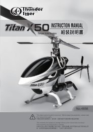
No.4583<br />
Warranty<br />
Thunder Tiger Corp. guarantees this model kit to be free from defects in both material and<br />
workmanship at date of manufacture. This warranty does not cover any components<br />
damaged by use or modification, and in no case shall Thunder Tiger's liability exceed the<br />
original purchase price of the kit. Thunder Tiger also reserves the right to change or<br />
modify this warranty without notice.<br />
Since Thunder Tiger Corp. has no control over possible shipping damages or construction<br />
by the modeler, no liability can be assumed nor accepted for damage resulting from the<br />
use by the user or the final user-assembled product. By the act of using this userassembled<br />
product, the user accepts all resulting liability. If the buyer is not prepared to<br />
accept this liability, he should return this kit in new and unused condition to the place of<br />
purchase for a full refund.<br />
JE6921<br />
16<br />
1
INTRODUCTION<br />
Tiger Trainer MK<br />
ITEMS NEEDED<br />
Introduction<br />
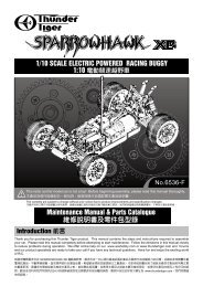
All of us at Thunder Tiger want to thank you for choosing the best looking, easiest<br />
building and best flying ARF trainer available the Tiger Trainer 40.The kit features stateof-the-art<br />
engineering that provides quick and easy assemble of a strong, yet lightweight<br />
airplane that will give you an enjoyable and educational experience.<br />
To gain the most from this airplane kit, it is important that you read the instructions<br />
thoroughly and then follow them exactly. This instruction manual has been written with a<br />
novice modelers in mind, but includes many hints and modeling tips that even<br />
experienced modeler can benefit from. We strongly suggest that you read through the<br />
construction sequence and eliminate many questions you might have if you did not read<br />
the manual prior to starting the actual construction.<br />
The first thing you should do before beginning assembly is to check the contents of your<br />
kit against the parts list on pages 4 and 5. If any parts are missing, contact your dealer or<br />
authorised Thunder Tiger Distributors immediately for replacement.<br />
Adhesives- You will need two types of adhesives for the<br />
Tiger Trainer - Epoxy and Instant ( cyanoacrylate )<br />
adhesives. We recommend that you purchase both 5-<br />
minute and 30-minute epoxy to cut down on assembly<br />
time, but you can get by with only 30-minute epoxy if time<br />
is no important. You will also need a small bottle of both<br />
"Thick" and "Thin" instant adhesive.<br />
Flight Equipment There are several “support” items<br />
that you will need to purchase in order to get your engine<br />
running and your plane in the air. These are listed at the<br />
bottom.<br />
TABLE OF CONTENTS<br />
INTRODUCTION...........................................................................................2<br />
OTHER ITEMS REQUIRED............................................................................2<br />
ITEMS NEED CHECK LIST.............................................................................3<br />
PARTS LIST...............................................................................................4-5<br />
PRE-ASSEMBLE NOTES...............................................................................6<br />
WING.........................................................................................................6-8<br />
FUSELAGE...................................................................................................8<br />
INSTALL THE ENGINE................................................................................8-9<br />
INSTALL FUEL TANK...................................................................................10<br />
TAIL.......................................................................................................10-12<br />
INSTALL THE RADIO..............................................................................12-13<br />
BALANCE & FINAL ASSEMBLY FLIGHT..................................................14-16<br />
Tools-Model assembly can be much easier if the proper<br />
tools are used. Therefore we have included in our<br />
checklist to above, a complete listing of all the tools we<br />
used to assemble our prototype models. As you will<br />
notice, many household tools can be utilized during<br />
construction.<br />
No.9041<br />
Flight Equipment Needed Check List<br />
Foam Rubber Padding for the radio<br />
Stick on Lead Strip for balancing the plane<br />
3 or 4 Props (see engine instructions)<br />
10%-15% Glow Fuel<br />
Fuel Pump or Bulb<br />
Electric Starter or “ Chicken Stick”<br />
Glow starter<br />
Extra Glow Plug(s)<br />
Silicon Tubing<br />
Comprehensive Items Needed Check List<br />
OTHER ITEMS REQUIRED FOR<br />
ASSEMBLY<br />
A checklist is also provided on the next page which<br />
will make shopping for these items easier.<br />
Radio - A 4- channel radio with 4 standard servos is<br />
required. Most lower priced 4-channel radios only<br />
come with three standard servos so you may need to<br />
purchase the fourth servo separately.<br />
ACCESSORIES<br />
No.1263-65<br />
Carry Master-Thunder<br />
Tiger offer a complete<br />
organizer of field<br />
equipment. All you<br />
need is included.<br />
No.2674<br />
12V DC Starter- Provides high<br />
torque starting power to start<br />
your outboard engine.<br />
No.2624<br />
Sealed Battery- 7Ah 12V<br />
Sealed Battery.<br />
No.9800<br />
Engine The Thunder Tiger GP-42 and F-54S are the ideal<br />
engines for this airplane. These quiet running engines are<br />
easy to start, require no special break in periods, are very<br />
easy to maintain and will last for years.<br />
4-Channel Radio with 4 Standard Servos<br />
5-Minute Epoxy (4 ounces or so)<br />
30-Minute Epoxy (4 ounces or so)<br />
“Thin” Instant Adhesive (1/2 ounce)<br />
“Thick” Instant Adhesive (1/2 ounce)<br />
Hobby Knife and Blades<br />
Epoxy Mixing Sticks and/or Brushes<br />
Sandpaper (150 grit)<br />
Masking Tape<br />
Rubbing Alcohol<br />
Paper Towels<br />
Ruler<br />
90 Degree Triangle<br />
Waxed Paper<br />
Fine-Point, Felt-Tip Pen<br />
Misc. Household Tools<br />
Drill and Bits (1/16", 5/64", 3/32")<br />
2<br />
3
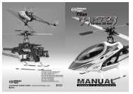
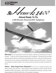
PARTS DRAWINGS<br />
Tiger Trainer MK<br />
PARTS DRAWINGS<br />
AS6548R Fuselage<br />
AS6548L<br />
AS6548Y<br />
Dowel (2)<br />
AS6547 Windshield<br />
2x5mm<br />
Wood Screw (8)<br />
AS6204 Rudd/Elev. Pushrod<br />
Clevis (2)<br />
N40TT<br />
Windshield (1)<br />
Black Window (1)<br />
Pushrod (2)<br />
Fuselage (1)<br />
3102 Adjust Engine Mount PE0009 Hardware Set<br />
AS6549R Main Wing<br />
AS6549L<br />
AS6549Y<br />
3x15mm Screw (4)<br />
6/32x18mmmm Screw (4)<br />
Engine Mount Plate (1)<br />
3x3mm Set Screw (2) Allen Wrench (1)<br />
Tiger<br />
Trainer<br />
Nose Gear Mount (1)<br />
Beams (L/1, R/1)<br />
2mm Hex Nut (2)<br />
2mm Washer (2)<br />
Push Rod<br />
Connector (2)<br />
Left Wing (1) Right Wing (1)<br />
3255 Wheels<br />
3282W Spinner<br />
Trim Tape (1) Aileron Servo Tray (1) Wing Protector (1) Wing Joiner (3) Aileron Torque Horn (2) CA Hinge (8)<br />
Wheel (3)<br />
3x12mm Self<br />
-Tapping Screw (2) Backplate (1)<br />
2" Spinner (1)<br />
3152 Aileron Pushrod<br />
PE0577 Forward Pushrod<br />
AS6203 Landing Gear<br />
3150 Control Horn<br />
Clevis (2) Pushrod (2) Plastic Guide Tube (2) 0.05" Piano Wire (2)<br />
Steering Collar (1) Steering Horn (1) 3x5mm Screw (6)<br />
Nose Gear (1)<br />
2x12mm Screw (4)<br />
AS6550R Tail Feathers<br />
AS6550L<br />
AS6550Y<br />
Tiger<br />
Collar (5) Mounting Strap (2)<br />
3263 Fuel Tank<br />
3x10mmSelf-<br />
Tapping Screw (4)<br />
Main Gear (2)<br />
Cap(1) Rubber Stopper (1)<br />
90-degree Nipple (1)<br />
Nut Plate (2) Control Horn (2)<br />
300cc Fuel Tank (1)<br />
CA Hinge (7) Fin/Rudder (1) Stab./Elevator (1)<br />
Silicone Tube (1) Straight Nipple (1)<br />
Clunk (1)<br />
4<br />
5
PREASSEMBLY<br />
PRE-ASSEMBLY NOTES<br />
1. If you are not an experienced R/C pilot, plan to have a<br />
fully competent pilot check your completed model and<br />
help you with your first flights. Even though we have tried<br />
to provide you with a very thorough instruction manual,<br />
R/C models are rather complicated and an experienced<br />
modeler can quickly check over your model to make sure<br />
your first flights are successful.<br />
Tiger Trainer MK<br />
WING<br />
2. Please assemble your model exactly according to these<br />
instructions. Do not attempt to modify or change the Tiger<br />
Trainer in any way as doing so may adversely change<br />
its flying characteristics.<br />
3. Before you begin, please check the entire contents of<br />
this kit against the parts drawing make sure that no parts<br />
are missing or damaged. This will also help you to<br />
become familiar with each component of your plane. If<br />
you find that any of the parts are either missing or<br />
damaged, please contact your dealer immediately for<br />
replacement.<br />
Note: Your dealer cannot accept kits for return if<br />
construction has begun.<br />
2. Clamp the three joiners together with clothes-pins or<br />
other small clamps and wipe off the excess epoxy before<br />
it cures. Allow the epoxy to cure before removing the<br />
clamps.<br />
5. With 30-minute epoxy, liberally coat all sides and<br />
edge of the wing joiner and slip it into one wing half.<br />
Now coat the inside edge of the center wing rib where it<br />
will join to the other wing half. This is called the “root” of<br />
the wing.<br />
Join the two wing halves and firmly press wing panels<br />
together. Wipe off any excess epoxy with a paper towel<br />
and rubbing alcohol. Make sure the two panels are<br />
accurately aligned with each other. You may hold<br />
together with several strips of masking tape.<br />
4. Trial fit each part before gluing it in place. Make sure<br />
you are using the correct part and that it fits well before<br />
assembling. No amount of glue can make up for a poor<br />
fitting part.<br />
7. Remove the tray, and use a sharp knife to score the<br />
covering material where marked. Remove the covering<br />
material to expose the wood underneath. Use thick CA<br />
or epoxy to glue the servo tray securely in place.<br />
WING ASSEMBLY<br />
3.On the bottom of one wing half, make a mark 3/8''<br />
(10mm) from the inside edge of the wing, between the<br />
pre-cut slot in the center rib and the rear edge of the spar<br />
box. Use a hobby knife to cut away the covering and<br />
balsa sheeting in this area.<br />
6. Place the servo tray centered over the cutout in the<br />
bottom of the wing. Mark around the servo tray with a<br />
pencil.<br />
1. Open the small wood parts bag and remove the three<br />
1/8'' plywood wing panel joiners. Gently sand the edges<br />
to remove any rough edges.<br />
Mix up some 5-minute epoxy and apply it to both sides of<br />
one of the joiners. Sandwich this piece between the<br />
other two joiners, sand align the edges of all three<br />
joiners.<br />
4. Also remove the portion of center wing rib in this area<br />
to allow clearance for aileron servo. Repeat the same<br />
process on the other wing half.<br />
Before gluing the two wing halves, trial-fit the wing<br />
joiner into the wing panels. If it is not easy to slide into<br />
the wing, sand it until it will. To fit properly, note that the<br />
wing has an upward “bend ” in it: this is called dihedral.<br />
8. Locate the white trim tape and apply to center wing<br />
joint. Start at the servo tray and work around the wing.<br />
Gently pull on the tape while pressing it down onto the<br />
wing to slightly stretch the tape into place and provide a<br />
smooth seam.<br />
Lightly sand the edges and one side of the plastic wing<br />
protector to remove any roughness and help the glue<br />
stick to the plastic. Use thick CA or epoxy to glue the<br />
wing protector to the top surface of the wing so it is<br />
centered over the wing joint and flush with the wing<br />
trailing edge.<br />
6<br />
7
FUSELAGE<br />
Tiger Trainer MK<br />
ENGINE<br />
9. To hinge the ailerons, remove the clear tape that<br />
holds one of the ailerons in place. Pull the aileron off the<br />
wing, revealing four hinges. Center these hinges in their<br />
slots in the AILERON and secure them with THIN CA,<br />
letting it wick into the joint. Glue both sides of the hinge.<br />
11. Same way to the nose gear tubing. You will have to<br />
use hobby knife to cut away the covering then insert the<br />
tube through the first former and second former.<br />
Glue the tube in place with thick CA.<br />
15. Install the wheels onto the main gear using the<br />
supplied wheel collars and 3X5mm screw. Make sure<br />
the wheel rotates freely.<br />
INSTALL THE ENGINE<br />
18.Remove the engine and drill a 3/32'' hole at each of<br />
the four marks you just made. “Brake-in” the mounting<br />
holes by inserting a 3X15mm sheet metal screw into<br />
each hole without the engine in place. A drop of oil in<br />
each hole may help the screws thread in easier.<br />
INSTALL THE MAIN GEAR<br />
10. When the glue has set, re-install the aileron onto the<br />
wing. Hint: if you trim a little bit off each corner of the<br />
hinges, they will insert in the slots easier. While flexing<br />
the aileron one way or the other and while holding the<br />
wing up on its front edge, carefully wick CA into the slot<br />
where the hinge goes into the wing. Do so on both sides<br />
of the hinge. After the glue has set, tug on the aileron at<br />
each hinge location to make sure the hinges are<br />
securely glued in place. Also, make sure the aileron is<br />
free to move up and down.<br />
Note: you can remove any residue from the tape with<br />
alcohol.<br />
Set your wing aside, for now.<br />
13.Locate the main landing gear channel in the bottom<br />
of the fuselage. Use a sharp hobby knife to remove any<br />
covering from the slot. You might lightly coat the<br />
exposed wood in the landing gear slot with 5-minute<br />
epoxy to prevent the wood from becoming fuel soaked.<br />
16.Attach the engine mount plate, both mounting beams<br />
and the nose gear bearing to the fire wall using the 6-32<br />
X18mm screws provided. Make sure the mounting beam<br />
“webs” are near the outside of the mount. It is not<br />
necessary to fully tighten the four engine mount screws<br />
at this time. Also temporarily install the nose gear, using<br />
the steering arm to secure it. A special collar and<br />
Phillips head set screws inserts in the steering arm,<br />
which secures it to the nose gear. The set screw should<br />
contact the “flat” that is ground into the nose gear. Note<br />
the orientation of the coil on the nose gear. The nose<br />
wheel is secured with two wheel collars and phillips<br />
head set screws.<br />
19. Using either Z-bend pliers or a regular pair of pliers,<br />
make a “Z” bend in one end of one .050'' piece of wire.<br />
Slide it into the throttle linkage tube.<br />
Hook the “Z” bend onto your engine's throttle arm and<br />
move the engine into position. You may have to bend<br />
some jogs in the wire to prevent binding of the linkage.<br />
Screw the engine in place on the mount.<br />
Trim the fuselage side as needed for muffler clearance.<br />
Coat any exposed wood with epoxy or CA. Install the<br />
muffler.<br />
FUSELAGE ASSEMBLY<br />
11. Insert the throttle tubing first. It runs along the right<br />
side of the fuselage and goes from the up corner of the<br />
firewall back through the right hole in the first former and<br />
then through second former.<br />
Glue it securely in place with thick CA.<br />
14.Position the two metal landing gear straps across the<br />
landing gear strut. Using a felt tipped pen, mark the<br />
location for the four landing gear mounting strap holes.<br />
Drill the four mounting holes as marked with 3/32'' drill<br />
bit. Secure the mounting strap by four 3X10 screws.<br />
17.Set the engine on the mount and adjust the beams, if<br />
necessary, so that they are almost touching both sides<br />
of the engine crankcase and are centered in relation to<br />
the engine mount back plate. Now position the engine<br />
so that the front of the thrust washer is approximately 4''<br />
from the fire wall. Note: you will probably have to trim<br />
away the fuselage side for needle valve clearance.<br />
20.In a similar fashion, make a “Z” bend in the remaining<br />
piece of .050'' music wire for the nose gear steering arm.<br />
You will need to remove the nose gear so the steering<br />
arm is loose and the “Z” bend can engage the outer hole<br />
of the arm. Slide the music wire into the outer tube and<br />
re-install the nose gear. Make sure the 3X5mm set<br />
screw firmly tightens on the “flat” that is ground on the<br />
nose gear. Rotate the nose wheel back and forth a few<br />
times to make sure it rotates freely without binding. You<br />
may need to bend the pushrod wire slightly to eliminate<br />
any binding in the pushrod. If the alignment between the<br />
nose gear bearing and the engine mount seems to be<br />
causing some binding, loosen the mounting screws and<br />
8<br />
9
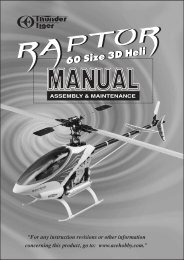
TAILS<br />
INSTALL THE FUEL TANK<br />
Tiger Trainer MK<br />
TAILS<br />
o<br />
90<br />
A<br />
A'<br />
A=A'<br />
21.Assemble the fuel tank by first cutting the silicone<br />
tube to 2-1/2'' in length. Press the straight plastic nipple<br />
(the 90 degree nipple is not used in this plane) into the<br />
rubber stopper (Saliva will ease insertion.) Now slip the<br />
silicone tubing onto the nipple and insert the metal clunk<br />
into the other end of the tubing. Insert this assembly into<br />
the tank (clunk first) and securely tighten the threaded<br />
cap on to hold everything together.<br />
24.Put the windshield on the front fuselage. It is held in<br />
place with eight 2X5 wood screws. You will need to drill<br />
a 1/16'' pilot hole for each screw first. Glue the window<br />
onto the windshield with CA.<br />
INSTALL THE TAIL GROUP<br />
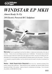
27. Use ruler to decide the center of stab and make<br />
marks. With the main wing centered on the fuselage,<br />
position the horizontal stab first then you can see the<br />
marks you drew through the slot. Then, position vertical<br />
fin. Use a felt trip pen or marker to draw lines along the<br />
fuselage sides. Do not forget drawing lines at the<br />
bottom side of stab.<br />
The fin is perpendicular to the stab. Both stab tips to the<br />
main wing are equal from the rear view (A=A')<br />
22. Attach a 6'' piece of standard fuel line (not furnished)<br />
to both the fuel outlet nipple and the vent nipple on the<br />
tank.<br />
Slide the fuel tank (cap end first) into the front of the<br />
fuselage, threading the fuel lines through the oblong<br />
hole in the firewall. The tubing coming from the tank's<br />
fuel outlet (center) goes to the carb and the tubing from<br />
the vent (upper) goes to the muffler's pressure fitting.<br />
Trim the length as needed. The tank fits tightly in the<br />
former.<br />
25.Remove the elevator and rudder and glue the hinges<br />
into the control surfaces using the same technique<br />
outlined for the ailerons.<br />
28.Remove the stab and fin from the fuselage and use a<br />
hobby knife to carefully score the covering material<br />
where marked. Make the score approximately 1/16''<br />
inside the lines you drew. It is very important that you do<br />
not press hard enough to cut into the wood itself or the<br />
stabilizer may fail in flight. Just score the covering and it<br />
will peel away nicely.<br />
In a similar fashion, remove the covering material on the<br />
vertical fin.<br />
30. Remove the covering on the slot. The rudder and<br />
elevator pushrods have already been pre-assembled at<br />
the factory. Insert the rudder pushrods which is bent at<br />
the thread end , thread end first, into the fuselage and<br />
exits the slot on the top of the rear fuselage. Locate the<br />
clevis, thread the clevis onto the threaded end at least<br />
1/4'' in length.<br />
23.Locate the windshield and window. Trim the<br />
windshield and window along with the molded cutting<br />
line with curved scissors.<br />
26. Trim away the covering from the slot at the rear of<br />
fuselage where vertical fin and horizontal stab go.<br />
29.Glue the stab and fin to the fuselage with epoxy,<br />
keeping the stab and fin in position as diagram shown.<br />
31.Locate the control horns and 2X12mm screws. Snap<br />
the clevis onto the control horns. Now position this horn<br />
onto the Rudder in such a way that the nyrod runs<br />
straight and the holes in the control horn are in line with<br />
the hinge line of the stabilizer. Mark the location of the<br />
control horn mounting holes on the elevator. Next, drill<br />
5/64'' holes where marked.<br />
10<br />
11
RADIO<br />
Tiger Trainer MK<br />
CONTROL THROWS<br />
INSTALL THE RADIO<br />
32.Cut the control horn as photo shown.<br />
33. Carefully cut a hole with hobby knife at the tail as the<br />
elevator pushrod exit.<br />
36. Mount three servos on the servo tray which is<br />
already installed in your fuselage. Note their orientation<br />
in the photo. Follow your radio's instruction manual and<br />
make sure you use the grommets, eyelets, and screws<br />
furnished with your radio. Drill 1/16'' pilot holes for the<br />
mounting screws before insertion.<br />
39.Hookup to the ailerons is via a nylon horn that is<br />
threaded onto the torque rod that is already installed in<br />
the wing. Screw the horn down until there is about 1/16''<br />
of threads exposed above the horn. Use threaded rods<br />
with clevises on the end for the linkage. Bend a “Z” bend<br />
on the servo end of the rod at the proper length so you<br />
have neutral aileron when the servo is centered.<br />
42.Correctly install the prop in front of the spinner<br />
backplate using the engine prop washer and prop nut.<br />
Note that the spinner backplate has two little posts that<br />
must be rotated up against the prop blade before the<br />
spinner will fit on. Rotate the prop counter clockwise<br />
until it is vertical when it is against the engine's<br />
compression stroke. Securely tighten the prop nut using<br />
a prop wrench or correctly fitting wrench. It is not a good<br />
idea to use pliers when tightening the prop nut! Attach<br />
the spinner to the spinner backplate using the two<br />
3x12mm self tapping screws provided.<br />
CONTROL THROWS<br />
37.Now it is time to hook the servos up to the control<br />
surface. Install the pushrod connector onto the<br />
outermost hole in the rudder servo arm as shown. To do<br />
so, remove the servo arm from the servo place the<br />
pushrod connector so the threaded portion exits the<br />
bottom of the servo arms. Secure in place using a 2mm<br />
washer and nut.<br />
40.Using the switch cover as a template, cut an opening<br />
in the side of the fuselage to mount the switch in. It<br />
should be on the left side of the fuselage. Drill two 1/16''<br />
holes for the switch mounting screws and install the<br />
switch.<br />
There are 1/4'' holes in both fuselage sides in front of<br />
the behind the wing opening for the wing hold-down<br />
dowels. Cut the covering away from these holes and<br />
install the two wing hold down dowels in these holes.<br />
Make sure the direction of servo moves correctly. If not<br />
switch the reversing switch on the transmitter. If the<br />
control surface does not move far enough, either move<br />
the pushrod out farther on the servo horn or move the<br />
clevis in farther on the control horn. If the control<br />
surface moves too much, either move the pushrod in on<br />
the servo horn or move the clevis out farther on the<br />
control horn. Adjust the control throws as following<br />
suggested.<br />
Aileron-Low Rate<br />
3/8",9.5mm<br />
34.Use control horn as template and drill 5/64'' holes<br />
with the control horn in line with the hinge line of<br />
elevator and right at the pushrod exit.<br />
Aileron-High Rate<br />
3/8",9.5mm<br />
1/2",12mm<br />
1/2",12mm<br />
Elevator-Low Rate<br />
3/8",9.5mm<br />
3/8",9.5mm<br />
35. Mount the control horn with 2X12mm screws. Insert<br />
the elevator pushrod with clevis threaded on. Cut a<br />
small piece of silicone and slide it onto the clevis. Then,<br />
snap the clevis on the outmost hole of control horn.<br />
38. Do the same procedure on throttle servo arm.<br />
Ensure that the hole for the pushrod wire is parallel to<br />
the length of the fuselage. Align the pushrod tube with<br />
the servo. The pushrod tube should not extend all the<br />
way to the servo as this would cause the pushrod to<br />
bind during operation. To shorten the pushrod tube,<br />
remove any excess length with a sharp hobby knife<br />
accordingly. Insert the pushrod wire through the<br />
pushrod connector. Secure in place using a 3mm set<br />
screw. Carefully adjust the control throws as page 13<br />
and 14 shown.<br />
41.Wrap your receiver and battery with packing foam<br />
which is available at local hobby shop. Install the<br />
receiver and battery in the front of the servo tray.<br />
Receiver is near the servo tray and battery is far from<br />
the servo tray as shown.<br />
Drill a 1/16'' hole through the fuselage side, about one<br />
inch behind the switch mount. From the inside out,<br />
thread the receiver antenna through this hole. You may<br />
want to tie a knot in the antenna 3'' or 4'' from the<br />
receiver to act as a strain relief. Attach the end of the<br />
antenna to the top of the vertical fin with a small #10<br />
rubber band and a T-pin. Maintain only a slight amount<br />
of tension on the antenna wire.<br />
Elevator-High Rate<br />
Rudder<br />
Nose Wheel<br />
1/4"Left<br />
1/4"Right<br />
1/2",12mm<br />
1/2",12mm<br />
7/8",22mm<br />
7/8",22mm<br />
12<br />
13
BALANCE<br />
Tiger Trainer MK<br />
PRE-FLIGHT CHECKS<br />
Barrel Closed<br />
Grasp the throttle pushrod, and while looking at the<br />
opening in the top of the carburetor, adjust the pushrod<br />
until the throttle barrel( inside ) is all the way closed.<br />
Tighten the setscrew in the pushrod connector to secure<br />
the pushrod in that postion. Cut off the excess throttle<br />
pushrod approximately 1/2" past the EZ connector.<br />
Open Slightly<br />
Barrel Open<br />
With the radio system still on, move the throttle trim<br />
lever up the middle. This should open the carburetor<br />
barrel up slightly(1/32"-1/16") and allow the engine to<br />
idle satisfactorily. To shut the engine off from the<br />
transmitter, simply move the throttle stick and trim lever<br />
all the way down. Now move the throttle stick up and<br />
watch the carburetor barrel. It should reach full open at<br />
the same time the stick reaches it end point. If it does<br />
not follow the instructions below. If the barrel does not<br />
open all the way, move the pushrod in one hole in the<br />
carburetor throttle arm. If the carburetor barrel reaches<br />
full open and makes the servo " hum" very early in the<br />
transmitter sticks movement, move the pushrod<br />
connector in on the servo horn( to a hole that is closer to<br />
the center of horn).<br />
N40TT<br />
BALANCING YOUR PLANE<br />
Tiger<br />
IMPORTANT- Do not attempt to fly your model before<br />
completing this every important section. A model that is<br />
not properly balanced will be unstable and could cause<br />
serious damage and /or injury.<br />
The balance point for this model is 3-1/2'' behind the<br />
leading edge of the wing. Measure this distance and<br />
mark it on both sides of the fuselage right under the wing.<br />
With your model fully assembled but without fuel, pick it<br />
up with your index fingers at each of the two balance<br />
marks you made earlier. If balanced properly, the plane<br />
will hang horizontally. If the plane hangs with the tail<br />
down, then you need to add (or redistribute) some<br />
weight in the nose. Usually the plane will either balance<br />
or hang slightly tail heavy. The easiest cure for a tailheavy<br />
plane is to move the receiver and battery forward<br />
as far as possible. If the plane hangs nose down, then<br />
you need to add some weight to the tail. Stick-on lead<br />
weights are available from your hobby dealer that will<br />
make adding weight a simple task. Once you have<br />
everything positioned as necessary, wrap your receiver<br />
and battery pack in 1/4'' or 1/2'' thick foam for protection.<br />
PRE-FLIGHT<br />
3 1/2”<br />
If you are an experienced pilot, some of the following<br />
text will not apply to you. Simply disregard references<br />
to “your first flights”.<br />
LOCATE A GOOD FLYING SITE<br />
Generally, the best place to fly your model is at AMA<br />
(Academy of Model Aeronautics) charactered club field.<br />
Your local hobby dealer can tell you if there is such a<br />
club a club in your area or write the AMA for information.<br />
It is also a good idea to join this organization before<br />
flying your model since they offer liability insurance that<br />
can protect you if your model causes damage or injury<br />
to others.<br />
Academy of Model Aeronautics<br />
5151 East Memorial Dr.<br />
Muncie, In 47302-9252<br />
If there is not a chartered club field in your community,<br />
you will need to find a large area free of obstructions,<br />
which has a smooth grass or asphalt surface to be used<br />
as a runway. For safety's sake, it should be located well<br />
away from houses, building schools, power lines and<br />
airport. If you will be flying within 6 mile of an airport,<br />
you should check with the airport manager before flying<br />
your model.<br />
A NOTE ON BATTERIES<br />
The batteries are the heart of your radio system. Make<br />
sure you have fully charged batteries! With<br />
rechargeable batteries, follow the manufacturers<br />
instructions to make sure the batteries are fully charged,<br />
especially the first time the radio is used.<br />
If your radio uses dry cells, make sure your batteries are<br />
in new condition. You have a lot of money invested in<br />
this project so it is not worth the risk of using old<br />
batteries.<br />
PRE-FLIGHT CHECKS<br />
You should perform these checks before each flying<br />
session.<br />
1. Check all control surfaces for possible looseness or<br />
deterioration.<br />
2. Check all screws, rubber band, clevises, nuts and all<br />
other connectors to make sure they are securely<br />
fastened.<br />
3. Check which radio frequencies are being used. Do not<br />
turn your radio until absolutely sure you are the only one<br />
operating on that frequency.<br />
4. Check for proper operation of all control surfaces.<br />
5. Check the level of charge in both the transmitter and<br />
receiver batteries before flying.<br />
6. Range check the radio both with and without the<br />
engine running! Follow the radio manufacturer's<br />
instructions for this.<br />
FLYING<br />
Learning to fly a radio control aircraft can be very exiting,<br />
but it is important that you thoroughly understand the<br />
basics of flight and controls before you attempt your first<br />
flights. Therefore, we highly recommend that you seek<br />
the expertise of an experienced instructor pilot for the<br />
first few flights. He (or she ) can get you in the air much<br />
more smoothly than trying everything yourself for the<br />
first time.<br />
GETTING ORIENTED<br />
We recommend that you find a large smooth and clear<br />
surface to practice taxing your airplane around in before<br />
you try to take off. To taxi, you only need to use the<br />
rudder stick. At the slow speeds encountered during<br />
taxing, the elevator and ailerons will not be effective.<br />
The first and most important thing to remember when<br />
controlling model aircraft is: the model controls are set<br />
up to operate as if you were sitting in the cockpit of the<br />
model. This means that when you pull back (down) on<br />
the elevator stick the nose of the plane will go up.<br />
Moving the rudder stick to the right will “yaw” the plane<br />
to the right and moving the aileron stick to the right will<br />
“roll” the plane to the right. Pretty simple right? Well, not<br />
quite. Since you are really standing on the ground and<br />
not sitting in the plane, this is how the controls work<br />
when you are facing the same direction the plane is<br />
flying. The problem is that when the plane is flying<br />
towards you, the rudder and aileron controls seem<br />
reversed to the inexperienced pilot. This is the reason<br />
we recommend that you practice taxing around in a large<br />
open area to try and get used to the control reversal.<br />
During your first few flights, try to face the direction that<br />
the plane is flying and looking over your shoulder as<br />
needed. This makes it a little easier to pretend that your<br />
sitting in the cockpit.<br />
FIRST FLIGHT<br />
When you are comfortable with the controls, you should<br />
be ready for your first flight. Go over the Pre-Flight<br />
Check List one more time for good measure and taxi out<br />
the runway (hopefully with an experienced pilot by your<br />
side). Point the model directly into the wind and<br />
gradually increase the throttle to full throttle. As the<br />
model starts rolling forward it may try to turn to the left<br />
due to the engine torque. Apply enough right rudder to<br />
keep the plane rolling relatively straight into the wind. If<br />
you built the model with right thrust, this tendency may<br />
not be noticeable. As the plane picks up speed, the right<br />
rudder input can be reduced.<br />
Once the plane reaches flying speed, it will probably try<br />
to fly by itself. If the grass seems to be impeding take off ,<br />
a very slight amount of “up” elevator can be applied, but<br />
it is very important that you do not apply too much up<br />
elevator too early or the plane will stall and roll over into<br />
the ground.<br />
As the plane becomes airborne, reduce the “up” elevator<br />
and allow the plane to pick up flying speed while gently<br />
gaining altitude. Once a safe flying speed and altitude<br />
has been obtained, feel free to turn the airplane back<br />
toward the flying field. Make all control inputs smoothly<br />
and gradually so you can see the effect they have on the<br />
plane. A small amount of “up” elevator will need to be<br />
applied to keep plane level during turns. You should be<br />
able to reduce the throttle to about ½ throttle for normal<br />
cruising flight which will reduce the flying speed and<br />
give you more time to think about what is going on. You<br />
will find that once airborne, you can fly the plane with<br />
only the aileron and elevator sticks. This is perfectly fine<br />
and will make it much easier for you to learn.<br />
If the plane has a tendency to turn, roll, climb, or dive,<br />
you can adjust the transmitter trims to correct this. On<br />
your first flights, it might be a good idea to have an<br />
experienced pilot make the adjustments for you while<br />
you fly the plane.<br />
14<br />
15