Introduction åè¨Maintenance Manual & Parts ... - Powertoys
Introduction åè¨Maintenance Manual & Parts ... - Powertoys
Introduction åè¨Maintenance Manual & Parts ... - Powertoys

Create successful ePaper yourself
Turn your PDF publications into a flip-book with our unique Google optimized e-Paper software.
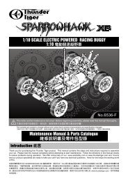
1/10 SCALE BRUSHLESS POWERED RACING BUGGY<br />
1:10 <br />
The contents are subject to change without prior notice due to product improvements and specificatrion changes.<br />
<br />
<strong>Introduction</strong> <br />
Maintenance <strong>Manual</strong> & <strong>Parts</strong> Catalogue<br />
<br />
No.6542-F<br />
This radio control model car is not a toy! Before beginning assembly, please read this manual thoroughly.<br />
<br />
Thank you for purchasing this Thunder Tiger product. This manual contains the steps and instructions required to assemble<br />
your car. Please read this manual completely before attempting to start maintenance. Follow the directions in this manual closely<br />
to reduce problems during operation. We offer online help on our www.acehobby.com or www.thundertiger.com and forums<br />
and our product specialists are ready to take your call if you have any technical questions. Have fun and enjoy the exciting world<br />
of R/C.<br />
SPARROWHAWK XXB <br />
<br />
<br />
24 www.thundertiger.com
Safety Precautions <br />
Please read all of the instructions and familiarize yourself with the product and its controls before operation.<br />
1. This product is not a toy. It is a high performance model car therefore it is important to familiarize yourself with the model,<br />
its manual, and its construction before assembly or operation. Adult supervision is necessary for children operating this<br />
model.<br />
2. Always keep this instruction manual on hand during assembly and for operating reference.<br />
3. Do not use a power screwdriver to install screws into plastic parts. A power screwdriver’s high rotation speed can heat<br />
up the screw being installed which can result in some melting of the plastic parts or stripped threads.<br />
4. For best performance, it is important to make sure all the moving parts can move freely without binding.<br />
5. This product, its parts, and its assembly tools can be harmful to your health. Always exercise extreme caution when<br />
assembling and operating this product. Keep away from any high speed rotating parts during operation.<br />
<br />
1. <br />
2. <br />
3. <br />
4. <br />
5. <br />
<br />
Index <br />
<strong>Manual</strong> Format <br />
Symbols Used Throughout The <strong>Manual</strong> <br />
STEP1 Rear Differential <br />
STEP2 Slipper Clutch <br />
STEP3 Rear Bulkhead Unit <br />
STEP4 Rear Suspension <br />
STEP5 Front Bullkhead Unit <br />
STEP6 Front Suspension <br />
STEP7 Shock Absorber <br />
STEP8 Steering Bellcrank <br />
STEP9 Installation of Rear End <br />
STEP10 Installation of Front End <br />
STEP11 Steering Servo <br />
P.2<br />
P.2<br />
P.3<br />
P.3<br />
P.4<br />
P.4<br />
P.6<br />
P.7<br />
P.10<br />
P.12<br />
P.13<br />
P.13<br />
P.14<br />
STEP12 Steering Servo <br />
STEP13 Installation of Motor Mount <br />
STEP14 Installation of Top Plate <br />
STEP15 Installation of Battery Pack <br />
STEP16 Receiver & E.S.C <br />
STEP17 Tire/Wheels <br />
STEP18 Body Shell <br />
SPARROWHAWK XXB EXPLODED VIEW <br />
SPARROWHAWK XXB PART <br />
SPARROWHAWK XXB OPTION PART <br />
BODY SHELLS <br />
WHEEL & TIRE OPTION PART LIST <br />
OPTIONAL ELECTRONICS <br />
P.15<br />
P.15<br />
P.16<br />
P.16<br />
P.17<br />
P.17<br />
P.18<br />
P.19<br />
P.22<br />
P.27<br />
P.30<br />
P.31<br />
P.32<br />
Tools Included <br />
Hex Wrenches<br />
1.5 / 2.0 / 2.5 / 3.0mm<br />
<br />
4-Way Cross Wrench<br />
<br />
Tools Required For Assembly <br />
Philips Screwdrivers<br />
(L/M/S)<br />
<br />
Needle Nose Pliers<br />
<br />
Wire Cutter<br />
<br />
Hobby Knife<br />
<br />
CA<br />
Lexan Body Curved Scissor<br />
<br />
Ruler<br />
<br />
Super Glue<br />
(CA Glue)<br />
<br />
Thread Locking Adhesive<br />
(Threadlocker)<br />
<br />
Grease<br />
<br />
1
<strong>Manual</strong> Format<br />
<br />
How to read the instruction manual?<br />
<br />
A:<br />
B:<br />
C:<br />
D:<br />
A:<br />
B:<br />
C:<br />
D:<br />
The manual indicates the assembly step<br />
number and the parts that are to be assembled.<br />
The manual displays actual size drawings, and<br />
part quantities used.<br />
All parts, except screws, are identified by their<br />
order numbers. When purchasing spare parts,<br />
identify the part required and cross reference<br />
this to the spare parts list in the end of this<br />
manual, which shows the spare parts and the<br />
corresponding order numbers.<br />
This instruction manual uses several symbols.<br />
Pay careful attention to them during<br />
construction. Details are given at the bottom<br />
of each page.<br />
<br />
<br />
<br />
<br />
<br />
<br />
Example <br />
STEP4<br />
1 10x15x4mm<br />
Ball Bearing<br />
<br />
2 6mm<br />
Ball Stud<br />
<br />
3 Caster Block Bushing<br />
C<br />
4 3x12mm<br />
BT Machine Screw<br />
<br />
Front Suspension <br />
4<br />
2<br />
4<br />
4<br />
B<br />
C<br />
Marked "L"<br />
"L"<br />
In the chassis set, these dog bones have been assembled in one-piece unit.<br />
<br />
4<br />
4<br />
A<br />
D<br />
1<br />
C<br />
2<br />
3<br />
3<br />
1<br />
Symbols Used Throughout The <strong>Manual</strong><br />
<br />
C.A<br />
oil<br />
x2<br />
L R<br />
Apply C.A Glue<br />
<br />
Apply silicon oil<br />
<br />
Assemble as many times as specified<br />
<br />
Assemble left and right side the same way<br />
<br />
Cut off shaded portion<br />
<br />
Ensure smooth, non-binding movement when assembling<br />
<br />
Pay close attention here<br />
<br />
Cut off excess<br />
<br />
1<br />
2<br />
3<br />
Assemble in right order<br />
<br />
Drill holes with the specified diameter<br />
<br />
Hint<br />
<br />
Apply threadlocker<br />
<br />
Apply grease<br />
<br />
x<br />
Must be purchased separately<br />
<br />
2
STEP1<br />
1 2.5x12mm<br />
F/H Philip Machine Screw<br />
<br />
Front Differential / Rear Differential <br />
8<br />
4<br />
X2<br />
2<br />
4<br />
5 5<br />
2 8x14x4mm<br />
Ball Bearing<br />
<br />
3 3x5mm<br />
Washer<br />
<br />
4<br />
4<br />
5<br />
4<br />
6<br />
4<br />
5<br />
1<br />
4 5x8mm<br />
Washer<br />
<br />
3<br />
3<br />
1<br />
5 4.4x0.8mm<br />
O-Ring<br />
O<br />
4<br />
silicon oil<br />
<br />
1<br />
1<br />
2<br />
6 3x19mm<br />
Pin<br />
<br />
1<br />
You may also use silicone oil to replace grease for the<br />
differentials. Fill up to 80%. Change the viscosity of the silicone<br />
oil according to track conditions and your driving style.<br />
<br />
<br />
<br />
<br />
STEP2<br />
Side View<br />
<br />
Slipper Clutch <br />
7mm<br />
Standard<br />
<br />
1 3x4mm<br />
Set Screw<br />
<br />
1<br />
1<br />
2<br />
x<br />
Optional<br />
<br />
2 2.5 mm<br />
E-clip<br />
E<br />
3<br />
2<br />
3<br />
3 5x11x4 mm<br />
Ball Bearing<br />
<br />
1<br />
Hint<br />
<br />
Apply grease<br />
<br />
X2<br />
Assemble as many times<br />
as specified<br />
<br />
x<br />
Must be purchased separately<br />
<br />
3
STEP4<br />
Rear Suspension <br />
Rear Shock Tower<br />
<br />
2<br />
1 6 mm(L)<br />
Ball Stud (PD9104)<br />
<br />
4<br />
1<br />
2 3x8 mm<br />
BT Philip Machine Screw<br />
<br />
2<br />
4<br />
3 3x16 mm<br />
BT Philip Machine Screw<br />
<br />
1<br />
3<br />
STEP5<br />
Front Differential Unit <br />
1 5x11x4 mm<br />
Ball Bearing<br />
<br />
2<br />
1<br />
3<br />
1<br />
Leave one unit of drive axle for<br />
next step.<br />
<br />
2 4 mm<br />
E-clip<br />
E<br />
1<br />
2<br />
1<br />
3 2.5 mm<br />
E-clip<br />
E<br />
Hint<br />
<br />
6
STEP7<br />
Shock Absorber <br />
1 2.5mm<br />
E-Clips<br />
E<br />
8<br />
1<br />
3<br />
2<br />
Attach the shock eyelet onto<br />
the shock shaft until it<br />
reaches the mark line on<br />
the shaft.<br />
<br />
<br />
2 Shock Eyelet<br />
<br />
4<br />
1<br />
3<br />
8<br />
4 or 5<br />
3 2.8x1.9 mm<br />
O-Ring<br />
O<br />
4 Shock Shaft<br />
<br />
5 Shock Shaft<br />
<br />
2<br />
2<br />
Cover the shaft with cloth<br />
before griping it with pliers.<br />
<br />
<br />
<br />
X2<br />
Front x2<br />
2<br />
X2<br />
Rear x2<br />
2<br />
silicon oil<br />
<br />
Piston<br />
<br />
Pull down the piston and<br />
slowlly fill in the silicon oil.<br />
The factory set-up of the<br />
shock is #500 of silicon oil<br />
for the front and rear shock<br />
absorbers.<br />
<br />
<br />
<br />
<br />
#500<br />
Then gently move the shaft/piston<br />
up and down to get rid of the<br />
bubbles.<br />
<br />
<br />
Add silicon oil one<br />
more time up to the<br />
brim.<br />
<br />
<br />
Put the shock bladder onto<br />
the shock body, wipe off<br />
excess oil and tighten the<br />
shock cap.<br />
<br />
<br />
<br />
X4<br />
Ensure the piston moves<br />
smoothly<br />
<br />
<br />
X2<br />
Front x2<br />
2<br />
Rear x2<br />
2<br />
1mm<br />
2mm<br />
4mm<br />
6mm<br />
Use 6 mm preload spacer for front. Use 8 mm preloadd spacer for rear.<br />
6mm<br />
Compress the spring<br />
an d install spring cup.<br />
<br />
<br />
X4<br />
Hint<br />
<br />
Apply silicon oil<br />
<br />
X2 X4<br />
Assemble as many times as specified<br />
<br />
10
STEP7<br />
Shock Absorber <br />
Front Shock Absorbers<br />
<br />
Rear Shock Absorbers<br />
<br />
11
STEP8<br />
1 6mm(L)<br />
Ball Stud<br />
<br />
2 Swing Post Screw<br />
<br />
Steering Bellcrank <br />
3<br />
2<br />
4<br />
1<br />
3<br />
2<br />
1<br />
3<br />
2<br />
Top View<br />
<br />
Rear<br />
<br />
3 5x8x2.5mm<br />
Ball Bearing<br />
<br />
3<br />
Side View<br />
<br />
3<br />
Rear<br />
<br />
Note direction<br />
<br />
STEP8<br />
Steering Bellcrank <br />
Side View<br />
<br />
32.5 mm<br />
Apply grease<br />
<br />
Pay close attention here<br />
<br />
12<br />
Ensure smooth, non-binding movement<br />
when assembling
STEP11<br />
Steering Servo <br />
1<br />
3x10mm<br />
F/H Self-Tapping Screw<br />
<br />
1<br />
Marked "T"<br />
"T"<br />
2<br />
6mm(S)<br />
Ball Stud<br />
<br />
1<br />
2<br />
Neutral<br />
<br />
1<br />
Steering Servo Type<br />
<br />
ACE R/C S1903/S2008MG<br />
ACE R/C DS1015/DS1313<br />
Airtronics / Sanwa / JR / KO<br />
Futaba<br />
Hitec<br />
Servo Hom Mount<br />
<br />
T<br />
T<br />
A<br />
T<br />
H<br />
Marked "T" for Thunder Tiger stock servo. Find the appropriate servo horn<br />
mount for your servo from the chart. Install the servo horn arm with the stock<br />
mounting screw. See the graphic for the correct neutral angle.<br />
"T"<br />
<br />
90<br />
STEP11<br />
Steering Servo <br />
1<br />
3x10mm<br />
F/H Philip Machine Screw<br />
<br />
2<br />
1<br />
1<br />
14
STEP16<br />
Receiver & E.S.C. <br />
Anntenna<br />
<br />
Thread antenna cord<br />
through the tubing.<br />
<br />
<br />
STEP17 Tire/Wheels <br />
X4<br />
Tire insert foam<br />
<br />
Install the tire onto the wheel. Glue the tire to the wheel with instant glue in four spots around the tire on both sides.<br />
<br />
Warning: Follow the adhesive instructions for proper use and safety. Wear eye and hand protection.<br />
<br />
Hint<br />
<br />
Apply C.A Glue<br />
<br />
X4<br />
Assemble as many times as specified<br />
<br />
17
STEP17 Tire/Wheels <br />
1<br />
4x12mm<br />
Socket Hex Machine Screw<br />
<br />
4<br />
2<br />
1<br />
2 4mm<br />
Washer<br />
<br />
4<br />
2<br />
1<br />
STEP18 Body Shell <br />
2<br />
1<br />
1<br />
2<br />
1 3x8mm<br />
BT Self-Tapping Screw w/washer<br />
<br />
2<br />
Body Clip<br />
R<br />
2<br />
2<br />
Receiver Antenna Hole<br />
<br />
Position the connectors here.<br />
<br />
Hint<br />
<br />
Apply threadlocker<br />
<br />
18
SPARROWHAWK XXB PARTS <br />
2344 BL MOTOR IBL36/39-540C<br />
<br />
PD7034 MOTOR PINION GEAR,20T<br />
20T<br />
PD7712 ANTENNA BAG<br />
<br />
PD7837 MOTOR MOUNT<br />
<br />
PD7845 CHASSIS<br />
<br />
PD7846 SERVO MOUNT<br />
<br />
PD7847 BATTERY BRACE<br />
<br />
PD7864 OUTDRIVE CUPS<br />
<br />
PD7901 FRONT BULK SET<br />
<br />
PD7902 REAR BULK SET<br />
<br />
PD7905 DIFF SPUR GEAR 44T<br />
<br />
PD7915 FRONT TOE PLATE<br />
<br />
x4 x8 x4<br />
PD7916 REAR TOE PLATE<br />
<br />
PD7917 FRONT SUSP. ARMS<br />
<br />
PD7918 REAR SUSP. ARMS<br />
<br />
PD7920 SUSP. ARM MOUNT BUSHING<br />
<br />
x4<br />
x2<br />
x2<br />
PD7921 INNER HINGE PIN SET<br />
<br />
PD7924-T FRONT SHOCK SET<br />
<br />
PD7925-T REAR SHOCK SET<br />
<br />
PD7926 SHOCK BODY SET<br />
<br />
x2<br />
x2<br />
(2)<br />
(2)<br />
(2)<br />
PD7927 SHOCK SHAFT<br />
<br />
PD7931 BUMPER<br />
<br />
22<br />
PD7932 FRONT WHEEL 33mm(B)<br />
()<br />
PD7933 FRONT TIRE W/FOAM 33mm
SPARROWHAWK XXB PARTS <br />
(2)<br />
(2)<br />
(2)<br />
PD7934 REAR WHEEL 43mm(B)<br />
()<br />
PD7935 REAR TIRE W/FOAM 43mm<br />
<br />
PD7936-1 SHOCK TOWER SET<br />
<br />
PD7937 BALL STUD SPACER<br />
<br />
x4<br />
x8<br />
x4<br />
x2<br />
x2<br />
PD7938 REAR WING MOUNT<br />
<br />
PD7947 SHOCK BLADDER<br />
<br />
PD7954 METAL TURNBUCKLE SET<br />
<br />
PD7962-R SHOCK SPRING(R)<br />
<br />
x4 x4 x4<br />
x2<br />
x2<br />
PD7998 BULK LOWER COVER<br />
<br />
PD8098 SHOCK PISTON SET<br />
<br />
PD9051 DIFFERENTIAL CASE<br />
<br />
PD9077 STEERING BLOCK SET<br />
<br />
x8 x8 x8<br />
PD9078 CASTER BLOCK SET<br />
C<br />
PD9080 OUTER HINGE PIN SET<br />
<br />
PD9082 SUSP. ARM MOUNT BUSHING<br />
<br />
PD9086 SWING RACK SET<br />
<br />
x4 x4 x4<br />
x4 x4 x4<br />
x8<br />
PD9087 SWING POST SCREW<br />
<br />
PD9090 HUB CARRIER SET<br />
<br />
PD9102 SHOCK ACCESSORIES, MMGT<br />
<br />
PD9103 SHOCK EYELET, TA<br />
<br />
x4 x4 x4<br />
PD9107 STEER SERVO HORN SET<br />
<br />
PD9110 HXE ADAPTER SET<br />
<br />
23<br />
PD9178 DIFF GEAR SET<br />
<br />
PD9179 DRIVE PINION SET 13T
CFRP=CARBON FIBER REINFORCED PLATE<br />
ALUM=ALUMINUM<br />
SPARROWHAWK XXB OPTION PARTS <br />
(4)<br />
(4)<br />
(4)<br />
1340 ROTATING CAR STAND, O<br />
<br />
PD2302 TIE END SET<br />
<br />
PD7713 LONG HEX ADAPTER<br />
<br />
PD7722 ALUM STEERING BLOCK SET<br />
<br />
PD7723 ALUM CASTER BLOCK SET<br />
C<br />
PD7724 ALUM HUB CARRIER SET<br />
<br />
PD7876 ALUM HEX ADAPTER<br />
<br />
PD7877 AL BATT. STRAP SCREW<br />
<br />
Also see PD7877<br />
6.8 COILS<br />
6.8 <br />
(2)<br />
(2)<br />
PD7878 CFRP BATT. STRAP<br />
<br />
PD7928 SHOCK SPRING(B)<br />
()<br />
PD7951-T REAR TOE PLATE SET<br />
(2/ 3)<br />
PD7957 CFRP FRONT SHOCK TOWER<br />
<br />
Also see PD8098 / PD7927<br />
Also see PD8098 / PD7927<br />
(2) (2)<br />
9.4 COILS<br />
9.4 <br />
(2)<br />
(2)<br />
PD7958 CFRP REAR SHOCK TOWER<br />
<br />
PD7960 FRONT ALUM SHOCK BODY SET<br />
<br />
PD7961 REAR ALUM SHOCK BODY SET<br />
<br />
PD7962-L SHOCK SPRING(L)<br />
()<br />
1.8 2<br />
PD7965-1 REAR SWAY BAR SET(GOLD)<br />
()<br />
PD7965-2 REAR SWAY BAR SET(BLACK)<br />
()<br />
PD7967 CFRP BULK LWR COVER<br />
<br />
PD7968 ALUM STEERING BELL CRANK<br />
<br />
Also see PD9191<br />
Also see PD9231<br />
PD7969 ALUM STEERING SLIDER<br />
<br />
PD9156 HEX WHL CAP SCREW<br />
<br />
PD9188 CFRP CHASSIS<br />
<br />
PD9189 CFRP TOP PLATE<br />
<br />
27
WHEEL & TIRE OPTION PARTS LIST <br />
(2) (2)<br />
(2)<br />
(2)<br />
PD7952-W FRONT WHEEL (WHITE)<br />
()<br />
PD7953-W REAR WHEEL (WHITE)<br />
()<br />
PD7952-O FRONT WHEEL 33mm(O)<br />
()<br />
PD7952-Y FRONT WHEEL 33mm(Y)<br />
()<br />
(2)<br />
(2)<br />
PD7953-O REAR WHEEL 43mm(O)<br />
()<br />
PD7953-Y REAR WHEEL 43mm(Y)<br />
()<br />
PART# DESCRIPTION <br />
NOTE<br />
PD7952-W<br />
PD7953-W<br />
PD7952-O<br />
PD7952-Y<br />
PD7953-O<br />
PD7953-Y<br />
FRONT WHEEL (WHITE)<br />
REAR WHEEL (WHITE)<br />
FRONT WHEEL 33mm (ORANGE)<br />
FRONT WHEEL 33mm (YELLOW)<br />
REAR WHEEL 43mm (ORANGE)<br />
REAR WHEEL 43mm (YELLOW)<br />
<br />
<br />
<br />
<br />
<br />
<br />
31
C<br />
2009<br />
JD7248