SLAB TRACK
SLAB TRACK
SLAB TRACK

Create successful ePaper yourself
Turn your PDF publications into a flip-book with our unique Google optimized e-Paper software.
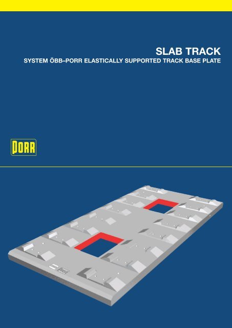
<strong>SLAB</strong> <strong>TRACK</strong><br />
SYSTEM ÖBB–PORR ELASTICALLY SUPPORTED <strong>TRACK</strong> BASE PLATE
GENERAL<br />
The slab track (ST), system ÖBB–PORR elastically supported<br />
track base plate, has been jointly developed by the Austrian<br />
Railway Corporation (ÖBB) and Allgemeine Baugesellschaft –<br />
A. Porr AG. Since 1995 it has been the obligatory system in<br />
Austria and since 2001 it has also been used in the construction<br />
of bridges and tunnels in Germany. No problems have<br />
occurred on the tracks already in operation, covering a distance<br />
of approximately 100 km. The oldest section has been<br />
in operation for 17 years without maintenance and service<br />
costs.<br />
<strong>TRACK</strong> BASE PLATE (TP)<br />
CONSTRUCTION<br />
The principal element of this system is the elastically supported<br />
track base plate. The track-base-plate-system ÖBB–PORR is<br />
based on a 5,16 m long pre-fabricated reinforced concrete<br />
plate with untensioned reinforcement. Thus eight pairs of<br />
supporting points type Vossloh 300-1 are integrated at intervals<br />
of 65 cm. The sole of the plate as well as the tapered<br />
grouting openings are provided with an elastic layer for<br />
decoupling. This results in a reduction in the vibrations emitted<br />
into the foundation (damping of structure-borne noise).<br />
The system weighs 1 t per linear meter and is therefore a light<br />
mass-spring-system.<br />
PRODUCTION, STORAGE AND TRANSPORT<br />
Production is made in a prefabrication plant and/or a field<br />
plant and is therefore independent of weather conditions. Due<br />
to a complete quality assurance system a constant high quality<br />
is guaranteed and documented. The used steel formworks<br />
are adjustable and so they completely cover all radii ranges.<br />
Reductions, block outs, coverings, dowels etc. can be foreseen<br />
with millimetre accuracy using adequate layers. Due to<br />
the “just-in-time-principle” storage place is as a rule provided<br />
in the company plant only. From there the track base plates<br />
are normally transported to their destination by wagon. The<br />
5 t heavy plates are fastened using a special traverse grabbing<br />
into the grouting opening. Each of the track base plate<br />
types is unmistakably marked with a corresponding bar code<br />
set in concrete and can therefore be easily identified at any<br />
time if intermediate storage is necessary. The unloading is<br />
handled with the necessary unloading equipment (portal<br />
crane or lorry with crane) or with any other lifting device if<br />
intermediate storage is essential.<br />
Production of track base plates in prefabrication plant<br />
<strong>TRACK</strong> BASE PLATE SYSTEM ÖBB–PORR<br />
Length 5,16 m (2,56 up to 5,16m)<br />
Width 2,40 m (2,10 up to 2,40m)<br />
Depth 16 cm (16 / 24 cm)<br />
Openings 91 x 64 cm (top)<br />
87 x 60 cm (bottom)<br />
Weight: 50,00 KN (gross)<br />
51,40 KN (using Vossloh 300-1)<br />
Types: Linear (R>3697 m)<br />
Radii (R=200 up to 3697m)<br />
Railway/suburban railway/underground<br />
Rail: 60E1 (E2) / S54 / S48U<br />
Optional intermediate storage of track base plates<br />
2
<strong>SLAB</strong> <strong>TRACK</strong>, SYSTEM<br />
“<strong>TRACK</strong> BASE PLATE ÖBB–PORR”<br />
ASSEMBLING<br />
The slab track system ÖBB–PORR elastically supported track<br />
base plate, is built on a solid or low-subsidence base structure<br />
such as, for example, a tunnel invert, bridge construction<br />
or hydraulically bond base layer on mass spring systems. As<br />
a rule, the grouting thickness is > 8 cm and therefore the substructure<br />
height up to the upper edge of the track is 60 E1<br />
(E2) > 47,3 cm. Through the tapered grouting openings a<br />
positive locking compound of the track base plate and the<br />
concrete joint sealing compound is achieved.<br />
240<br />
160 80<br />
≥80<br />
60E1(E2)<br />
elastic layer<br />
elastic<br />
track bed<br />
earth connection<br />
2.400<br />
640<br />
concrete joint<br />
sealing compound<br />
reinforcement<br />
concrete joint sealing<br />
compound opening<br />
5.200<br />
track supporting component<br />
650 650 650 650 650 650 650<br />
Slab track system ÖBB–PORR – cross section + top view<br />
If a modified concrete joint sealing compound without reinforcement<br />
is used (> 4 cm), a construction height of > 43,3 cm<br />
60 E1 (E2) can be achieved if necessary. This ensures the<br />
essential flexibility, for example, to optimise cross sections of<br />
tunnels and bridges or to realise track lowering in order to<br />
obtain a bigger cross section (clearance) in already existing<br />
old tunnels (for example Arlbergtunnel and Tauerntunnel).<br />
Unlike sleeper systems, track base plates can provide big<br />
block outs, for example for revision and bearing shafts wherever<br />
needed. Block outs of 1,80 m x 0,80 m have already<br />
been utilized in the tunnel of the north-south-connection in<br />
Berlin. By reduction of the track base plates, cable crossings<br />
of 250 mm width can be planned.<br />
640<br />
upper edge of<br />
the track 0.00<br />
rough clean surface -- invert concrete<br />
920<br />
393<br />
≥473<br />
elastic<br />
layer<br />
concrete subbase<br />
tubbing segment<br />
track base plate<br />
concrete joint<br />
sealing<br />
compound<br />
8 16 23<br />
50 1.800<br />
50<br />
30 1.800<br />
30<br />
2 2<br />
chequer plate 7/9 zinc-dipped<br />
upper edge of<br />
the track 0.00<br />
18 18<br />
-1.32<br />
block out<br />
1800/700<br />
drainage piping<br />
Block out in track base plate for pump shaft – longitudinal section<br />
BASIS FOR MEASUREMENTS AND SPECIFICATIONS<br />
ACCORDING TO EUROCODE (EC)<br />
Vertical loads<br />
Freight train UIC 71<br />
Heavy load train SW 0 acc. UIC 776-1E<br />
Speed v = 250 km/h (A) respectively v = 330 km/h<br />
Axle weight P max stat. = 250 kN at v = 120 km/h<br />
Wear out per support point:<br />
Q dyn = 125 x 1,67 x 1,25 = 261 kN<br />
Horizontal loads<br />
Side shock H = 100kN, but horizontal force in<br />
a mounting axle H = 60 kN; effects of starting<br />
and braking<br />
Reinforcement<br />
Proportion of steel approximately 6 % - mild<br />
steel 550, in case of mild steel 500 appropriately<br />
higher<br />
Quality of concrete<br />
Track base plates<br />
C 30/37 / XC3 / XF3 / XA1L / GK 16 / F 52<br />
Concrete joint sealing<br />
compound > 8 cm<br />
C 25/30 / XC3 / XF3 / XA1L / GK 8 / F 73 (scc)<br />
C 25/30 / XC3 / XF3 / XA1L / GK 16 / F 73 (scc)<br />
Concrete joint sealing<br />
compound > 4 cm<br />
C 55/67 / XC3 / XF1 / XA1L / GK 4 / F 73 (scc)<br />
1.836<br />
Weather conditions<br />
Besides the safe carrying of the loads of the<br />
railway traffic, the absorption of environmental<br />
influences (temperatures) and the discharge of<br />
surface flood water has to be secured reliably<br />
on a long term basis. The track base plates are<br />
connected with each other only by the passing<br />
through tracks enabling a length compensation<br />
within the 40 mm wide joints. Therefore any<br />
deformations caused by temperature cannot<br />
cause any damage. Furthermore the joints can<br />
also be used for drainage.<br />
-1.55<br />
zinc-dipped angle iron<br />
-0.47<br />
incline concrete<br />
3
MODE OF OPERATION<br />
The bedding necessary for the load distribution on the track is<br />
guaranteed by the elasticity of the track mounting. In addition<br />
the elastic rubber granulate layer, amounting to approximately<br />
10 % of the total elasticity, has the effect that high forces are<br />
well distributed and causes a reduction of the stress in the<br />
multi-layered system.<br />
Portal crane<br />
Bedding of the supporting points and track base plates under traffic load<br />
0,00<br />
bedding measured in 6 MP /<br />
calculated according to stress application<br />
-0,50<br />
-1,00<br />
bedding in mm<br />
-1,50<br />
-2,00<br />
-2,50<br />
-3,00<br />
-3,50<br />
-4,00<br />
MP1 MP2 MP3 MP4 MP5 MP6 MP7 MP8 MP9 MP10 MP11 MP12<br />
Laying of track base plates with lorry<br />
PRODUCTION<br />
Laying<br />
free bearing<br />
stressed track<br />
under consideration for plate bedding<br />
Laying of under traffic load<br />
The laying of the track base plates, which have a width of just<br />
2,40 m (2,10 m), is normally done with portal cranes. This<br />
enables the plates to be lifted forwards in the smallest possible<br />
space. In addition, no reloading or intermediate storage is<br />
necessary, because the plates can be taken directly from the<br />
transport wagon. In the case of islands or missing track connection,<br />
the take over and the laying of the track base plates<br />
by lorry with loader arm is the usual practice.<br />
In any case, the track base plates are being laid at the destination<br />
with an accuracy of + 1 cm in order to minimize the<br />
work needed to adjust them.<br />
Adjustment of tracks<br />
After the partial spreading of the tracks positioned at the side,<br />
the work of adjusting the final track begins by using a M36-<br />
spindle. This method guarantees precise track set accuracy in<br />
setting the track requiring no further correction.<br />
Adjustment work is further reduced by an adequate track<br />
geometry of the track base plates. Therefore the time involved<br />
for the adjustment is reduced by up to 50 % in comparison to<br />
other slab track systems.<br />
4
Concrete pumps up to 500 m<br />
DAMAGE CONCEPT<br />
Concrete<br />
Measurement of track positioning with track measurement wagon<br />
A further advantage of the elastic layer is its separation from<br />
the concrete. Therefore the two tapered grouting openings,<br />
which prevent a lift off of the track base plate, can be cut free<br />
or chiselled out and the track base plates can be replaced<br />
separately within three to four hours.<br />
According to the space available, the concrete joint sealing<br />
compound is applied either directly or through a hose pump<br />
up to a maximum of 500 m. The use of a self-compacting concrete<br />
joint sealing compound enables a holohedral embedding<br />
of the track base plate. As a result of the vibration-free concreting<br />
process (without vibrator), the fine-tuning of the track unit<br />
is not affected. Furthermore, it is possible for these slab tracks<br />
to be installed in a short railway block (example: East-West-<br />
Connection Berlin 2002) due to the fast setting process of the<br />
scc-concrete. The concrete joint sealing compound is adequately<br />
reinforced in order to limit wide cracks.<br />
Cut out – top view + longitudinal section<br />
Concreting of track base plate with scc (self compacting concrete)<br />
Lifting – top view – longitudinal section<br />
5
Concreting of refurbishment-track base plate – top view + longitudinal view<br />
BASE STRUCTURES<br />
TUNNEL FLOOR<br />
Tunnel floors have normally no or little subsidence and<br />
they are therefore an ideal base structure for slab tracks.<br />
The slab track system ÖBB–PORR elastically supported<br />
track base plate can be directly mounted onto the tunnel<br />
floor. For surface dewatering every 50 m, or in the portal<br />
areas every 25 m, semi-troughs are put diagonally into the<br />
concrete joint sealing compound. The remaining spaces<br />
up to the top layer of the concrete are usually filled with<br />
gravel or concrete.<br />
Slab track in shield section<br />
BRIDGE<br />
Bridge girder systems can, like tunnel floors, be used as a<br />
direct base structure for the slab track. The horizontal pressure<br />
is transferred within a narrow radius into the bridge construction<br />
by the use of concrete blocks. In Austria it is refrained from<br />
the labour-intensive application of concrete blocks.<br />
1,5%<br />
Noise absober track<br />
Track base plate “ÖBB-PORR”<br />
Concrete joint sealing comound<br />
Elastomer structure<br />
Supporting structure<br />
Balast<br />
2%<br />
Ballast<br />
Concrete blocks<br />
Track axle<br />
Bridge axle<br />
Track axle<br />
Tunnel axis<br />
Bridge with slab track on Elastomer mat – sectional view<br />
1.600 1.700<br />
1.520<br />
3.300<br />
1.680<br />
86.0 66.0 1.730 1.570<br />
74.0 94.0<br />
45.5 32.5<br />
78.0<br />
Ballsting<br />
Track base plate<br />
SOK ±0.00<br />
Concrete joint se al ing compound<br />
+0,18<br />
-0.60<br />
Shield section – Sectional view<br />
Berlin – Main station – Lehrter railway bridges with slab track<br />
6
Essential differences occur due to the rather high deformation,<br />
by disfigurement or shrinkage, caused by temperature<br />
differences, subsidence, or traffic loads as well as creep and<br />
shrinkage. Especially at the bridge joints deformations can<br />
cause unacceptably high track tension and lifting of track supporting<br />
points. In such cases special track-crossing constructions<br />
are necessary in order to reduce deformations to an<br />
acceptable extent. For example, on the 25 bridge girder systems<br />
of the east-west-connections, a total of 50 special trackcrossing<br />
constructions were built, and twelve joining areas<br />
were directly built over with slab tracks (on extensive sliding<br />
bearings).<br />
Track 60E1(E2)<br />
Track base plate<br />
A<br />
Longitudinal member<br />
Track base plate<br />
Cross member<br />
EARTH STRUCTURE<br />
The laying of earth structures is done on a load distribution<br />
plate or a hydraulically bond supporting layer. Based on the<br />
high degree of prefabrication of the track base plates and the<br />
relatively small grouting openings, quality influences due to<br />
weather conditions are kept fairly low. This also applies to<br />
mounting on bridge constructions.<br />
Rail axle<br />
Partial<br />
drainage pipe<br />
made of concrete<br />
DN 200 drainage material<br />
ballast<br />
Absorbing plates<br />
Track axle<br />
Concrete joint<br />
sealing<br />
comound<br />
Upper edge<br />
of track<br />
± 0,00<br />
Bitumen cating<br />
Balast,<br />
granulate 1<br />
washed<br />
2:3<br />
49<br />
6%<br />
Steel concrete distribution<br />
plate d = 30 cm<br />
-0.80<br />
20 2.40 20<br />
Soil exchange<br />
Bitumen cating<br />
WU concrete (C25/30)<br />
Elastically supported<br />
track base plate<br />
210 210<br />
A<br />
Open section – cross section<br />
Section A-A<br />
Track 60E1(E2)<br />
Steel wedge<br />
Concrete<br />
49<br />
Bearing<br />
4x longitudinal member<br />
Cross member<br />
Bearing<br />
79.2 70.6 79.2<br />
Track crossing construction – longitudinal section + cross section<br />
Track crossing construction (track support structure)<br />
Slab track – Open section<br />
7
MASS SPRING SYSTEMS<br />
In case of increased demands on protection against structureborne<br />
noise, the system can be layered on a mass spring<br />
trough (example: cross section mass spring system in tunnel)<br />
or in case of lower construction heights, directly on the extensive<br />
elastomer support (example: cross section mass spring<br />
system on bridge).<br />
The possibility of making block outs in any part of the track<br />
base plate, enables a space-saving positioning of the bearing<br />
shafts in the track axle.<br />
Elastomer mat<br />
Elastomer mat<br />
Track axle<br />
Concentric noise absorber<br />
Track base plate<br />
Concrete joint sealing compound<br />
Elastomer mat<br />
Supporting<br />
structure<br />
Concrete block<br />
Noise absorber at the<br />
edges<br />
Balast<br />
2%<br />
Slab track on extensive elastomer bearing (mass<br />
spring system without trough) – sectional view<br />
Due to the low height of the system (> 47,3 cm), mass spring<br />
systems without troughs can be produced for low construction<br />
heights, for example 25 Hz on approximately 50 cm. On<br />
the bridges of the main station Lehrter Bahnhof, a softer elastomer<br />
was applied in the centre of the concrete blocks area,<br />
unlike in the side areas, in order to avoid punching.<br />
Bearing shaft with bearings when lifting the mass trough<br />
Rail 60E1 (E2)<br />
Steel concrete mass trough<br />
elastic singel bearings<br />
Slab track in shield section – cross section<br />
Application of elastomer<br />
8
ADAPTATION OF ADDITIONAL EQUIPMENT<br />
The track base plates provide a prefabricated bearing surface<br />
with millimetre accuracy, for example, in order to absorb the<br />
noise of traffic and railway crossings. Therefore, dowels with<br />
millimetre accuracy, can be used, for example, for guard rails,<br />
ADAPTATION OF ADDITIONAL EQUIPMENT<br />
blockages, track magnets and conductor rails. In areas of frequency<br />
control, the reinforcement can be insulated against<br />
outside influences.<br />
Noise absorber<br />
Section A-A<br />
Track magnet<br />
Thread rod<br />
Adapter plate<br />
Guard rail<br />
Anchorage device<br />
Base plate<br />
Compensating plate<br />
Elastomer base plate<br />
Elastomer<br />
base plate<br />
Section B-B<br />
Blockage<br />
Conductor rail support REHAU<br />
height adjustable<br />
Adapter plate<br />
Elastomer base plate<br />
Compensation plate<br />
Adapter plate<br />
Compensation plate<br />
Elastomer base plate<br />
Section C-C<br />
Coated reinforcement<br />
for example using AGROVAN 209<br />
C<br />
C<br />
B B<br />
A A<br />
Additional equipment of the track slab system ÖBB-PORR – sectional view + top view<br />
9
TRANSITION FROM BALLAST TO <strong>SLAB</strong><br />
<strong>TRACK</strong><br />
Transition from ballast to slab track system, “track base plate<br />
ÖBB–PORR”, is carried out according to the standard catalogue<br />
for building slab tracks (4th edition) or in accordance<br />
TRANSITION FROM BALLAST TO <strong>SLAB</strong><br />
<strong>TRACK</strong><br />
with the ÖBB regulation RZ no. 17220. The ballast area is<br />
solidified by the use of a well-tried procedure with synthetic<br />
resin.<br />
Österreich RZ 17220<br />
Section A-A<br />
65 65<br />
Section B-B<br />
60 ca. 60<br />
ca. 30<br />
60<br />
6.5<br />
Track base plate<br />
Concrete joint sealing compound<br />
24.5<br />
Concrete subbase<br />
Hydralically<br />
bond foundation<br />
Hydralically<br />
bond foundation<br />
Upper edge<br />
of foundation<br />
Upper edge<br />
of foundation<br />
Elastic bond ballast<br />
Slabtrack<br />
Ballast<br />
Slabtrack (FF)<br />
Track base plate<br />
Slab Track with<br />
prestressed-concrete sleepers<br />
Number of sleepers 2,4 m long<br />
8 straight<br />
16 bent<br />
Ballast<br />
15 reinforced concrete sleepers<br />
2,60 m long<br />
15m<br />
20 Stk. Point concrete sleepers<br />
12.00 m<br />
Ballast with<br />
standard sleepers<br />
Trackform 60E1(E2)<br />
60<br />
Tuxiliary track: track form 60E1(E2)<br />
60<br />
60<br />
2.800<br />
2.400<br />
A<br />
A<br />
B<br />
B<br />
65<br />
65<br />
60<br />
60<br />
Elastically bonded ballast 30.00 m - 35.00 m<br />
Full bonding 2.60 m wide approx<br />
0,15 m deep 7.2 m<br />
Partial bonding: (1) rail foot 0.7-0.8 m wide, 0.15 m deep<br />
2. Every second space 0.15 m deep<br />
≥22.8 m<br />
Surface bonding includes strip along sleeper ends, 0.2-0.3 m wide and 0.2-0.3 m deep<br />
30.00 m - 35.00 m<br />
Transition area slab track / ballast (Germany) – longitudinal section, top view + sectional view<br />
10
REFERENCES<br />
Finally, the ÖBB–PORR slab track system, is impressive<br />
because of the visible concrete quality of the prefabricated<br />
REFERENCES<br />
parts and because its application has now been maintenancefree<br />
for over 17 years.<br />
PROJECT YEAR SPECIFIC FEATURES <strong>TRACK</strong> LENGTH<br />
Langenlebern 1989 Test track in the field 264 m<br />
Tauerntunnel 1992 Tunnel refurbishment track 2 2.629 m<br />
Helwagbrücke 1993 New bridge construction 52 m<br />
Galgenbergtunnel 1996/1997 New tunnel construction, light mass spring system, bridge 11.040 m<br />
Römerbergtunnel 1997 New tunnel construction, light and medium mass spring system 638 m<br />
Zammertunnel 1998/1999 New tunnel construction, light and medium mass spring system 4.477 m<br />
Kaponigtunnel 1999 New tunnel construction and bridge, light mass spring system 11.170 m<br />
By-pass Melk 1999/2000 Wachbergtunnel, Melker tunnel, bridge 9.042 m<br />
and field, light mass spring system<br />
Wolfsgrubentunnel/Arlbergtunnel 1999/2000 New tunnel construction, medium mass spring system 3.730 m<br />
Siebergtunnel 2000/2001 New tunnel construction 12.902 m<br />
S7-Rennweg Airport 2001/2002 New tunnel construction, medium mass spring system 3.250 m<br />
Blisadonatunnel 2002 New tunnel construction 4.865 m<br />
Tauerntunnel 2002/2003 Tunnel refurbishment track 1 + 2 9.880 m<br />
Unterwaldertunnel 2003 New tunnel construction 2.480 m<br />
Junction Rohr 2003 New tunnel construction 1.691 m<br />
Junction Wagram 2003 New tunnel construction 2.870 m<br />
Lehrter Bahnhof 2001/2002 Bridges/light mass spring system track base plate on 4.690 m<br />
(east-west-connection)<br />
slide bearings 50 joint crossing constructions<br />
Lehrter Bahnhof 2002/2006 New tunnel construction / light, medium and heavy 8.944 m<br />
(north-south connection)<br />
and heavy mass spring system / big block outs<br />
Birgl- and Kennlachtunnel 2004 New tunnel construction and light mass spring system 2.650 m<br />
Pistentunnel S7 2005 New tunnel construction, medium and heavy mass spring system 1.412 m<br />
Lainzer Tunnel 2006/2007 under construction 4.550 m<br />
Arlbergtunnel 2007/2009 under construction 20.812 m<br />
TOTAL<br />
124.038 m<br />
11
ABAP Ref. 317B / 02.07 / 0,25 M Fotos: PORR-Archiv<br />
PORR TECHNOBAU UND UMWELT AG<br />
A-1103 Vienna, Absberggasse 47<br />
Tel. 0043 (0)50 626-1509 | Fax 0043 (0)50 626-1651<br />
www.porr.at | bahnbau@porr.at<br />
The reference brochures of the PORR Group (from ABAP Nr. 217 on) can be downloaded from www.porr.at