Bruksanvisning Step in Room MkIV med Dixell fra 11/2010 ver 9.5
Bruksanvisning Step in Room MkIV med Dixell fra 11/2010 ver 9.5
Bruksanvisning Step in Room MkIV med Dixell fra 11/2010 ver 9.5

You also want an ePaper? Increase the reach of your titles
YUMPU automatically turns print PDFs into web optimized ePapers that Google loves.
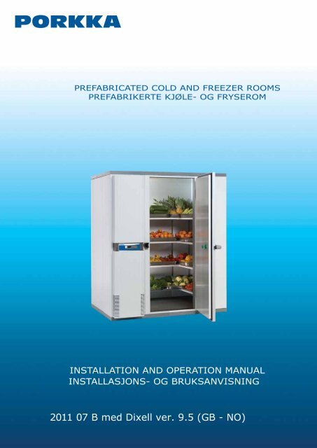
PREFABRICATED COLD AND FREEZER ROOMS<br />
PREFABRIKERTE KJØLE- OG FRYSEROM<br />
INSTALLATION AND OPERATION MANUAL<br />
INSTALLASJONS- OG BRUKSANVISNING<br />
20<strong>11</strong> 07 B <strong>med</strong> <strong>Dixell</strong> <strong>ver</strong>. <strong>9.5</strong> (GB - NO)
ENGLISH<br />
THESE INSTRUCTIONS ARE FOR PREFABRICATED COLD<br />
AND FREEZER ROOMS.<br />
IT IS VERY IMPORTANT TO READ THESE INSTALLATION<br />
AND OPERATING INSTRUCTIONS CAREFULLY BEFORE<br />
YOU START USING THE EQUIPMENT FOR THE FIRST TIME.<br />
ALSO, PLEASE KEEP THESE INSTRUCTIONS IN A SAFE<br />
PLACE FOR FUTURE REFERENCE OR USE BY ANOTHER<br />
OPERATOR.<br />
To reset the maximum and m<strong>in</strong>imum<br />
temperature recorded 10<br />
LARM SIGNALS <strong>11</strong><br />
MAINTENANCE 13<br />
HOW TO CHANGE THE LIGHT BULB 13<br />
OPERATIONAL FAULTS 13<br />
DISPOSAL OF UNIT AT THE END OF ITS<br />
WORKING LIFE 14<br />
GUARANTEE 14<br />
MODULAR COLD, MEDIUM AND FREEZER ROOMS ARE<br />
MANUFACTURED FOR THE STORAGE OF CHILLED AND<br />
FROZEN GOODS. THEY ARE NOT DESIGNED FOR<br />
FREEZING OR CHILLING DOWN OF HOT FOODSTUFFS, OR<br />
OTHER ITEMS.<br />
IN THIS INSTRUCTION MANUAL, MEASURES HAVE BEEN<br />
DESCRIBED RELATING TO THE INSTALLATION AND DAILY<br />
USE OF THE PRODUCT. YEARLY MAINTENANCE AND<br />
REPAIRS HAVE TO BE DONE BY AN AUTHORIZED SERVICE<br />
COMPANY. THE USER IS NOT ALLOWED TO REMOVE ANY<br />
OTHER COVERS OF THE PRODUCT THAN THE BOTTOM<br />
PANEL (PAGE 12) AND THE PROTECTIVE CAP OF THE<br />
LAMP (PAGE 13). ALL THE COVERS OF THE PRODUCT<br />
HAVE TO BE PROPERLY FASTENED IN PLACE BEFORE<br />
SWITCHING ON THE PRODUCT.<br />
BY FOLLOWING THESE INSTRUCTIONS YOU CAN<br />
IMPROVE THE PRODUCT’S PERFORMANCE AND REDUCE<br />
UNNECESSARY REPAIR COSTS. PLEASE NOTE! IT IS<br />
IMPORTANT TO HAVE YOUR EQUIPMENT REGULARLY<br />
MAINTAINED BY A PROFESSIONAL ENGINEER.<br />
YOU WILL FIND THE TERMS OF GUARANTEE ON PAGE 14.<br />
RECEIPT<br />
Check that you have the correct number of packages as listed<br />
<strong>in</strong> the despatch note. Although e<strong>ver</strong>y care has been taken and<br />
our pack<strong>in</strong>g material used is the best available, should there be<br />
any transport damage dur<strong>in</strong>g deli<strong>ver</strong>y to site, sign the deli<strong>ver</strong>y<br />
note stat<strong>in</strong>g your doubt or clause it “goods damaged” on receipt.<br />
Notify the supplier im<strong>med</strong>iately and confi rm <strong>in</strong> writ<strong>in</strong>g with<strong>in</strong> 5<br />
days.<br />
The manufacturer’s guarantee does not co<strong>ver</strong> damages<br />
caused by transportation!<br />
TABLE OF CONTENTS<br />
RECEIPT 2<br />
SITING (VENTILATION) 3<br />
ASSEMBLY 3<br />
ROOM WITH STANDARD FLOOR 3<br />
FLOORLESS COLDROOM (SRC-<strong>Room</strong>) 4<br />
INSTALLING DOOR FRAME HEATER PLUG ON<br />
FREEZER MODELS 5<br />
THE FLOOR HEATING ON FREEZER<br />
MODELS 5<br />
HOW TO MOUNT THE LAMP 5<br />
TO MOUNT THE CONTROL PANEL 6<br />
CHANGING THE HINGING OF THE DOOR 6<br />
INSTALLATION OF THE SHELVES 7<br />
PLACING OF GOODS IN THE COLD/FREEZER<br />
ROOMS 8<br />
ELECTRICAL CONNECTIONS 8<br />
OPERATION 8<br />
RHDS-SYSTEM 8<br />
OPERATION: COMBINED ELECTRONIC<br />
CONTROL BOARD AND TEMPERATURE DISPLAY 9<br />
Keys 9<br />
To lock and unlock the keyboard 9<br />
Function of key lamp lights 9<br />
Function of the display lights 9<br />
Stand-by 10<br />
Adjust<strong>in</strong>g the temperature 10<br />
Defrost 10<br />
Manual defrost 10<br />
To check m<strong>in</strong>imum temperature 10<br />
To check maximum temperature 10<br />
Pic. 1. Package<br />
2
SITING (VENTILATION)<br />
Before erect<strong>in</strong>g the room ensure there is suffi cient ventilation <strong>in</strong><br />
the area where rooms is to be positioned. In operation the room<br />
will dissipate a heat load <strong>in</strong> the area <strong>in</strong> question <strong>in</strong> region of<br />
1 - 2,1 kW per hour when runn<strong>in</strong>g. This heat must be removed<br />
from the area by means of ventilation such as lou<strong>ver</strong>s or<br />
extraction systems. If impractical, consult your supplier for the<br />
possibilities of us<strong>in</strong>g our heat disposal system.<br />
The refrigeration systems are designed to operate satisfactorily<br />
<strong>in</strong> ambients between +5 and 32°C. Ensure that the fl oor area<br />
to be used is level. Requirement of the eveneness is max ±3<br />
mm/m. Correct any unevenness at this time. It is recommended<br />
to leave a gap of 50mm m<strong>in</strong>imum between a freezer room and<br />
the fabric of the surround<strong>in</strong>g build<strong>in</strong>g for air circulation<br />
purposes.<br />
ENGLISH<br />
The fl oor under the freezer room should be treated aga<strong>in</strong>st<br />
moisture and ice. If needed, the fl oor elements can be<br />
deli<strong>ver</strong>ed with fl oor heat<strong>in</strong>g elements (optional accessory).<br />
Before unpack<strong>in</strong>g ensure there is suffi cient space where the<br />
room is to be assembled, this <strong>in</strong>cludes height.<br />
ASSEMBLY<br />
Beg<strong>in</strong> <strong>in</strong>stallation by tak<strong>in</strong>g packages as close to proposed site<br />
as possible. When open<strong>in</strong>g packages use correct tools and<br />
wearsuitable personal protection equipment <strong>in</strong>clud<strong>in</strong>g gloves.<br />
Before commenc<strong>in</strong>g <strong>in</strong>stallation acqua<strong>in</strong>t yourself with the<br />
operation of the panel locks. Us<strong>in</strong>g the allan key provided, turn<br />
the tongue of the lock outwards, note the double action, where<br />
the last part of the turn pulls the panels tightly together. Return<br />
the lock to the orig<strong>in</strong>al position. (pic. 2).<br />
It is recommended that the coldroom fl oor is sealed to the site<br />
fl oor with a mastic type solution, to prevent <strong>in</strong>crass of moisture/<br />
<strong>ver</strong>m<strong>in</strong>. The same applies to pl<strong>in</strong>th sections on fl oor-less rooms.<br />
Remember the site fl oor must be cabable of support<strong>in</strong>g the<br />
coldroom and produce weight without distortion.<br />
Pic.2. Panel lock<br />
Pic.3. The assembly of the unit<br />
FOLLOW PANEL<br />
PLAN LAYOUT<br />
DRAWING!<br />
ROOM WITH STANDARD FLOOR<br />
Place the fl oor panel or panels <strong>in</strong> situ, tighten the locks and<br />
check the sides of the fl oor are <strong>in</strong> l<strong>in</strong>e. Check aga<strong>in</strong> the fl oor<br />
is level, it must be correct before assembly of the wall panels<br />
beg<strong>in</strong>s. Unevenness will cause panels not to align and the door<br />
will not fi t correctly.With fl oorless rooms place pl<strong>in</strong>th on fl oor,<br />
ensur<strong>in</strong>g the corners are at true 90° angles, (follow tip given<br />
earlier) affi x pl<strong>in</strong>th us<strong>in</strong>g fi x<strong>in</strong>gs provided. Ensure they<br />
are level. Otherwise similar problems will occur as fl oored<br />
rooms. If the fl oor elements of a freezer room are equipped with<br />
fl oor heat<strong>in</strong>g elements (optional accessory), each element will<br />
have it’s own heater, which should have a power supply<br />
<strong>in</strong>dependent from the unit. The cables are <strong>in</strong>stalled to be taken<br />
out either from the side wall beh<strong>in</strong>d the unit or from the back<br />
wall.<br />
The heat<strong>in</strong>g cables are located <strong>in</strong>side the fl oor panel, on the<br />
bottom surface. In mount<strong>in</strong>g the panels, special care must be<br />
taken to prevent damag<strong>in</strong>g the cables.<br />
Check the condition of the heat<strong>in</strong>g cables before and after<br />
mount<strong>in</strong>g by measur<strong>in</strong>g the <strong>in</strong>sulation resistance between the<br />
conductor and jacket and the resistance of the heat<strong>in</strong>g cables.<br />
The correct resistance values can be found from the connection<br />
cable for the heat<strong>in</strong>g cable. Operat<strong>in</strong>g voltage is 230 V.<br />
3
ENGLISH<br />
Pic. 4. The assembly of the pl<strong>in</strong>ths<br />
Pic 5. Corner angle plates<br />
Pic. 6. L-brakets<br />
FLOORLESS COLDROOM (SRC-<strong>Room</strong>)<br />
When <strong>in</strong>stall<strong>in</strong>g a fl oorless coldroom, ensure that the corners do<br />
have an angle of 90°. FLOORLESS ROOMS ARE SUPPLIED<br />
WITH 90° ANGLE TO ENSURE CORNERS ARE STRAIGHT.<br />
IF UNSURE PLACE ROOF PANEL/PANELS ON FLOOR (IF A<br />
TWO OR THREE PIECE ROOF IS SUPPLIED ENSURE CAM<br />
LOCKS ARE TIGHTENED) THEN MARK AROUND. PLACE<br />
PLINTH ON FLOOR FOLLOWING MARKS FROM ROOF<br />
PANEL/PANELS, SECURE USING FIXINGS PROVIDED.<br />
FOR MORE DETAILED INSTRUCTIONS, PLEASE SEE THE<br />
TABLES OF BASE MOUNTING PROFILES IN THE END OF<br />
THIS MANUAL.<br />
• Place the two longest lengths of pl<strong>in</strong>th on the fl oor. Ensure the<br />
fl oor is level, some pack<strong>in</strong>g can be placed under pl<strong>in</strong>th<br />
sections to ma<strong>in</strong>ta<strong>in</strong> level. Us<strong>in</strong>g 90 o angle provided ensure<br />
corners are true.<br />
• Layout rest of pl<strong>in</strong>th sections provided, once aga<strong>in</strong> ensur<strong>in</strong>g<br />
corners are at a true 90° angles (pic.4). Check the outer<br />
dimensions will suit room be<strong>in</strong>g assembled. Drill holes<br />
through pl<strong>in</strong>th <strong>in</strong> to fl oor and secure with fi x<strong>in</strong>gs provided.<br />
NOTE: Leave 4 fi x<strong>in</strong>gs for door<strong>fra</strong>me supports.<br />
• Fix corner angle plates (pic. 5) with screws provided.<br />
• After erect<strong>in</strong>g cold room follow<strong>in</strong>g usual guidel<strong>in</strong>es given<br />
earlier, the sta<strong>in</strong>less steel co<strong>ver</strong>s can be attached with fi x<strong>in</strong>gs<br />
provided to co<strong>ver</strong> the ends of pl<strong>in</strong>th at door entrance, the<br />
shorter fl ange should be to the front (pic. 7). Fill any gaps with<br />
clear silicon mastic. The sta<strong>in</strong>less steel ‘L’ brackets can be<br />
fi xed <strong>in</strong>side the door to the fl oor and <strong>fra</strong>me to give strenght to<br />
the <strong>fra</strong>me <strong>fra</strong>me when trolleys are be<strong>in</strong>g used.<br />
Pic. 7. The assembly of the wall elements<br />
Pic 6. The assembly of the corner and roof elements<br />
Pic. 7. The Assembly of the door and the emergency door release<br />
The massive selection of rooms offered, dictates a large<br />
number of different panel widths and corner sizes are supplied.<br />
It is essential that you carefully study the plan draw<strong>in</strong>g detaill<strong>in</strong>g<br />
panel layout. This must be followed at all times.<br />
• Beg<strong>in</strong> the <strong>in</strong>stallation by position<strong>in</strong>g the cool<strong>in</strong>g unit to either<br />
front left or right hand of the rooms and mount on pl<strong>in</strong>th or<br />
fl oor. (Note care should be taken to ensure the unit is<br />
balanced and not fall o<strong>ver</strong>). Then place wall panel and<br />
build accord<strong>in</strong>g to plan.<br />
When <strong>in</strong>stall<strong>in</strong>g wall panels, pay attention to the follow<strong>in</strong>g:<br />
• Do not fully tighten cam-locks wall/fl oor, wall/wall, until the roof<br />
panel has been fi tted. This allows some movement to align all<br />
panels.<br />
• beg<strong>in</strong> the <strong>in</strong>stallation with the wall and corner panels adjacen<br />
to any exist<strong>in</strong>g brick walls, then fi t the rema<strong>in</strong><strong>in</strong>g panel<br />
sections.If possible do not <strong>in</strong>stall the mach<strong>in</strong>ery or door<br />
section last<br />
• before fi nal tighten<strong>in</strong>g of wall panel cam-locks and fi tt<strong>in</strong>g roof,<br />
ensure that the tops are level.<br />
• when <strong>in</strong>stall<strong>in</strong>g door panel, secure the handle to the door by<br />
screw<strong>in</strong>g the emergency release opener <strong>in</strong> to the lock<br />
mechanism through the door panel from the <strong>in</strong>side. Note take<br />
care not to cross-thread <strong>in</strong>ner release <strong>in</strong> the handle.<br />
Secure the emergency opener’s co<strong>ver</strong> plate with screw<br />
provided.<br />
ALWAYS CHECK SATISFACTORY FUNCTION OF<br />
EMERGENCY INNER RELEASE<br />
• Before fi tt<strong>in</strong>g roof panels ensure power cable for<br />
mach<strong>in</strong>ery unit is to the outside.<br />
• One piece roof panels can then be lifted <strong>in</strong>to place and locks<br />
tightened. If the roof is <strong>in</strong> sections, lift all roof panels <strong>in</strong><br />
place from rear forward or side by side and tighten roof<br />
sections together, the roof to wall panel lock can then also be<br />
tightened. All locks should now be fully tightened and the<br />
white seal caps can now be fi tted to all holes.<br />
4
Fasten the co<strong>ver</strong> plate of the mach<strong>in</strong>ery unit with white-heel pull<br />
rivets of Ø 3.2 mm.<br />
ENGLISH<br />
INSTALLING DOOR FRAME HEATER PLUG ON FREEZER<br />
MODELS<br />
On a freezer unit there will be a short cable with plug fi tted, this<br />
should be <strong>in</strong>serted <strong>in</strong> to the correspond<strong>in</strong>g socket next to the<br />
door <strong>fra</strong>me. A small amount of silicon can be used to seal the<br />
socket from any moisture penetration. Install the<br />
protector around the plug see the pic.10.<br />
Pic. 10. Door <strong>fra</strong>me heater plug protector<br />
THE FLOOR HEATING ON FREEZER MODELS<br />
The coupl<strong>in</strong>g of the freezer’s fl oor heat<strong>in</strong>g (optional) is electric<br />
<strong>in</strong>stallation subject to licence and have to be done by an<br />
authorized electrician. National orders concern<strong>in</strong>g electric<br />
<strong>in</strong>stallation are to be observed. Floor heat<strong>in</strong>g cables must not<br />
use the fuse that is common to the mach<strong>in</strong>e unit or other pieces<br />
of electrical equipment.<br />
HOW TO MOUNT THE LAMP<br />
3<br />
Remove the stopper screw (1) of the lamp globe and turn the<br />
globe (2) slightly so that it comes off the holders. Inside the<br />
globe there are a 60W light bulb (3) and two mount<strong>in</strong>g screws<br />
(4).<br />
Remove the refl ect<strong>in</strong>g plate (5) and connect the wire bayonet<br />
catches (6) together. Put the <strong>fra</strong>me back with mount<strong>in</strong>g screws<br />
(4). Do not put the extra wire <strong>in</strong>side the evaporator cas<strong>in</strong>g.<br />
Fasten the reflect<strong>in</strong>g plate (5) and screw the light bulb (3) back.<br />
Put the protective globe back <strong>in</strong> place and turn it slightly when<br />
you will be able to screw the stopper screw (1) back <strong>in</strong> place.<br />
4<br />
3<br />
2<br />
1<br />
4<br />
5<br />
6<br />
Picture <strong>11</strong>a. Parts of the lamp<br />
Picture <strong>11</strong>b. Mount<strong>in</strong>g of the lamp<br />
5
ENGLISH<br />
TO MOUNT THE CONTROL PANEL<br />
1 2<br />
Remove the control panel from shipp<strong>in</strong>g position attached to<br />
side wall (1). Attach panel <strong>in</strong> operational position (2).<br />
CHANGING THE HINGING OF THE DOOR<br />
The <strong>fra</strong>me has pre-fabricated holes for all the necessary screws<br />
to allow the change the h<strong>in</strong>g<strong>in</strong>g of the door afterwards. After the<br />
assembly work please co<strong>ver</strong> the unnecessary holes with the<br />
white plugs (packed <strong>in</strong>to the accessory kit).<br />
Installation of the lock counterpart (Pic. serie 12):<br />
Pic. serie 12.The lock counter part assembly<br />
Loosen the screw A. Please do not remove it. Detatch the p<strong>in</strong><br />
assembly from the body. Dur<strong>in</strong>g reassembly, please fi rst adjust<br />
the depth of the p<strong>in</strong> assembly before tighten<strong>in</strong>g the screw to<br />
ensure the proper function of the Jumbo-lock. Dismount the<br />
body of the lock’s counter part by remov<strong>in</strong>g the screws<br />
B (4 pcs). Dur<strong>in</strong>g reassembly, before tighten<strong>in</strong>g the screws,<br />
please adjust the sit<strong>in</strong>g of the counterpart. Dismount the base<br />
by remov<strong>in</strong>g the screws C. To reassemble <strong>in</strong> re<strong>ver</strong>se order.<br />
Installation of the h<strong>in</strong>ges (Pic. serie13):<br />
Open the door completely (180°) and place a support under the<br />
front corner to avoid any damages.<br />
Remove the h<strong>in</strong>ge co<strong>ver</strong> plates D (2 pcs/h<strong>in</strong>ge) by push<strong>in</strong>g<br />
gentle with a screw dri<strong>ver</strong>. There are screws E (4 pcs/h<strong>in</strong>ge)<br />
under the co<strong>ver</strong>s. By remov<strong>in</strong>g them you dismount the h<strong>in</strong>ges<br />
from the <strong>fra</strong>me.<br />
DO NOT REMOVE THE HINGES FROM THE DOOR<br />
LEAF<br />
Pic. serie 13. Assembly of the h<strong>in</strong>ges<br />
To reassemble <strong>in</strong> re<strong>ver</strong>se order. Before tighten<strong>in</strong>g the screws<br />
E, ensure the doorleaf is properly located <strong>in</strong> the middle of the<br />
<strong>fra</strong>me.<br />
ALWAYS CHECK SATISFACTORY FUNCTION OF THE<br />
EMERGENCY INNER RELEASE.<br />
56
INSTALLATION OF THE SHELVES<br />
ENGLISH<br />
1<br />
3<br />
8<br />
9b<br />
9a<br />
5<br />
7<br />
6<br />
2<br />
4a<br />
4b<br />
Ladder rails (1) are <strong>in</strong>stalled at the factory (excl. rails beh<strong>in</strong>d the unit <strong>in</strong> 1200 wide rooms).<br />
Fasten the wall bracket extension piece (9a) with attached connect<strong>in</strong>g part (9b) and M5 bolts (Note! <strong>Room</strong>s 2400/2440 mm high only).<br />
Fasten the end pieces (2) to the end of the support bars (3). If the shelf length is more than 2 meters, you must extend the pipes with a<br />
connector (8).<br />
Place the shelf supports (4a) at the correct height <strong>in</strong> the wall supports (1).<br />
Install the extension holder (4b) <strong>in</strong> its place (Note! <strong>Room</strong>s 1200 mm deep only).<br />
Llift the pipes o<strong>ver</strong> the shelf supports so that the protrusion of the end pieces of the pipes faces upwards (2).<br />
Please note the height of the shelves can be adjusted <strong>in</strong>dependently by 50 mm on each wall.<br />
Place the shelf plates (5) o<strong>ver</strong> the pipes so that the round<strong>in</strong>g on the edge of the plate faces the room.<br />
Note! Install the shelf plates accord<strong>in</strong>g to the layout draw<strong>in</strong>g.<br />
Centre the shelves by mov<strong>in</strong>g the pipes sideways. Then remove the last shelf plate of each row (6) and set the bar fasteners (7) as shown<br />
<strong>in</strong> the picture. Put the shelves back.<br />
Note! The maximum shelf load is 100 Kg of evenly distributed product per meter, per level i.e. 400 Kg per meter run.<br />
7
ENGLISH<br />
PLACING OF GOODS IN THE COLD/FREEZER ROOMS<br />
In plac<strong>in</strong>g goods, especially <strong>in</strong> the freezer room, special<br />
attention should be paid to suffi cient free air space around each<br />
package to ensure a proper air circulation. Do not place or stack<br />
packages or boxes <strong>in</strong> front of the air movement fan. Goods<br />
should be <strong>in</strong> closed packages.<br />
ELECTRICAL CONNECTIONS<br />
Before connect<strong>in</strong>g the mach<strong>in</strong>ery to ma<strong>in</strong>s electricity<br />
ensure that the voltage is the same as that shown on the<br />
refrigeration unit serial plate. Ensure a separate supply is<br />
provided for each room be<strong>in</strong>g <strong>in</strong>stalled. The refrigeration unit is<br />
supplied with a fl exible cable with a molded electrical plug top<br />
with fuse. Three phase models require an isolat<strong>in</strong>g switch fuse.<br />
AS THE CONDENSER COOLING AIR EXITS THE<br />
UNIT AT THE TOP IT IS ESSENTIAL THAT THE<br />
APERTURE IS NOT OBSTRUCTED WITH BOXES,<br />
PACKING MATERIAL ETC.<br />
TO AVOID EVAPORATOR DAMAGE IT IS<br />
IMPORTANT TO KEEP FOOD WHICH IS HIGH IN ACID<br />
SUCH AS VINEGAR BASED SAUCES OR VERY HIGH<br />
SALT CONTENT IN CLOSED LIDDED CONTAINERS.<br />
C 940, C 1240<br />
M 940, M 1240<br />
F 840<br />
F <strong>11</strong>40 240 V 50 Hz<br />
F 1540 400V 50 Hz<br />
13 A slow<br />
13 A slow<br />
13 A slow<br />
15 A slow<br />
3x16 A slow<br />
Installation of the ma<strong>in</strong>s cable (pic. 15). Plug the cable <strong>in</strong>to the<br />
socket located at the upper left corner of the unit (1). Install the<br />
upper front co<strong>ver</strong> and fasten it by the aid of the lock plate (2).<br />
Secure the lock plate by tighten<strong>in</strong>g the two screws.If a freezer<br />
room is equipped with fl oor heat<strong>in</strong>g cables, they should be<br />
connected to an <strong>in</strong>dependent power supply.<br />
OPERATION<br />
All refrigeration units are pre-tested <strong>in</strong> the factory and the<br />
operational temperatures can be adjusted as follows:<br />
a) coldrooms (C) +2°C/+12°C (34°F/50°F)<br />
b) chiller rooms (M) -2°C/+5°C (23°F/34°F)<br />
c) freezer rooms (F) -22°C/-18°C (-8°F/0°F)<br />
Before us<strong>in</strong>g the room check that the operational<br />
temperature is reached. If the operational temperature is not<br />
achieved read through the “Operational Faults” section of these<br />
<strong>in</strong>structions before you call <strong>in</strong> a ma<strong>in</strong>tenance eng<strong>in</strong>eer. A strong<br />
smell due to the clean<strong>in</strong>g agent or silicon mastic may appear <strong>in</strong><br />
the room, <strong>in</strong> which case the room should be washed with a mild<br />
detergent suitable for the purpose, then dried and ventilated for<br />
at least 24 hours.<br />
RHDS-SYSTEM<br />
Pic. 15. Installation of the cable and upper front co<strong>ver</strong>.<br />
DO NOT REMOVE ANY PANELS OR GUARDS OR THE<br />
ELECTRICAL CONTROL PANELS BEFORE<br />
DISCONNECTING THE UNIT FROM THE MAINS<br />
SUPPLY BY REMOVING THE PLUG OR THE FUSE<br />
FROM SOCKET.<br />
If a room is to be placed <strong>in</strong> an area where there is little or no<br />
ventilation you should consider select<strong>in</strong>g the unique Porkka<br />
‘Remote Heat<br />
Disposal System’. This is a method of remov<strong>in</strong>g waste refrigeration<br />
heat to either and external area or a more ventilated<br />
position and alleviates heat build-up where the equipment is<br />
situated, which <strong>in</strong> return reduces electrical consumption and<br />
operational costs.<br />
Please consult you Porkka sales offi ce for further <strong>in</strong>formation.<br />
8
COMBINED ELECTRONIC CONTROL BOARD AND<br />
TEMPERATURE DISPLAY<br />
The equipment is fi tted with a comb<strong>in</strong>ed digital temperature<br />
display with many built-<strong>in</strong> features which <strong>in</strong>clude; Data<br />
connections for HACCP monitor<strong>in</strong>g of equipment temperatures<br />
and alarms. Volt free relay either normally open or closed<br />
for connection to build<strong>in</strong>g ma<strong>in</strong>tenance alarm system or<br />
supervis<strong>in</strong>g system. XWEB (optional accessory) will allow<br />
HACCP compliance by logg<strong>in</strong>g temperature data, alarm history<br />
and will also allow remote control and advise on ma<strong>in</strong>tenance of<br />
the equipment.<br />
To lock and unlock the keyboard<br />
+ The keylock prevents un<strong>in</strong>tended use of the keys.<br />
The lock is switched on by hold<strong>in</strong>g the keys down<br />
att the same time for 3 seconds.The display<br />
momentarily shows letters “PoF”. With keylock<br />
on you can still check the lowest and highest<br />
temperature registered. The light switch function<br />
can still be used when keypad is locked (only on<br />
cab<strong>in</strong>ets fitted with lights). To unlock the keyboard<br />
keep the keys pressed together for more than<br />
3s. The “Pon” message will be displayed and the<br />
keyboard is unlocked.<br />
ENGLISH<br />
Dur<strong>in</strong>g normal operation the display will <strong>in</strong>dicate the cab<strong>in</strong>et<br />
<strong>in</strong>ternal air temperature or when ‘dEF is displayed when the<br />
cab<strong>in</strong>et is tak<strong>in</strong>g it’s automatic defrost period.<br />
Keys<br />
Function of key lamp lights<br />
KEYS MODE FUNCTION<br />
Yellow light on Dry<strong>in</strong>g function on<br />
Green light on<br />
Manual defrost<strong>in</strong>g is on<br />
The key starts dry<strong>in</strong>g function to reduce the eventual<br />
humidity on the <strong>in</strong>ner surfaces.<br />
The key for brows<strong>in</strong>g of the temperature data of the<br />
sensors <strong>in</strong> use.<br />
The key shows the highest thermostat value registered.<br />
In the programm<strong>in</strong>g mode you navigate <strong>in</strong>side the<br />
program or it is used to raise the selected value.<br />
The key shows the lowest thermostat value registered.<br />
In the programm<strong>in</strong>g mode you navigate <strong>in</strong>side the<br />
program or it is used to lower the selected value.<br />
Green light fl ash<strong>in</strong>g<br />
Green light on<br />
Red light on<br />
Function of the display lights<br />
Set temperature is displayed and<br />
can be changed<br />
Light <strong>in</strong>side the cab<strong>in</strong>et is on<br />
The equipment is on standby<br />
mode, ON/OFF<br />
The manual defrost<strong>in</strong>g starts when you push the key for<br />
3 seconds.<br />
LIGHT MODE FUNCTION<br />
On<br />
Compressor is runn<strong>in</strong>g<br />
The key for check<strong>in</strong>g and chang<strong>in</strong>g the sett<strong>in</strong>gs. In<br />
programm<strong>in</strong>g mode the key is used to select the value<br />
and to check the programm<strong>in</strong>g function. The registered<br />
value of the highest and lowest temperature can be<br />
deleted by push<strong>in</strong>g the key for 3 seconds when the value<br />
is displayed.<br />
Light switch (Note! Used only <strong>in</strong> cab<strong>in</strong>ets with lights)<br />
Power switch<br />
Flash<strong>in</strong>g<br />
On<br />
On<br />
Flash<strong>in</strong>g<br />
Time delay to protect compressor after<br />
start-up<br />
The fan of the evaporator is on<br />
Defrost<strong>in</strong>g is on<br />
Time delay after defrost<br />
On<br />
ALARM<br />
On<br />
The fan of the condenser is on<br />
9
ENGLISH<br />
Stand-by<br />
When press<strong>in</strong>g the (ON/OFF) button the controller will<br />
display ‘OFF’ for 5 seconds after this the light at the top right<br />
hand of the switch will be illum<strong>in</strong>ated. Note when switched<br />
‘OFF’ all relays are shut down and the unit will not record either<br />
the controller data and or alarms. NB. The light switch will still<br />
operate as normal.To turn back on (say after deep clean) simply<br />
press the ON/OFF button aga<strong>in</strong>.<br />
Adjust<strong>in</strong>g the temperature<br />
Push and im<strong>med</strong>iately release the button: the<br />
display will show the Set temperature; The (SET) light at the<br />
top right hand of the button will start to flash; Change the set<br />
temperature by push either the or button to the<br />
required sett<strong>in</strong>g. N.B, This must be done with<strong>in</strong> 10 seconds. To<br />
memorise the new temperature sett<strong>in</strong>g press<br />
the button aga<strong>in</strong> or wait 10 seconds.<br />
Defrost<br />
The equipment is designed to take automatic defrosts, dur<strong>in</strong>g<br />
this period ‘DEF’ will be displayed on the controller. After defrost<br />
period the unit will re<strong>ver</strong>t to display actual temperature. Chiller<br />
units will defrost e<strong>ver</strong>y 12 hours whilst meadium and freezer<br />
<strong>ver</strong>sions will defrost e<strong>ver</strong>y 6 hours.<br />
Manual defrost<br />
Press the button for more than 2 seconds to start a manual<br />
defrost.Manual defrost resets the defrost counter, and the<br />
unit cont<strong>in</strong>ues to operate automatically after manual defrost.<br />
On certa<strong>in</strong> occasions it may be necessary to <strong>in</strong>itate a manual<br />
defrost, (door left open by accident). Press the button for more<br />
that 2 seconds to start a manual defrost. Initiation of a manual<br />
defrost resets the automatic defrost counter and will cont<strong>in</strong>ue to<br />
operate automatically thereafter.<br />
To check m<strong>in</strong>imum temperature<br />
NOTE! AFTER THE INSTALLATION RESET THE<br />
TEMPERATURE STORED.<br />
Press and release the button. “Lo” will appear on the<br />
display followed by the m<strong>in</strong>imum temperature logged. Press the<br />
button aga<strong>in</strong> or leave for 5 seconds and the display will<br />
re<strong>ver</strong>t to the actual temperature with<strong>in</strong> the equipment.<br />
To check maximum temperature<br />
Press and release the button. “Hi” will appear on the<br />
display followed by the highest temperature logged. Press the<br />
button aga<strong>in</strong> or leave for 5 seconds and the display will<br />
re<strong>ver</strong>t to the actual temperature with<strong>in</strong> the equipment.<br />
To reset the maximum and m<strong>in</strong>imum temperature recorded<br />
To reset the stored temperature, when maximum or m<strong>in</strong>imum<br />
temperature is displayed: Press button until “rST” label<br />
starts bl<strong>in</strong>k<strong>in</strong>g.<br />
10
Dry<strong>in</strong>g<br />
Push the button once and the dry<strong>in</strong>g function of the<br />
eventual humidity condensed on the <strong>in</strong>ner surfaces starts.<br />
Dur<strong>in</strong>g the dry<strong>in</strong>g function the fan and compressor of the<br />
evaporator are on at the same time. Push the button aga<strong>in</strong><br />
and the equipment will return to the normal mode.<br />
ENGLISH<br />
Control of the temperatures of the temperature sensors<br />
With Probe button ( ) you can browse the temperatures of<br />
the sensors <strong>in</strong> use. Push the button once and the display shows<br />
the Pb1 message and im<strong>med</strong>iately after that the temperature of<br />
the sensor. Push the button aga<strong>in</strong> and the temperature of the<br />
next sensor <strong>in</strong> use will be displayed. The equipment returns to<br />
the normal mode after 15 seconds.<br />
Pb1<br />
Pb2<br />
Pb3<br />
Pb4<br />
<strong>in</strong>itiat<strong>in</strong>g probe, temperature of the evaporator air<br />
evaporator probe, surface temperature of evaporator<br />
(not <strong>in</strong> chiller cab<strong>in</strong>ets C)<br />
condenser probe, surface temperature of condenser<br />
control probe, air temperature (<strong>in</strong> case the cab<strong>in</strong>et has<br />
an additional probe Pb4 the value is displayed)<br />
ALARM SIGNALS<br />
RESET THE ALARM SIGNAL BY PRESSING ANY BUTTON!<br />
(EXCEPT ON/OFF)<br />
CODE<br />
“HA”<br />
“LA”<br />
REASON<br />
High temperature alarm.<br />
Equipment has detected high temperature i.e.<br />
warm foods have been placed <strong>in</strong> equipment door<br />
left open etc. The alarm will automatically stop<br />
when temperature reco<strong>ver</strong>s to set temperature or<br />
defrost is <strong>in</strong>itiated.<br />
Low temperature alarm<br />
Check that the products with<strong>in</strong> the equipment are<br />
at the required temperature. Move products if<br />
necessary to back up storage. Initiate manual<br />
defrost (see manual defrost), If alarm cont<strong>in</strong>ues<br />
silence buzzer relay and contact your authorised<br />
service dealer im<strong>med</strong>iately.<br />
<strong>11</strong>
ENGLISH<br />
“cSd”<br />
Condenser temperature alarm<br />
High condens<strong>in</strong>g temperature i.e. abnormally<br />
high ambient temperature or condenser blocked.<br />
Put controller on standby and unplug or<br />
disconnect the equipment from the electrical<br />
supply. Clean the condenser fi lter by wash<strong>in</strong>g or<br />
replac<strong>in</strong>g if required, also clean fi nned condenser<br />
with a soft brush or vacuum as necessary.<br />
“P1”<br />
Thermostat probe failure *<br />
“P2”<br />
Evaporator probe failure *<br />
“P3”<br />
Auxiliary probe failure *<br />
Probe alarms : P1, P2 and P3. The alarm will<br />
automatically stop 10 seconds after the probe<br />
resumes normal operation. NB Eng<strong>in</strong>eer to check<br />
connections prior to replac<strong>in</strong>g probe.<br />
“P4”<br />
Extra probe failure*<br />
*Note! The cab<strong>in</strong>et operates on its standby<br />
system and will hold normal temperature, but<br />
reset the alarm signal and im<strong>med</strong>iately contact<br />
your service provider.<br />
* The control unit will operate <strong>in</strong> a backup mode. Reset the<br />
alarm and contact the authorised service company im<strong>med</strong>iately.<br />
Note if necessary remove products to back up storage as<br />
required. Porkka and or it’s distributors and or it’s service<br />
contractors will not under any circumstances be liable for<br />
product deterioration or loss whosoe<strong>ver</strong> it occurs. Product<br />
should be <strong>in</strong>sured by the equipment operator.<br />
“EE”<br />
Data or memory failure *<br />
The controllers are provided with an <strong>in</strong>ternal<br />
check<strong>in</strong>g system for the data <strong>in</strong>tegrity. Alarm ‘EE’<br />
fl ashes when a failure <strong>in</strong> the memory data occurs.<br />
In this <strong>in</strong>stance the alarm output is activated. To<br />
reset ‘EE’ alarm status and restart normal function<br />
press any button, the display will show ‘rSt’ for<br />
approximately 3 seconds.<br />
12
MAINTENANCE<br />
DO NOT USE DETERGENTS OR DESINFECTANTS<br />
CONTAINING CHLORINE, SOLVENTS, SCRUBBING<br />
PRODUCTS, A KNIFE OR OTHER SHARP TOOLS.<br />
REFER TO THE PRODUCT DESCRIPTION OF THE<br />
DESINFECTANT TO SEE WHICH MATERIALS IT IS<br />
SUITABLE FOR. DO NOT LET IT SPLASH ON SENSITIVE<br />
PARTS, SUCH AS THERMOSTAT REGULATOR OR DOOR<br />
HINGES. DRY THE EQUIPMENT AFTER THE<br />
DESINFECTION AND LET IT VENTILATE.<br />
<strong>Room</strong> with standard floor:<br />
Cold/<strong>med</strong>ium and freezer rooms should be completely defrosted<br />
two to three times a year. Clean all surfaces <strong>in</strong> the room (even<br />
the shelves) carefully with a wet cloth and a mild water soluble<br />
detergent. Do not use corrosive detergents <strong>in</strong>clud<strong>in</strong>g<br />
chlor<strong>in</strong>e or acetic acid.<br />
Remove the detergent remnants by clean<strong>in</strong>g the surfaces once<br />
aga<strong>in</strong> with a wet cloth and pure water. Wipe the surfaces then<br />
with a dry and dust-free cloth. Do not use runn<strong>in</strong>g water or<br />
power washer to clean the room.<br />
In connection with this k<strong>in</strong>d of fundamental clean<strong>in</strong>g it defi nitely<br />
pays to organize the periodic o<strong>ver</strong>haul of the refrigeration equipment<br />
at the same time. Regular yearly ma<strong>in</strong>tenance guarantees<br />
the long trouble free operation of the equipment. Ma<strong>in</strong>tenance<br />
carried out periodically will save energy and reduce runn<strong>in</strong>g<br />
costs. The <strong>in</strong>spection of the correct operation of the equipment<br />
should be the user’s responsibility.<br />
<strong>Room</strong> without standard floor:<br />
<strong>Room</strong>s without standard fl oor should be defrosted and serviced<br />
accord<strong>in</strong>g to the <strong>in</strong>structions above. Runn<strong>in</strong>g water can be used<br />
to clean the fl oor. After the fl oor has been cleaned, wipe all<br />
surfaces with a dry and dust-free cloth. Do not use power<br />
washer or corrosive detergents.<br />
HOW TO CHANGE THE LIGHT BULB<br />
2<br />
1<br />
Remove the stopper screw (1) of the lamp globe and turn the<br />
globe (2) slightly so that it comes off the holders. Screw the old<br />
light bulb off and replace with a new 60W light bulb. Put the<br />
globe and the stopper screw back <strong>in</strong> place.<br />
OPERATIONAL FAULTS<br />
If the operational temperature is not achieved or the alarm is<br />
activated check that:<br />
• the door has not been left open for a long period<br />
• electrical supply has not been cut off<br />
• defrost<strong>in</strong>g is not switched on<br />
• the equipment is not o<strong>ver</strong>loaded with hot products<br />
• an attempt has not been made to get the equipment colder<br />
than<br />
the manufacturer’s stated operational temperature<br />
• that excess ice has not collected on the evaporator. If this has<br />
happened, carry out a complete defrost<strong>in</strong>g<br />
• the “CSD”-warn<strong>in</strong>g is not displayed<br />
• the ambient temperature is not too high or too low<br />
• the unit is not <strong>in</strong> STAND-BY -mode (“OFF” on display)<br />
If the operational faults cont<strong>in</strong>ue after you have checked the<br />
above mentioned po<strong>in</strong>ts, transfer the goods to an appropriate<br />
back-up storage to prevent them from spoil<strong>in</strong>g and call your<br />
refrigeration supplier or service agent.<br />
ENGLISH<br />
Put back all removed parts and switch on the equipment.<br />
Ensure that the temperature has become to the normal level<br />
before us<strong>in</strong>g the equipment aga<strong>in</strong>.<br />
13
ENGLISH<br />
DISPOSAL OF UNIT AT THE END OF ITS WORKING LIFE<br />
Once the unit is no longer required and requires disposal it may<br />
not be just thrown away as the unit does conta<strong>in</strong> WEEE-waste.<br />
GUARANTEE<br />
Check the guarantee period at your merchandiser.<br />
The guarantee does not co<strong>ver</strong> faults caused by<br />
-transportation<br />
-o<strong>ver</strong>load<strong>in</strong>g or users negligence<br />
-negligence due to not read<strong>in</strong>g manuals, proper care and<br />
ma<strong>in</strong>tenance<br />
-changes <strong>in</strong> current (max ± 10% allowed) caused for example<br />
by lightn<strong>in</strong>g etc.<br />
-modifi cations or repairs perfor<strong>med</strong> by an unauthorized service<br />
agent<br />
-use of parts not supplied and approved by the manufacturer<br />
The guarantee does not co<strong>ver</strong><br />
-<strong>in</strong>cidental scratches/marks or other m<strong>in</strong>or faults caused when<br />
unpack<strong>in</strong>g or dur<strong>in</strong>g <strong>in</strong>stallation that does not effect operation<br />
or performance of the equipment<br />
THE MANUFACTURER OR HIS SELLING AGENT IS NOT AT<br />
ANY TIME, OR UNDER ANY CIRCUMSTANCES LIABLE FOR<br />
FOOD LOSS HOWSOEVER IT OCCURS. THE OWNER /USER<br />
SHOULD ENSURE THE CONTENTS ARE INSURED AT ALL<br />
TIMES.<br />
ALL GOOD ARE SUPPLIED UNDER OUR TERMS AND<br />
CONDITIONS OF SALE A COPY OF WHICH MAY BE<br />
OBTAINED UPON REQUEST.<br />
14
NORSK<br />
BRUKSANVISNINGEN ER FOR PREFABRIKERTE<br />
KJØLE- OG FRYSEROM.<br />
DET ER VIKTIG Å LESE INSTALLASJON OG<br />
BRUKSANVISNINGEN NØYE FØR MASKINEN TAS I BRUK<br />
FOR FØRSTE GANG.<br />
DET ER VIKTIG Å OPPBEVARE INSTALLASJON OG<br />
BRUKSANVISNINGEN PÅ ET SIKKERT STED SLIK AT DEN<br />
ER TILGJENGELIG FOR EVENTUELLE NYE BRUKERE.<br />
DESSUTEN SKAL DEN VÆRE EN DEL AV DET INTERNE<br />
HACCP SYSTEMET.<br />
KJØLE- OG FRYSEROM ER BEREGNET FOR Å<br />
OPPRETTHOLDE TEMPERATUREN I EN ALLEREDE<br />
NEDKJØLT / NEDFROSSETVARE. ROMMENE ER IKKE<br />
BEREGNET PÅ NEDKJØLING ELLER NEDFRYSING AV<br />
VARMEBEHANDLEDE PRODUKTER.<br />
I DENNE BRUKSANVISNINGEN ER DET BESKREVET<br />
FORHOLD I FORBINDELSE MED INSTALLASJON OG<br />
DAGLIG BRUK AV PRODUKTET. ÅRLIG VEDLIKEHOLD OG<br />
SERVICE MÅ KUN UTFØRES AV ET AUTORISERT SERVICE-<br />
VERKSTED. DET ER IKKE TILLATT FOR BRUKER Å FJERNE<br />
BESKYTTELSESDEKSEL ANNET ENN NEDRE FRONTPANEL<br />
PÅ MASKINEN (SIDE 12) OG LYSPÆREKUPPELEN (SIDE<br />
13). ALLE DEKSEL MÅ VÆRE PÅ PLASS OG SKIKKELIG<br />
FESTET FØR PRODUKTET BLIR STARTET OPP.<br />
Resett<strong>in</strong>g av m<strong>in</strong>/max temperatur 10<br />
Tørk<strong>in</strong>g <strong>11</strong><br />
Avlese temperaturen på skapets følere <strong>11</strong><br />
ALARMSIGNAL <strong>11</strong><br />
VEDLIKEHOLD 13<br />
SKIFTE LYSPÆRE 13<br />
FUNKSJONSFEIL 13<br />
RESIRKULERING 14<br />
GARANTI 14<br />
ANVISNING FOR GARANTI 14<br />
MOTTAGELSE<br />
Kontroller at antall kolli stemmer <strong>med</strong> <strong>fra</strong>ktbrevet, at mottatt<br />
produkt ikke er skadet og at emballasjen er hel. Eventuelle<br />
skader noteres på <strong>fra</strong>ktbrevet. Eventuelle skader/skjulte skader<br />
må <strong>in</strong>nberettes <strong>in</strong>nen 7 dager etter mottak. Uto<strong>ver</strong> denne fristen<br />
dekker IKKE transportøren skader.<br />
Garantien dekker ikke transportskader.<br />
VED Å FØLGE BRUKSANVISNINGEN NØYE VIL MAN<br />
SØRGE FOR EN HØY DRIFTSIKKERHET OG LAVE<br />
REPARASJONSKOSTNADER.<br />
NB! MASKINENE MÅ HA JEVNLIG ETTERSYN AV<br />
AUTORISERT SERVICEPERSONELL GJERNE TO GANGER<br />
I ÅRET.<br />
GARANTIBESTEMMELSENE BEFINNER SEG PÅ SIDE 14.<br />
INNHOLDSFORTEGNELSE<br />
MOTTAGELSE 2<br />
PLASSERING 3<br />
MONTERING 3<br />
MONTERING MED STANDARD GULV 3<br />
MONTERING UTEN GULV (<strong>med</strong> gulvsokkel) 4<br />
MONTERING AV KARMVARME PÅ FRYSEROM 5<br />
GULVVARME PÅ FRYSEROM 5<br />
MONTERING AV LYSARMATUREN 5<br />
MONTERING AV DISPLAY 6<br />
HENGSLE OM DØREN 6<br />
MONTERING AV HYLLENE 7<br />
KLARGJØRING FØR BRUK 8<br />
INNLASTING 8<br />
STRØMTILSLUTNING 8<br />
DRIFT 8<br />
STYRINGEN 9<br />
Knappene på styrn<strong>in</strong>gen 9<br />
Knappekomb<strong>in</strong>asjoner 9<br />
Funksjoner for knappelys 9<br />
Betydn<strong>in</strong>gen af lysdioder 9<br />
Stand-by 10<br />
Endr<strong>in</strong>g av <strong>in</strong>nstilt temperatur 10<br />
Avrim<strong>in</strong>g 10<br />
Manual avrim<strong>in</strong>g 10<br />
Se laveste temperatur 10<br />
Se høyeste temperatur 10<br />
Fig 1. Emballasje<br />
Påse at de til enh<strong>ver</strong> tid gjeldende HMS regler blir fulgt.<br />
2
PLASSERING<br />
Påse at monter<strong>in</strong>gsstedet har tilstrekkelig plass for rommet.<br />
Også i høyden. Det må være 80mm fri høyde i tillegg til<br />
utvendig romhøyde for å få på plass taket. Sørg for at<br />
monter<strong>in</strong>gsstedet er tilstrekkelig ventilert. Under drift produserer<br />
kjøle- og frysemask<strong>in</strong>ene 1 – 2,2kW varme, avhengig av<br />
mask<strong>in</strong>størrelsen. Omgivende temperatur må ikke o<strong>ver</strong>stige<br />
+32 °C, eller gå under 5 °C. Underlaget må være rett og ikke<br />
helle mer enn ± 3mm/m. Det er anbefalt at kjølerom monteres<br />
<strong>med</strong> en klar<strong>in</strong>g på 50mm <strong>fra</strong> eksisterende vegger. Fryserom<br />
100mm. Fryserom må monteres på betonggulv som er<br />
behandlet mot fukt. Fryserommet bør lektes opp <strong>med</strong> 30mm<br />
trykkimpregnerte lister for å h<strong>in</strong>dre kuldegjennomslag.<br />
NORSK<br />
MONTERING<br />
Start utpakk<strong>in</strong>gen av elementene så nær monter<strong>in</strong>gsstedet<br />
som mulig. Vis forsiktighet ved håndter<strong>in</strong>g av elementene slik<br />
at o<strong>ver</strong>fl atebehandl<strong>in</strong>gen ikke ripes eller beskadiges. Det er<br />
viktig at man gjør seg kjent <strong>med</strong> alle elementene på forhånd slik<br />
at elementene <strong>med</strong> de veggmonterte hyllesk<strong>in</strong>nene kommer<br />
på riktig plass.<br />
MONTERING MED STANDARD GULV<br />
Fig 2. Eksenterlåser<br />
FØLG VEDLAGTE PLANTEGNING VED MONTERING. DENNE<br />
LIGGER I TILBEHØRESKEN. ESKEN INNEHOLDER OGSÅ<br />
SILIKON MED SPRØYTE, UMBRACONØKKEL FOR LÅSING AV<br />
EKSENTERLÅSENE, SAMT RENSEMIDDEL OG RENSEKLUTER.<br />
Når elementene settes sammen, sørg for at skjøten mellom<br />
elementene er rett i hele lengden. Hjørne- og veggpanelene<br />
monteres som følger:<br />
• Begynn <strong>med</strong> å sette på plass kjølemask<strong>in</strong>en i noten på<br />
gulvelementet. Fortsett <strong>med</strong> vegger, hjørner og dørelement.<br />
• Eksenterlåsene mot gulvet må ikke dras helt til før alle<br />
elementene og taket er satt på plass.<br />
• Kontroller og juster under monter<strong>in</strong>gen slik at alle<br />
elementene fl ukter mot taket.<br />
• Avslutt <strong>med</strong> hjørnet i fronten. Legg på taket til slutt<br />
Før elementet <strong>med</strong> døren settes på plass, monter dørhåndtaket<br />
og nødutløseren. Håndtaket «hukes» på i forkant og blir<br />
satt fast ved at nødutløseren skrues fast <strong>fra</strong> <strong>in</strong>nsiden av døren<br />
(gjennom hullet i døren) og <strong>in</strong>n i dørhåndtaket.<br />
Trekk til eksenterlåsene både for gulv, vegger og tak.<br />
VIKTIG! Fug alle skjøter ut og <strong>in</strong>nvendig <strong>med</strong> silikon. Også<br />
mot gulv og tak.<br />
Fig 3. Monter<strong>in</strong>g av mask<strong>in</strong>seksjonen<br />
3
NORSK<br />
OBS! KONTROLLER AT NØDÅPNEREN FUNGERER SOM<br />
DEN SKAL FØR MAN LUKKER DØREN.<br />
“<strong>Step</strong> In” rommene kan le<strong>ver</strong>es i mange forskjellige størrelser<br />
og varianter. Størrelsen og plasser<strong>in</strong>gen av de forskjellige<br />
elementer kan derfor variere. Det er derfor viktig å følge<br />
vedlagte plantegn<strong>in</strong>g.<br />
MONTERING UTEN GULV (<strong>med</strong> gulvsokkel)<br />
Fig 4. Monter<strong>in</strong>g av gulvsoklene<br />
• Sørg for at sokkeldelene legges i 90° v<strong>in</strong>kel ved hjelp av<br />
den <strong>med</strong>følgende v<strong>in</strong>kelen. Pass på at underlaget er i vater og<br />
at underliggende gulv er slett. Bruk kjølerom uten gulv kun<br />
på betongunderlag.<br />
Fig 5. Hjørnebeslag<br />
Fig 6. L- beslag for døråpn<strong>in</strong>g.<br />
• Legg ut alle sokkeldelene. Start <strong>med</strong> de to lengste og v<strong>in</strong>kle<br />
disse først. V<strong>in</strong>kle <strong>in</strong>n resten av soklene. Mål at diagonalen<br />
stemmer. Kontroller at yttermålene på sokkelen stemmer <strong>med</strong><br />
rommet som skal monteres.<br />
• Fest soklene til gulvet ved å bore gjennom soklene ned<br />
i underlaget. Fest soklene <strong>med</strong> de <strong>med</strong>følgende<br />
betongskruene. La det være igjen fi re skruer til feste av<br />
dørelementet.<br />
• Monter de <strong>med</strong>følgende smygbeslagene i hjørnene og<br />
i døråpn<strong>in</strong>gen. Eventuelle åpn<strong>in</strong>ger fylles <strong>med</strong> klar silikon.<br />
• Kontroller v<strong>in</strong>kler og diagonaler før vegg- og<br />
takelementermonteres som for rom <strong>med</strong> gulv.<br />
FOR MER DETALJERT INFORMASJON, SE TABELLEN FOR<br />
MONTERING SOKLER BAK I BRUKSANVISNINGEN.<br />
Fig 7. Monter<strong>in</strong>g av veggelementene<br />
Fig 8. Monter<strong>in</strong>g av hjørneelementet<br />
Fig 9 Monter<strong>in</strong>g av dørelementet<br />
4
Fest mask<strong>in</strong>dekselet <strong>med</strong> <strong>med</strong>følgende hvite popnagler<br />
Ø3,2 mm.<br />
NORSK<br />
MONTERING AV KARMVARME PÅ FRYSEROM<br />
Fig. 10. Beskyttelse o<strong>ver</strong> karmvarmestøpselet<br />
Frysemask<strong>in</strong>ene har en kort kabel <strong>med</strong> apparatstøpsel<br />
som kommer ut av sideveggen ved døren.Denne settes <strong>in</strong>n i<br />
apparatkontakten i dørelementet. Eventuelt kan o<strong>ver</strong>gangen<br />
kontakt og støpsel tettes <strong>med</strong> en liten silikonfuge for å h<strong>in</strong>dre at<br />
fukt trenger <strong>in</strong>n i kontakten. Monter støpselbeskyttelsen som<br />
vist i Fig. 10. Man kan snu dørelementet 180° for å få<br />
hengsl<strong>in</strong>gen på den andre siden.<br />
OBS! VED FRAMTREKK AV KABELEN, PASS PÅ AT<br />
KABELEN IKKE HINDRER ELLER STOPPER VIFTEBLADENE<br />
I FORDAMPERVIFTEN.<br />
GULVVARME PÅ FRYSEROM<br />
3<br />
Gulvarme er ekstrautstyr. Gulvvarmen må koples til av en<br />
autorisert <strong>in</strong>stallatør. Kabelen må koples til en separat kurs og<br />
IKKE koples sammen <strong>med</strong> kursen til fryserommet.<br />
MONTERING AV LYSARMATUREN<br />
4<br />
Armaturen monteres som vist i Fig. <strong>11</strong>b. Dytt ikke o<strong>ver</strong>skytende<br />
kabel tilbake i mask<strong>in</strong>enheten da kabelen kan h<strong>in</strong>dre eller<br />
stoppe fordamperviften. Det anbefales å bruke pærer merket<br />
<strong>med</strong> “hammer”. Disse tåler bedre støt enn vanlige pærer.<br />
3<br />
2<br />
1<br />
4<br />
5<br />
6<br />
Fig. <strong>11</strong>a. Lysarmatur<br />
Fig. <strong>11</strong>b. Monter<strong>in</strong>g av lysarmaturen<br />
5
NORSK<br />
MONTERING AV DISPLAY<br />
1 2<br />
Løsne displayet <strong>fra</strong> elementveggen, fi g 1. Fest displayet som<br />
vist i fi g 2.<br />
HENGSLE OM DØREN<br />
Dørkarmen har forborede hull i dørkarmen slik at døren i<br />
ettertid kan hengsles om. Dersom døren hengsles om må de<br />
tidligere hullene tettes <strong>med</strong> plastplugger som følger <strong>med</strong><br />
i tilbehørsesken.<br />
Motstykke. Løsne skrue “A” uten å skru den helt ut. Ta<br />
ut rullevalsen ”A”. Fjern motstykket ved å skru ut skruene “B”.<br />
Skru ut skruene “C” for å ta bort basen.Ved remonter<strong>in</strong>g –<br />
monter i omvendt rekkefølge. Dra til skruene på motstykket<br />
etter at det er justert slik at håndtaket treffer motstykket korrekt.<br />
Dra til skruen på rullevalsen etter at valsen er justert slik at<br />
døren tetter mot dørpakn<strong>in</strong>gen.<br />
Fig. 12. Motstykke på karmen til dørlåsen<br />
Dørhengslene. Åpne døren 180°. Støtt opp under forkanten<br />
av døren slik at den ikke forsky<strong>ver</strong> seg når hengslene løsnes.<br />
Fjern beskyttelsesdekslene “D” oppe og nede på hengslene.<br />
Under dekselet er det to skruer nede og to skruer oppe “E”.<br />
Skru ut disse for å fjerne hengslet.<br />
IKKE FJERN HENGSLENE FRA DØRBLADET<br />
Monter igjen i omvendt rekkefølge. Før skruene “E” dras til<br />
må dørbladet justeres til å treffe midt på karmen og være rett<br />
<strong>ver</strong>tikalt.<br />
KONTROLLER AT NØDUTLØSEREN FUNGERER<br />
TILFREDSTILLENDE.<br />
Fig. 13. Dørhengslene<br />
56
MONTERING AV HYLLENE<br />
NORSK<br />
1<br />
3<br />
8<br />
9b<br />
9a<br />
5<br />
7<br />
6<br />
2<br />
4a<br />
4b<br />
Veggfestene (1) er ferdig montert <strong>fra</strong> fabrikk. (Unntatt fester bak mask<strong>in</strong>en på 1200mm brede rom).<br />
Fest forlengn<strong>in</strong>gsbraketten (9a) <strong>med</strong> feste (9b) og M5 skruene. (NB! Kun rom <strong>med</strong> høyde 2400/2440 mm).<br />
Sett <strong>in</strong>n endestykkene (2) i hyllesk<strong>in</strong>nene (3). Dersom hyllene er lengre enn 2m, må skjøtestykke (8) benyttes.<br />
Plasser hyllebrakettene (4a) i ønsket høyde på veggfestene (1).<br />
Sett på plass utvidelsesholder (4b) som vist på tegn<strong>in</strong>g. (NB! Kun rom <strong>med</strong> 1200mm dybde).<br />
Plasser hyllesk<strong>in</strong>nene i hyllebraketten som vist på (2).<br />
Hyllene kan justeres <strong>med</strong> 50mm <strong>in</strong>tervaller på h<strong>ver</strong> vegg.<br />
Plasser hyllene (5) på hyllesk<strong>in</strong>nene <strong>med</strong> den avrundede kanten pekende foro<strong>ver</strong>.<br />
NB! Monter hyllene som vist på den vedlagte tegn<strong>in</strong>gen.<br />
Sentrer hyllene sideveis ved å justere hyllesk<strong>in</strong>nene. Fjern hyllene i h<strong>ver</strong> ende som vist (6). Sett <strong>in</strong>n festene for hyllesk<strong>in</strong>nene (7).<br />
Sett hyllene tilbake på plass.<br />
NB! Hyllene kan belastes <strong>med</strong> 100kg/hyllemeter, men maksimalt 400kg per hyllelengde.<br />
7
NORSK<br />
KLARGJØRING FØR BRUK<br />
Etter at rommet er ferdig montert må alle hullene til<br />
eksenterlåsene tettes <strong>med</strong> de <strong>med</strong>følgende plastpluggene.<br />
Tett alle utvendige og <strong>in</strong>nvendige fuger <strong>med</strong> silikon.<br />
Tett også hullene til eksenterlåsene i gulvet <strong>med</strong> silikon.<br />
INNLASTING<br />
Ved <strong>in</strong>nlast<strong>in</strong>g bør det være tilstrekkelig mellomrom<br />
mellom varene slik at det opprettholdes en fullgod luftsirkulasjon.<br />
Varene må være i lukket emballasje og fordeles<br />
jevnt uto<strong>ver</strong> hyllene slik at det ikke oppstår o<strong>ver</strong>belastn<strong>in</strong>g.<br />
Påse at det ikke blir stablet varer ved mask<strong>in</strong>ens luftuttak slik at<br />
luftsirkulasjonen blir h<strong>in</strong>dret. Ikke sett varer rett på gulvet.<br />
STRØMTILSLUTNING<br />
KJØLE- OG FRYSEMASKINENE BLÅSER VARMLUFTEN<br />
FRA TOPPEN AV MASKINENE. PÅSE AT LUFTUTTAKENE<br />
IKKE BLIR TILDEKKET.<br />
Før tilkopl<strong>in</strong>g til strømnettet kontroller at tilkopl<strong>in</strong>gen skjer til<br />
en jordet stikkontakt. Kontroller at spenn<strong>in</strong>gen i stikkontakten<br />
samsvarer <strong>med</strong> typeskiltet på mask<strong>in</strong>en. Kjøle- og frysemask<strong>in</strong>ene<br />
skal tilkoples separate kurser. Spenn<strong>in</strong>g som varier<br />
±5% uto<strong>ver</strong>påstemplet <strong>ver</strong>di, kan føre til alvorlige skader på<br />
mask<strong>in</strong>ens kompressor.<br />
OBS! FOR Å HINDRE SKADER PÅ FORDAMPEREN<br />
ER DET VIKTIG AT VARER SOM INNEHOLDER EDDIK, ER<br />
“SURE”ELLER HAR HØYT SALTINNHOLD OPPBEVARES I<br />
LUKKEDE BEHOLDERE.<br />
C 940, C 1240<br />
M 940, M 1240<br />
F 840<br />
F <strong>11</strong>40<br />
F 1540 400V/3<br />
10A treg<br />
10A treg<br />
10A treg<br />
16A treg<br />
3 x 16A treg<br />
Monter<strong>in</strong>g av tilførselskabelen gjøres som vist i fi g. 15. Sett<br />
apparatstøpselet <strong>in</strong>n i stikkontakten på mask<strong>in</strong>ens øvrevenstre<br />
hjørne- Monter det øvre frondekselet ved hjelp avfeste (2).<br />
Dra til de to skruene.<br />
DRIFT<br />
Før tilkopl<strong>in</strong>g til strømnettet kontroller at tilkopl<strong>in</strong>gen skjer til<br />
en jordet stikkontakt. Kontroller at spenn<strong>in</strong>gen i stikkontakten<br />
samsvarer <strong>med</strong> typeskiltet på mask<strong>in</strong>en. Kjøle- og frysemask<strong>in</strong>ene<br />
skal tilkoples separate kurser. Spenn<strong>in</strong>g som varier<br />
±5% uto<strong>ver</strong> påstemplet <strong>ver</strong>di, kan føre til alvorlige skader på<br />
mask<strong>in</strong>ens kompressor.<br />
Fig. 15. Monter<strong>in</strong>g av tilførselskabel og øvre frontdeksel.<br />
FJERN IKKE GITTER OG DEKSEL PÅ<br />
MASKINENHETEN UTEN Å FØRST HA GJORT MASKINEN<br />
STRØMLØS VED Å TA UT STØPSELET ELLER<br />
SIKRINGENE.<br />
C 940, C 1240<br />
M 940, M 1240<br />
F 840<br />
F <strong>11</strong>40<br />
F 1540 400V/3<br />
10A treg<br />
10A treg<br />
10A treg<br />
16A treg<br />
3 x 16A treg<br />
Monter<strong>in</strong>g av tilførselskabelen gjøres som vist i fi g. 15. Sett<br />
apparatstøpselet <strong>in</strong>n i stikkontakten på mask<strong>in</strong>ens øvre venstre<br />
hjørne. Monter det øvre frondekselet ved hjelp av feste (2).<br />
Dra til de to skruene.<br />
8
STYRINGEN<br />
Styr<strong>in</strong>gen er en komb<strong>in</strong>ert termostat, termometer og<br />
avrim<strong>in</strong>gsur <strong>med</strong> alarmfunksjoner. Høy- og lav-temperaturalarm<br />
<strong>med</strong> akustisk og optisk alarm. Potensialfri utgang for ekstern<br />
alarm. Alarm for høy eller for lav kondensatortemperatur. For<br />
HACCP -system, I/O tilkopl<strong>in</strong>g hvor hele styr<strong>in</strong>gen kan<br />
kontrolleres via PC (XWEB PC, ekstrautstyr). Med XWEB kan<br />
temperatur og alarmhistorikk logges, samt muligheter for<br />
fjernstyr<strong>in</strong>g av enheten.<br />
Knappekomb<strong>in</strong>asjoner<br />
+<br />
for å h<strong>in</strong>dre at man ved et uhell får endret<br />
styr<strong>in</strong>gens <strong>ver</strong>dier kan knappene låses og låses<br />
opp. Hold begge knappene betjent i m<strong>in</strong>st tre<br />
sekunder til “PoF” vises i displayet. Knappene er<br />
nå låst. Det er kun <strong>in</strong>nstilt temperatur, max/m<strong>in</strong><br />
<strong>ver</strong>di og hovedbryteren som kan betjenes. Hold<br />
begge knappene betjent i m<strong>in</strong>st tre sekunder for å<br />
låse opp knappene igjen. “Pon” vises i displayet.<br />
NORSK<br />
Ved normaldrift vises skapets temperatur i displayet. Under<br />
automatisk avrim<strong>in</strong>g vises “dEF” i displayet.<br />
Knappene på styr<strong>in</strong>gen<br />
Funksjoner for knappelys<br />
KNAPP MODE FUNKSJON<br />
Gult lys lyser Tørkefunksjonen er på<br />
Grønt lys lyser<br />
Manuell avrim<strong>in</strong>g pågår.<br />
Knappen starter en tørkefunksjon som reduserer<br />
kondensen i skapet.<br />
Knappen viser temperaturen på <strong>in</strong>stallerte følere.<br />
Øker den <strong>in</strong>nstilte <strong>ver</strong>dien når “SET” knappen er valgt.<br />
Viser max. temperatur under visn<strong>in</strong>g av m<strong>in</strong>/max<br />
temperatur.<br />
Senker den <strong>in</strong>nstilte <strong>ver</strong>dien når “SET” knappen er<br />
valgt.<br />
Grønt lys bl<strong>in</strong>ker<br />
Grønt lys lyser<br />
Rødt lys lyser<br />
Betydn<strong>in</strong>gen av lysdioder<br />
Innstilt temperatur vises og kan<br />
endres.<br />
Lyset er tent.<br />
Styr<strong>in</strong>gen er i “STAND BY”.<br />
“OFF” vises i displayet<br />
Manuell avrim<strong>in</strong>g starter når knappen betjenes i m<strong>in</strong>st<br />
tre sekunder.<br />
LED MODUS FUNKSJON<br />
Lyser<br />
Kompressoren går<br />
Viser <strong>in</strong>nstilt temperatur. Endrer <strong>in</strong>nstilt temperatur.<br />
Holdes knappen <strong>in</strong>ne i tre sekunder under m<strong>in</strong>/max<br />
temperatur vil denne bli resatt.<br />
Lysbryter<br />
Hovedbryter AV/PÅ.<br />
Bl<strong>in</strong>ker<br />
Lyser<br />
Lyser<br />
Tidsfors<strong>in</strong>kelse for kompressoren er<br />
akti<strong>ver</strong>t<br />
Fordamperviften går<br />
Automatisk avrim<strong>in</strong>g pågår<br />
Bl<strong>in</strong>ker<br />
Drypptid etter avrim<strong>in</strong>gen<br />
Lyser<br />
Alarmsignal<br />
Lyser<br />
Innvendig belysn<strong>in</strong>g (ekstrautstyr)<br />
9
NORSK<br />
Stand by<br />
Dersom knappen betjenes vil displayet vise “OFF” i fem<br />
sekunder og AV/PÅ lyset tennes. Når styr<strong>in</strong>gen er i stand by<br />
“OFF”, er alle releer/funksjoner avslått. Eventuelle tilkoplede<br />
o<strong>ver</strong>våkn<strong>in</strong>gssystem vil være <strong>in</strong>aktive. Lysbryteren vil fortsatt<br />
fungere. Trykk knappen for å starte mask<strong>in</strong>en.<br />
NB! MASKINEN ER IKKE STRØMLØS MED HOVEDBRYTER I<br />
STAND BY “OFF”.<br />
Endr<strong>in</strong>g av <strong>in</strong>nstilt temperatur<br />
Trykk og slipp knappen. Displayet vil vise den<br />
<strong>in</strong>nstilte temperaturen. Lysdioden for “SET” bl<strong>in</strong>ker. Trykk<br />
eller knappen <strong>in</strong>nen 10 sekunder for å endre <strong>in</strong>nstilt<br />
temperatur. Trykk knappen for å bekrefte endr<strong>in</strong>gen, eller<br />
vent i 10 sekunder til styr<strong>in</strong>gen går tilbake til normaldrift.<br />
Endr<strong>in</strong>gen lagres automatisk.<br />
Avrim<strong>in</strong>g<br />
Når automatisk avrim<strong>in</strong>g pågår vil displayet vise “dEF”. Etter<br />
avrim<strong>in</strong>gen vil displayet automatisk vise faktisk temperatur. På<br />
kjøl er det avrim<strong>in</strong>g h<strong>ver</strong> 12. time. På frys h<strong>ver</strong> 6. time.<br />
Manuel avrim<strong>in</strong>g<br />
Betjenes knappen i mer enn to sekunder starter manuell<br />
avrim<strong>in</strong>g. Displayet vil vise “dF”. Ved manuell avrim<strong>in</strong>g<br />
resettes avrim<strong>in</strong>gsuret og automatisk avrim<strong>in</strong>g vil skje etter<br />
fastsatt tid som normalt.<br />
Se laveste temperatur<br />
NB! RESETT MIN/MAX VISNINGEN ETTER<br />
INSTALLASJONEN.<br />
Press and release the button. “Lo” will appear on the<br />
display followed by the m<strong>in</strong>imum temperature logged. Press the<br />
button aga<strong>in</strong> or leave for 5 seconds and the display will<br />
re<strong>ver</strong>t to the actual temperature with<strong>in</strong> the equipment.<br />
Se høyeste temperatur<br />
Trykk og slipp knappen. Displayet vil vise “HI” etterfulgt<br />
av den høyeste registrerte temperaturen i driftsperioden. Vent i<br />
fem sekunder eller trykk knappen for å gå tilbake til normal<br />
drift.<br />
Resett<strong>in</strong>g av m<strong>in</strong>/max temperatur<br />
For å resette visn<strong>in</strong>gen av laveste og høyeste temperatur,<br />
betjen knappen <strong>in</strong>ntil “rST” bl<strong>in</strong>ker i displayet. Resett<strong>in</strong>g<br />
av visn<strong>in</strong>gen er kun mulig når styr<strong>in</strong>gen står i modus for visn<strong>in</strong>g<br />
av laveste eller høyeste temperatur.<br />
10
Tørk<strong>in</strong>g<br />
Trykk en gang og tørkefunksjonen starter. Eventuell<br />
kondens på skapets <strong>in</strong>nside vil bli redusert. Under<br />
tørkefunksjonen vil skapets fordampervifte og kompressor<br />
starte og stoppe samtidig. Trykk igjen og skapet går<br />
tilbake til normaldrift (fordamperviften går kont<strong>in</strong>uerlig).<br />
NORSK<br />
Avlese temperaturen på skapets følere<br />
Trykk ( ) en gang og Pb1 etterfulgt av <strong>ver</strong>dien for føler Pb1<br />
vil vises i displayet. Trykk en gang til og <strong>ver</strong>dien for neste føler<br />
vil bli vist. Styr<strong>in</strong>gen går tilbake til normaldrift etter 15 sekunder.<br />
Pb1 termostatføler, romføler<br />
Pb2 avrim<strong>in</strong>gsføler, fordamperføler<br />
Pb3 kondensatorføler, o<strong>ver</strong>opphetn<strong>in</strong>gsføler<br />
Pb4 kontrollføler (om <strong>in</strong>stallert) ekstra romføler<br />
ALARMSIGNAL<br />
ALARM<br />
“HA”<br />
ÅRSAK<br />
Alarm for høy temperatur.<br />
Døren står åpen. Satt <strong>in</strong>n for varm mat. Alarmen<br />
resettes automatisk når normal temperatur<br />
oppnås. Kvitter for alarmen*.<br />
“LA”<br />
Alarm for lav temperatur.<br />
Flytt matvarene til et alternativt lager. Kvitter for<br />
alarmen*. Tilkall autorisert servicepersonell.<br />
RESETTE ALARMSIGNAL<br />
Kvitter alarm. Trykk på hvilken som helst knapp (ikke AV/PÅ<br />
knappen) for å stoppe den akustiske alarmen. Alarmen i displayet vil<br />
fortsette til årsaken for alarmen er fjernet.<br />
<strong>11</strong>
NORSK<br />
“cSd”<br />
Alarm for høy kondensatortemperatur.<br />
Kvitter for alarmen*. Kontroller at omgivende<br />
temperatur ikke er for høy. Slå styr<strong>in</strong>gen o<strong>ver</strong> i<br />
“STAND BY”. Rengjør mask<strong>in</strong>ens kondensator<br />
og eventuelt fi lter <strong>med</strong> en myk børste og<br />
støvsuger. Fortsetter styr<strong>in</strong>gen å gå i alarm, tilkall<br />
autorisert servicepersonell.<br />
“P1”<br />
Alarm defekt romføler (termostat)*<br />
Tilkall autorisert servicepersonell.<br />
“P2”<br />
Alarm defekt avrim<strong>in</strong>gsføler (fordamper)*<br />
Tilkall autorisert servicepersonell.<br />
(ikke i C skap – kjøleskap)<br />
“P3”<br />
Alarm defekt kondensatorføler*<br />
Tilkall autorisert servicepersonell.<br />
“P4”<br />
defekt ekstraføler*<br />
*NB! Mask<strong>in</strong>en vil fortsette å fungere i såkalt<br />
“tvungen” syklus (tidsstyrt modus).<br />
Tilkall autorisert servicepersonell.<br />
“EE”<br />
Alarm for data- eller m<strong>in</strong>nefeil.<br />
Trykk på hvilken som helst knapp (ikke AV/<br />
PÅ knappen), displayet vil vise “rSt” i ca. tre<br />
sekunder. Dersom dette ikke løser problemet,<br />
sett mask<strong>in</strong>en i “STAND BY” og gjør mask<strong>in</strong>en<br />
strømløs. Vent i 30 sekunder og start mask<strong>in</strong>en<br />
på nytt. Fortsetter alarmen, tilkall autorisert<br />
servicepersonell.<br />
12
VEDLIKEHOLD<br />
BRUK IKKE RENSEMIDLER ELLER DESINFEKSJONS-<br />
MIDLER SOM INNEHOLDER KLORIN, LØSEMIDLER<br />
ELLER SKUREMIDLER. BRUK IKKE KNIVER ELLER<br />
SKARPE GJENSTANDER UNDER RENGJØRING.<br />
VED BRUK AV SPESIALMIDLER FOR RENGJØRING,<br />
KONTROLLER AT RENGJØRINGSMIDLETS BESKRIVELSE<br />
INNEHOLDER EN BESKRIVELSE FOR RENGJØRING AV<br />
SKAPETS RUSTFRIE FLATER. DET MÅ IKKE SPRUTE<br />
VANN PÅ SKAPETS ELEKTRISKE KOMPONENTER ELLER<br />
PÅ SKAPETS HENGSLER. LA DØREN STÅ ÅPEN TIL<br />
SKAPET ER HELT TØRT.<br />
Rom <strong>med</strong> standard gulv:<br />
Rommene bør avrimes fullstendig 2-3 ganger i året. Rengjør rom<br />
og hyller <strong>med</strong> et mildt rengjør<strong>in</strong>gsmiddel og en myk oppvridd klut.<br />
Bruk ikke midler som er korrosive, skurende, etsende eller<br />
<strong>in</strong>neholder klor.<br />
Tørk rommet <strong>med</strong> en oppvridd klut og rent vann. Bruk IKKE<br />
rennende vann i forb<strong>in</strong>delse <strong>med</strong> rengjør<strong>in</strong>gen. Rommet må<br />
være helt tørt før det startes opp igjen.<br />
Samtidig <strong>med</strong> rengjør<strong>in</strong>gen bør man ha en periodisk kontroll på<br />
kjølemask<strong>in</strong>en. Rengjøre fi lter, kondensator osv. Dette vil<br />
forlenge levetiden og redusere energiforbruket.<br />
Rom uten gulv:<br />
Rommet bør rengjøres som beskrevet o<strong>ver</strong>. Gulvet kan vaskes<br />
<strong>med</strong> rennende vann.<br />
SKIFTE LYSPÆRE<br />
Skru ut skruen (1). Vri kuppelen (2) til den løsner <strong>fra</strong> holderen.<br />
Erstatt pæren <strong>med</strong> en 60W pære <strong>med</strong> E27 sokkel. Bruk gjerne<br />
en pære som tåler slag.<br />
FUNKSJONSFEIL<br />
2<br />
1<br />
Dersom <strong>in</strong>nstilt temperatur ikke nås, eller at alarmen går,<br />
kontroller:<br />
• at døren ikke har stått åpen o<strong>ver</strong> en lengre periode<br />
• at det ikke har vært strømbrudd<br />
• at rommene ikke er o<strong>ver</strong>belastet <strong>med</strong> ikke nedkjølte / frosne<br />
produkter<br />
• at ikke mask<strong>in</strong>en er <strong>in</strong>nstilt utenfor fabrikkens oppgitte<br />
temperaturområde<br />
• at avrim<strong>in</strong>gen virker som den skal<br />
• at fordamperen ikke er o<strong>ver</strong>iset<br />
• at alarmer ikke er akti<strong>ver</strong>t på displayet.<br />
• at omgivende temperatur ikke er for høy eller lav<br />
• at alle viftene går som de skal. Dersom ovenstående punkter<br />
ikke løser problemet, ta kontakt <strong>med</strong> et autorisert<br />
service<strong>ver</strong>ksted.<br />
NORSK<br />
Sett tilbake demonterte deler og slå på skapet.<br />
Vent til <strong>in</strong>nstilt temperatur er oppnådd før skapet tas i bruk.<br />
13
NORSK<br />
RESIRKULERING<br />
Porkka Norge AS er <strong>med</strong>lem i en ordn<strong>in</strong>g for resirkuler<strong>in</strong>g av<br />
våre produkter. Ta kontakt <strong>med</strong> oss for å få oppgitt nærmeste<br />
returstasjon.<br />
GARANTI<br />
Garantitid, ta kontakt <strong>med</strong> forhandler.<br />
Garantien omfatter ikke feil som er forårsaket av<br />
-transport<br />
-at kjøperen / brukeren har unnlatt å følge bruksanvisn<strong>in</strong>gen og<br />
bruksanvisn<strong>in</strong>gens anbefal<strong>in</strong>ger om periodisk vedlikehold<br />
-at produktet er o<strong>ver</strong>belastet<br />
-spenn<strong>in</strong>gsvariasjoner uto<strong>ver</strong> ±5%, Flytende nullpunkt i 400V<br />
anlegg, tordenvær<br />
-reparasjoner eller forandr<strong>in</strong>g av konstruksjonen utført av<br />
andre enn autoriserte service<strong>ver</strong>ksted, og uten godkjenn<strong>in</strong>g av<br />
Porkka Norge AS<br />
-små riper eller merker som kan komme av utpakk<strong>in</strong>g eller<br />
under monter<strong>in</strong>g.<br />
-m<strong>in</strong>dre feil som ikke påvirker produktets funksjon<br />
ANVISNING FOR GARANTI<br />
Ved bestill<strong>in</strong>g av garantireparasjon må følgende punkter følges:<br />
-garantireparasjonen skal på forhånd godkjennes av Porkka<br />
Norge AS<br />
-type, serienummer, selger og kjøpsdato må oppgis<br />
-servicerapport må utfylles. Skjema kan hentes på<br />
www.porkka.no under “Support” – Reklamasjonsrapport<br />
PORKKA NORGE AS OG DERES FORHANDLERE ER<br />
UNDER INGEN OMSTENDIGHETER ANSVARLIG<br />
FORFØLGESKADER SOM MÅTTE OPPSTÅ BEGRUNNET<br />
I FEIL MED LEVERT UTSTYR. BRUKERNE ANBEFALES Å<br />
SØRGE FOR AT INNHOLDET I KJØLE- OG FRYSE-<br />
ROMMENE ER TILSTREKKELIG FORSIKRET.<br />
VARENE LEVERES I HENHOLD TIL PORKKA NORGE AS<br />
SALGS- OG LEVERINGSBETINGELSER. EN KOPI AV DISSE<br />
KAN FÅS VEDHENVENDELSE.<br />
14
Porkka F<strong>in</strong>land Oy on kansa<strong>in</strong>välisesti tunnettu kylmälaitevalmistaja. Merkittävimmät asiakkaat<br />
ovat ammattikeittiöitä, rav<strong>in</strong>toloita, hotelleja, teollisuuslaitoksia, sairaaloita, laboratorioita ja<br />
vähittäiskauppoja eri puolilla Eurooppaa.<br />
Yrityksen päämarkk<strong>in</strong>at ovat kotimaan ohella Skand<strong>in</strong>avia, Englanti, Saksa, Sveitsi, Hollanti, Belgia,<br />
Venäjä sekä Baltia. Liikevaihdosta 80 % kertyy ulkomaisesta liiketoim<strong>in</strong>nasta ja viennistä.<br />
Joustavaa kehitystä tukevat lukuisat ulkomailla sijaitsevat tytäryhtiöt ja edustajat.<br />
Porkka F<strong>in</strong>land Oy:n menestys perustuu vuosikymmenten kokemukseen, asiakaslähtöiseen suunnitteluun<br />
ja jatkuvaan tuotekehitykseen. Uusia tuotteita lanseerataan vuositta<strong>in</strong>.<br />
Porkka F<strong>in</strong>land Oy kuuluu Huurre Group -konserni<strong>in</strong>. Porkka- ja Huurre-tuotteet edustavat a<strong>in</strong>a<br />
luotettavaa laatua.<br />
Porkka F<strong>in</strong>land Oy is an <strong>in</strong>ternationally recognised designer and manufacturer of refrigeration<br />
equipment. Major clients <strong>in</strong>clude commercial kitchens, restaurants, fast food outlets, hotels,<br />
<strong>in</strong>dustrial canteens, hospitals, laboratories and retailers throughout Europe.<br />
Our ma<strong>in</strong> markets outside of F<strong>in</strong>land <strong>in</strong>clude Scand<strong>in</strong>avia, United K<strong>in</strong>gdom, Germany, Switzerland,<br />
Holland, Belgium, Russia and the Baltic regions. 80% of the companies’ turno<strong>ver</strong> is derived from foreign<br />
transactions and exports. Ongo<strong>in</strong>g and adaptive development by numerous foreign subsidiaries and<br />
representatives ensures our cont<strong>in</strong>ued success.<br />
Porkka’s cont<strong>in</strong>ued success is based on decades of experience, customer focused design and cont<strong>in</strong>uous<br />
product development. New <strong>in</strong>novative products are launched each year.<br />
Porkka F<strong>in</strong>land Oy is part of the Huurre Group. Porkka and Huurre brands are well known for their quality<br />
and reliability.<br />
Porkka F<strong>in</strong>land Oy<br />
Soisalmentie 3<br />
FI-15860 Hollola, F<strong>in</strong>land<br />
Tel. +358 20 5555 12<br />
Fax. +358 20 5555 497<br />
e-mail: porkka@huurre.com<br />
www.porkka.fi<br />
Sisältää Kioton pöytäkirjan soveltamisalaan kuuluvia<br />
fl uorattuja kasvihuonekaasuja. Kylmäa<strong>in</strong>e ja täyttömäärä<br />
on ilmoitettu laitteen arvokilvessä. Ilmatiiviisti suljettu.<br />
Conta<strong>in</strong>s fl uor<strong>in</strong>ated greenhouse gases co<strong>ver</strong>ed by<br />
the Kyoto Protocol. Refrigerant and charge size can be<br />
found on the name plate. Hermetically sealed equipment.<br />
R404A GWP=3800<br />
R134a GWP=1300<br />
R290 GWP=3<br />
Kaikki oikeudet muutoksi<strong>in</strong> pidätetään<br />
All rights reserved<br />
© Porkka F<strong>in</strong>land Oy