Here - PMOD/WRC
Here - PMOD/WRC
Here - PMOD/WRC
You also want an ePaper? Increase the reach of your titles
YUMPU automatically turns print PDFs into web optimized ePapers that Google loves.
NEWRAD 2005: Preparing Final Camera-Ready<br />
Mutual comparison of detectors spectral responsivity to prove stated<br />
measurement uncertainty<br />
V. Skerovic, P. Vukadin, V. Zarubica<br />
Bureau for measures and precious metals, Belgrade, Serbia and Montenegro<br />
Abstract. Realization of the scale of spectral responsivity<br />
of the detectors in the Bureau of Measures and Precious<br />
Metals (ZMDM) is based on silicon detectors traceable to<br />
BNM-INM. For a laboratory, which do not has own scale<br />
realization, and establishes its traceability to other NMI,<br />
the main goal is to develop appropriate method for tracing<br />
the value of spectral responsivity. In order to provide<br />
objective information about calibration and measurement<br />
capabilities in that field, the method for proving stated<br />
measurement uncertainty based on mutual comparison of at<br />
least three detectors, is developed. In this paper, method of<br />
mutual comparison is presented, and the results with<br />
measurement uncertainty analysis are given.<br />
Introduction<br />
Tracing the value of the unit based on the realization of<br />
foreign Laboratory (NMI), is the case in the most of the<br />
smaller countries NMI′s. In order to evaluate measurement<br />
uncertainty of tracing the value, received measurement<br />
uncertainty must be integrated with uncertainty of the<br />
realized method of comparison. However, in such cases of<br />
tracing the value of the unit in multiple steps, stated<br />
measurement uncertainty will not always represent real<br />
truth about calibration and measurement capabilities.<br />
Based on long tradition in realization and tracing the<br />
values of light quantities based on International Mean of<br />
the candela and lumen conserved in the BIPM [1], the<br />
method of proving measurement uncertainty by means of<br />
mutual comparisons is developed in the Laboratory for<br />
photometry and radiometry of ZMDM.<br />
Realization of the method for comparison of<br />
spectral responsivity of silicon detectors<br />
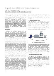
Measurement system [2, 3] for comparison of spectral<br />
responsivity of silicon detectors is shown in Figure 1.<br />
Figure 1. System of spectral comparisons. SISFRMS, light<br />
source; SFRMS, measurement station; RD, monitor<br />
detector; PN, translation stage.<br />
System is based on double monochromator, halogen<br />
light source with 3 mW optical power at 550 nm. Beam<br />
divergence (full angle) is f/6, and spot size at focal point of<br />
the system is approximately 4 mm with bandwidth of 4 nm.<br />
Three detectors (Hammatsu S1337 1010BQ) were<br />
calibrated at the end of year 2003 in BNM-INM.<br />
Calibrations were made in spectral range from 300 nm to<br />
1000 nm at 23 different wavelengths. Bandwidth was 3 nm,<br />
and spot size ≈5 nm [4].<br />
Method of comparison [5], is based on measurement<br />
equation<br />
N ( λ)<br />
G<br />
S ( λ)<br />
x 0<br />
x = 0 ( )<br />
0 ( ⋅ ⋅ S λ , (1)<br />
N λ)<br />
G x<br />
where: Sx(l), So(l) – spectral responsivity of the test and<br />
standard detector; Nx(l), No(l) – ratios of the signals from<br />
test/standard and compensation detector; Gx, Go –<br />
transimedance amplifier gain for two channels (for test and<br />
standard detector signal measurements).<br />
Detectors are automatically exchanged in the path of<br />
the light beam. Signal from main and compensation<br />
detectors are measured simultaneously, ten times each<br />
detector. Correction of dark current is applied. Signal from<br />
detector is measured with transimpendans amplifier and<br />
digital voltmeter with scanner. Transimpedance amplifier is<br />
calibrated by means of low current source calibrator and<br />
digital voltmeter. Measurement uncertainty of the method<br />
of comparison is evaluated and given in table 1.<br />
Table 1. Uncertainty budget.<br />
Uncertainty<br />
component<br />
Uncertainty<br />
(Тype А)<br />
u(Nx) 2 ×10 -4<br />
u(No) 2 ×10 -4<br />
Uncertainty<br />
(Тype B)<br />
u(Gx) 2,5×10 -4<br />
u(Go) 2,5×10 -4<br />
DVM uncertainty 2 ×10 -4<br />
beam-divergence<br />
Nonuniformity of<br />
detectors<br />
negligible<br />
not analized<br />
Nonlinearity 2 ×10 -4<br />
Wavelength accuracy 0,2 × 10 -4<br />
Bandwith efect<br />
Stray light<br />
Standard uncertainty<br />
(1σ)<br />
Combined standard<br />
uncertainty (1σ)<br />
negligible<br />
negligible<br />
2,8 ×10 -4 4,5 ×10 -4<br />
5,3 ×10 -4<br />
Proceedings NEWRAD, 17-19 October 2005, Davos, Switzerland 87


