

Here - PMOD/WRC
Here - PMOD/WRC
Here - PMOD/WRC

Create successful ePaper yourself
Turn your PDF publications into a flip-book with our unique Google optimized e-Paper software.
Correcting for bandwidth effects in monochromator measurements<br />
Emma R. Woolliams, Maurice G. Cox, Peter M. Harris, Heather M. Pegrum<br />
National Physical Laboratory, Hampton Road, Teddington, TW11 0LW, UK<br />
Abstract. In radiometric calibrations of detectors and sources it<br />
is common to use a monochromator-based system to compare the<br />
spectral response of an unknown detector with that of a known<br />
detector or the spectral irradiance of an unknown source with that<br />
of a known source. It is often assumed that this calibration can be<br />
considered to correspond to the central wavelength of the<br />
monochromator bandwidth. This paper considers when such an<br />
assumption is valid and how a correction can be made to convert<br />
integrated measurements into point values. It includes<br />
experimental verification of the methods described.<br />
Introduction<br />
The bandpass of monochromators can cause significant<br />
errors when calibrating sources or detectors that change<br />
rapidly with wavelength, particularly when the calibration<br />
is performed relative to a source or detector that has a very<br />
different spectral response [1]. Methods for correcting this<br />
for the case of a perfectly triangular slit [2,3] and for an<br />
arbitrary bandpass function [4] have been previously<br />
described.<br />
This paper describes a method for correcting the<br />
measured data to obtain an estimate of the result that<br />
would have been obtained for an infinitely narrow<br />
bandpass. The method makes no assumptions about the<br />
shape of the bandpass function, nor does it require the<br />
measured data to be modelled. The method applies for<br />
arbitrary measurement spacings that may be greater or less<br />
than the bandwidth of the monochromator. It does however<br />
assume that the function representing the measured values<br />
is continuously differentiable with respect to wavelength to<br />
a degree appropriate to the spectral shape of interest.<br />
The technique can be applied to any spectrally varying<br />
quantity measured using a monochromator. However, this<br />
paper considers the special case of the calibration of a<br />
deuterium lamp with respect to a blackbody source in the<br />
UV spectral region. Since the spectral irradiance of the<br />
deuterium lamp rapidly decreases with wavelength, while<br />
the blackbody’s spectral irradiance rapidly increases, this<br />
represents a “worst case scenario” and as such<br />
experimental results could be obtained showing noticeable<br />
differences between a wide and narrow bandwidth. Such<br />
differences have been corrected using the method<br />
described here.<br />
Measurement equation<br />
The signal of a PMT detector on the exit port of a<br />
double monochromator was recorded first when a<br />
blackbody of known temperature illuminated a diffuser on<br />
the input port of the monochromator and then again when<br />
a deuterium lamp illuminated the same diffuser.<br />
The signal obtained when using the blackbody is given<br />
by<br />
λ+<br />
1<br />
V ( λ ) = πg∫<br />
L ( λ, T) R( λ) S( λ)<br />
dλ (1)<br />
BB 0 BB<br />
λ−1<br />
where V BB<br />
( λ0<br />
) is the measured signal, g a geometric<br />
constant, L ( λ , T)<br />
the radiance of the blackbody, R( λ )<br />
BB<br />
the detector responsivity and S( λ ) the bandpass function<br />
of the monochromator. Similarly, the signal obtained when<br />
measuring the lamp is given by<br />
λ+<br />
1<br />
V ( λ ) = A∫<br />
E ( λ) R( λ) S( λ)<br />
dλ (2)<br />
lamp 0 lamp<br />
λ−1<br />
where A is a geometric constant and E lamp<br />
( λ)<br />
is the<br />
irradiance of the lamp.<br />
If the bandpass function of the monochromator were<br />
infinitely narrow, the ‘perfect’ measured signals would be<br />
and<br />
V ( λ ) = πgL ( λ , T) R( λ )<br />
(3)<br />
BB 0 BB 0 0<br />
V ( λ ) = AE ( λ ) R ( λ ).<br />
(4)<br />
lamp 0 lamp 0 0<br />
Without the integrations, the irradiance of the lamp can<br />
easily be determined by dividing the signal obtained using<br />
the lamp by that using the blackbody. It is important to<br />
understand whether the ratio for real signals is a close<br />
approximation to that for ‘perfect’ signals, i.e. whether,<br />
V V ≈ V V , and the extent to which it is<br />
lamp BB lamp BB<br />
possible to estimate the ‘perfect’ signals given the real<br />
signals.<br />
Triangular bandpass function<br />
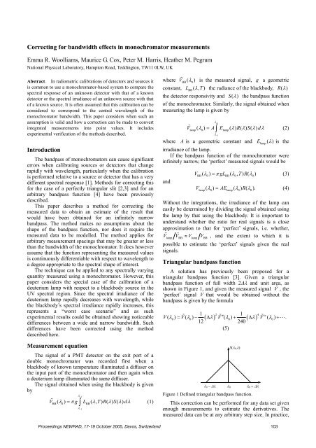
A solution has previously been proposed for a<br />
triangular bandpass function [3]. Given a triangular<br />
bandpass function of full width 2∆λ and unit area, as<br />
shown in Figure 1, and given the measured signal V , the<br />
‘perfect’ signal V that would be obtained without the<br />
bandpass is given by the formula<br />
1 2 1 4 iv<br />
V( λ0) = V( λ0) − ( ∆ λ) V′′<br />
( λ0) + ( ∆ λ)<br />
V ( λ0)<br />
+ .<br />
12 240<br />
(5)<br />
S(λ 0,λ)<br />
λ 0 − ∆λ λ 0 λ 0 + ∆λ<br />
Figure 1 Defined triangular bandpass function.<br />
This correction can be performed for any data set given<br />
enough measurements to estimate the derivatives. The<br />
measured data can be at any arbitrary step size. In practice,<br />
Proceedings NEWRAD, 17-19 October 2005, Davos, Switzerland 103


