

NIST Reference Cryogenic Radiometer Designed for ... - PMOD/WRC
NIST Reference Cryogenic Radiometer Designed for ... - PMOD/WRC
NIST Reference Cryogenic Radiometer Designed for ... - PMOD/WRC

Create successful ePaper yourself
Turn your PDF publications into a flip-book with our unique Google optimized e-Paper software.
<strong>NIST</strong> <strong>Reference</strong> <strong>Cryogenic</strong> <strong>Radiometer</strong> <strong>Designed</strong> <strong>for</strong> Versatile Per<strong>for</strong>mance<br />
J. Houston, and J. Rice<br />
National Institute of Standards and Technology, Gaithersburg, MD, USA<br />
Abstract. We describe the unique design concept of<br />
modularity and versatility in the construction of a new<br />
cryogenic radiometer developed at <strong>NIST</strong>. We address the<br />
benefits of the modular design in the construction and<br />
development and discuss some of the device<br />
characterizations and results of a cryogenic radiometer<br />
intercomparison.<br />
Introduction<br />
<strong>Cryogenic</strong> electrical substitution radiometers<br />
presently provide the basis <strong>for</strong> optical measurements in<br />
most national measurement institutes. The National<br />
Institute of Standards and Technology (<strong>NIST</strong>) required a<br />
new cryogenic radiometer that would provide the lowest<br />
possible uncertainty and yet would not become quickly<br />
obsolete. The new radiometer needed to have the<br />
versatility to grow with <strong>NIST</strong>’s needs, to embrace new<br />
technologies, and most especially still be able to provide<br />
laser power measurements with uncertainties of 0.01% or<br />
better over a range of power levels from μW to mW.<br />
Additionally, the radiometer needed to have an improved<br />
thermal per<strong>for</strong>mance and the ability to calibrate a variety<br />
of different optical detectors.<br />
Design<br />
The cryogenic radiometer that was designed and<br />
built at <strong>NIST</strong> is called the Primary Optical Watt<br />
<strong>Radiometer</strong> (POWR), previously known as HACR 2.<br />
POWR has replaced the previous High Accuracy<br />
<strong>Cryogenic</strong> <strong>Radiometer</strong> (HACR). While POWR measures<br />
optical power responsivity of detectors using lasers, the<br />
unique element of the <strong>NIST</strong> design is the concept of<br />
modularity. The radiometer can be divided into three<br />
main sections: the cryostat, the detector module that<br />
consists of the receiver cavity, heat sink, and thermal<br />
anchor, and finally the optics section. Each of these three<br />
components has design elements that contribute to<br />
POWR’s versatility. In the cryostat itself the base of the<br />
helium reservoir is a 381 mm diameter plate, called the<br />
cold plate, that contains a series of threaded holes. The<br />
critical experimental elements mount and are thermally<br />
anchored to the cold plate and are easily removed or<br />
replaced. A series of wiring paths that support the<br />
different types of four-wire heaters and thermometry and<br />
two-wire thermometry are connectorized inside the<br />
radiometer <strong>for</strong> ease of removal. One final element in the<br />
actual cryostat design is that it can be operated at two<br />
different temperatures, at 4.2 K <strong>for</strong> most measurements<br />
and at 2 K to reduce the thermal noise in the measurement<br />
of significantly lower optical powers.<br />
The detector module design is critical in that the<br />
goal was to achieve laser power measurements with 0.01%<br />
uncertainty at the microwatt and milliwatt levels and yet<br />
achieve the modularity to exchange receiver cavities. The<br />
detector module design is comprised of four main<br />
elements: the cold block, the thermal anchor, the heat sink,<br />
and the receiver cavity. The receiver cavity and the<br />
thermal anchor were specifically designed to provide the<br />
expected radiometric per<strong>for</strong>mance of POWR, the ability to<br />
measure μW to mW optical power with 0.01%<br />
uncertainties or better. The heat sink design includes a<br />
place to mount the thermal anchor and a 20 mm diameter<br />
receiver cavity combination, and a limiting entrance<br />
aperture. Heaters and thermometers on the heat sink<br />
regulate its temperature to reduce the noise and uncertainty<br />
in the receiver cavity’s measurements. The receiver<br />
cavity/heat sink module then mounts into the cold block.<br />
The main purpose of the cold block is to provide a helium<br />
temperature background that surrounds the receiver cavity.<br />
The cold block is the part of the detector module that<br />
attaches to the cold plate and is thermally anchored to the<br />
liquid helium reservoir.<br />
The front optics section includes the window<br />
section. Besides the Brewster angle window, this front<br />
optics section design provides the opportunity to measure<br />
the window transmittance in-situ. Attached between the<br />
window and the cryostat is a large, five-way cross. This<br />
cross is the location <strong>for</strong> a trap detector to be inserted to<br />
measure the transmittance of an installed window.<br />
Construction<br />
The cryostat is designed and tested <strong>for</strong> improved<br />
thermal and mechanical per<strong>for</strong>mance. The helium<br />
reservoir holds almost 100 L of liquid helium to provide a<br />
measured hold time of 14 days <strong>for</strong> normal operation. An<br />
annular reservoir of liquid nitrogen surrounds the helium<br />
reservoir <strong>for</strong> thermal insulation. The base of the helium<br />
reservoir is 304 stainless steel with helicoils <strong>for</strong> longterm<br />
mechanical per<strong>for</strong>mance (Figure 1). The wiring <strong>for</strong> the<br />
thermometry is phosphor bronze.<br />
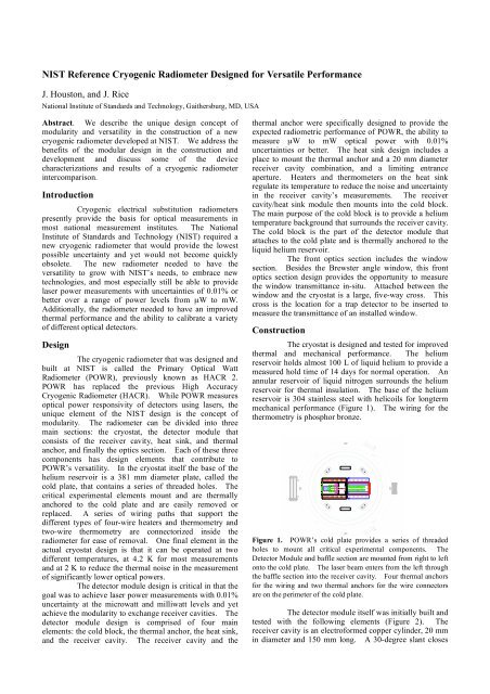
Figure 1. POWR’s cold plate provides a series of threaded<br />
holes to mount all critical experimental components. The<br />
Detector Module and baffle section are mounted from right to left<br />
onto the cold plate. The laser beam enters from the left through<br />
the baffle section into the receiver cavity. Four thermal anchors<br />
<strong>for</strong> the wiring and two thermal anchors <strong>for</strong> the wire connectors<br />
are on the perimeter of the cold plate.<br />
The detector module itself was initially built and<br />
tested with the following elements (Figure 2). The<br />
receiver cavity is an electro<strong>for</strong>med copper cylinder, 20 mm<br />
in diameter and 150 mm long. A 30-degree slant closes
off the back end of the cavity. The cavity is coated with a<br />
specular black paint. One heater is noninductivally<br />
wrapped on the closed end of the cavity, with another two<br />
chip heaters attached to the back slant. The germanium<br />
resistance thermometer is located on the cylinder barrel.<br />
All wiring from the detector module ends in connectors to<br />
provide easy detachment. A Kapton thermal anchor<br />
attaches the receiver cavity to the heat sink. Both the heat<br />
sink and the cold block are made of OFHC copper that is<br />
plated first with nickel and then gold. All surfaces are<br />
highly polished and reflective to reduce any radiative<br />
effects.<br />
Figure 2. The Detector Module is on the right half with the<br />
receiving cavity mounted onto the heat sink and surrounded by<br />
the cold block. On the left side is the baffle section with the off<br />
axis parabolic mirror and silicon photodiode combination.<br />
While the majority of the detector section itself<br />
remained unchanged, the receiver cavity and some<br />
thermometry evolved until POWR achieved the desired<br />
per<strong>for</strong>mance. The receiver cavity evolved until the<br />
per<strong>for</strong>mance was achieved in Detector Module 3.<br />
Additionally the wiring was changed to provide the<br />
capability <strong>for</strong> a feed-<strong>for</strong>ward temperature control loop<br />
algorithm.<br />
One element designed into the measurement is<br />
the determination of the light scatter magnitude. This<br />
was achieved by placing a baffle section attached to the<br />
cold block located directly in front of the detector module,<br />
and additional baffles along the interior optical path. The<br />
baffle section collects the scattered radiation with an off<br />
axis parabolic mirror that surrounds the laser beam and<br />
reflects the scattered radiation into a silicon photodiode<br />
<strong>for</strong> measurement.<br />
The evolving detector module demonstrates the<br />
benefits of the modular design. While the construction<br />
and wiring of each detector module required days of work,<br />
the actual exchange of detector modules in the cryostat<br />
itself took less than one day. A connectorized detector<br />
module was easily replaced in the cryostat.<br />
Measurements<br />
The detector modules after being painted and<br />
built were measured outside the cryostat <strong>for</strong> reflectance<br />
(from which absorptance is inferred) at three different<br />
wavelengths. The measurements were done against <strong>NIST</strong><br />
PTFE reflectance standards. The final cavity had<br />
absorptances of 0.999995 at 633 nm. Because the<br />
radiometer is versatile, the detector module can easily be<br />
removed and tested over time to see if the paint and<br />
absorptance is stable.<br />
Once Detector Module 3 was installed into the<br />
cryostat two types of measurements commenced, first the<br />
characterization of the electrical to optical equivalence and<br />
second the calibration of traps. A full discussion of<br />
POWRs characterization is to be discussed in a future<br />
paper. The calibration of the traps was per<strong>for</strong>med in two<br />
different configurations, one with the traps on a separate<br />
translation stage in front of the window, and a second with<br />
the traps in the optical plane of the receiver cavity on the<br />
translation stage that moves the radiometer itself. In the<br />
end the second setup was used. The same traps measured<br />
by POWR were measured by other cryogenic radiometers<br />
at <strong>NIST</strong> and the calibrations agreed within 0.01% to 0.02%<br />
which is well within the three radiometers uncertainties<br />
(Table 1). A full discussion of this intercomparison will<br />
be published later.<br />
Table 1. Results of a comparison of three cryogenic<br />
radiometers measuring trap detector, presented in terms of<br />
the difference from the POWR-measured responsivity of a<br />
silicon photodiode trap detector.<br />
<strong>Cryogenic</strong> 488 nm 514 nm 633 nm<br />
radiometer<br />
L1 ACR -0.021% -0.002% -0.011%<br />
LOCR -0.005% 0.020% 0.001%<br />
The radiometer Brewster-angle window was<br />
measured in-situ, but not in vacuum. The Brewster-angle<br />
window was optimized <strong>for</strong> 633 nm and maintained in that<br />
alignment <strong>for</strong> the calibrations. The transmittances at each<br />
wavelength were measured be<strong>for</strong>e and after the trap<br />
calibrations. For the window transmittance measurement<br />
the trap was inserted inside the five way cross and aligned<br />
to the laser beam. The trap was removed <strong>for</strong> POWRs<br />
calibration cycles. A typical window transmittance was<br />
0.999921 with an uncertainty of .0012% at 633 nm.<br />
Conclusion<br />
A new <strong>NIST</strong> reference cryogenic radiometer,<br />
POWR, has been developed. The goal in the<br />
development of the POWR was to have the versatility in<br />
design so that detector modules could be exchanged while<br />
providing optical power measurements at uncertainties of<br />
0.01% or better. Final characterization measurements on<br />
Detector Module 3 (Rice, et al.) are soon to be completed,<br />
but the exchanging of the first three detector modules and<br />
the per<strong>for</strong>mance of the third module shows that POWR has<br />
achieved this goal. In the future, as technology changes<br />
or there are special requests <strong>for</strong> measurements at different<br />
power levels or wavelengths, POWR will be able to meet<br />
the needs.<br />
Acknowledgements. We would like to thank Steven<br />
Lorentz and Joe O’Connell <strong>for</strong> their contributions in the<br />
construction of POWR. Responsivity measurements from<br />
the L1 ACR were provided by Steve Brown and Keith<br />
Lykke, and <strong>for</strong> the LOCR by David Livigni. We would<br />
like to thank Albert C. Parr, Chief of the Optical<br />
Technology Division at <strong>NIST</strong>, <strong>for</strong> his continued support of<br />
this project.


