TDA8510J - Unitrel
TDA8510J - Unitrel
TDA8510J - Unitrel

Create successful ePaper yourself
Turn your PDF publications into a flip-book with our unique Google optimized e-Paper software.
INTEGRATED CIRCUITS<br />
DATA SHEET<br />
<strong>TDA8510J</strong><br />
26 W BTL and 2 × 13 W SE power<br />
amplifiers<br />
Preliminary specification<br />
Supersedes data of 1999 Jun 14<br />
File under Integrated Circuits, IC01<br />
1999 Dec 14
Philips Semiconductors<br />
26 W BTL and 2 × 13 W SE power<br />
amplifiers<br />
Preliminary specification<br />
<strong>TDA8510J</strong><br />
FEATURES<br />
• Requires very few external components<br />
• High output power<br />
• Low output offset voltage (BTL channel)<br />
• Fixed gain<br />
• Diagnostic facility (distortion, short-circuit and<br />
temperature detection)<br />
• Good ripple rejection<br />
• Mode select switch (operating, mute and standby)<br />
• AC and DC short-circuit safe to ground and to V P<br />
• Low power dissipation in any short-circuit condition<br />
• Thermally protected<br />
• Reverse polarity safe<br />
• Electrostatic discharge protection<br />
• No switch-on/switch-off plop<br />
• Flexible leads<br />
• Low thermal resistance<br />
• Identical inputs (inverting and non-inverting).<br />
GENERAL DESCRIPTION<br />
The <strong>TDA8510J</strong> is an integrated class-B output amplifier in<br />
a 17-lead single-in-line (SIL) power package. It contains a<br />
26 W Bridge-Tied Load (BTL) amplifier and 2 × 13 W<br />
Single-Ended (SE) amplifiers.<br />
The device is primarily developed for multi-media<br />
applications and active speaker systems (stereo with<br />
subwoofer).<br />
QUICK REFERENCE DATA<br />
SYMBOL PARAMETER CONDITIONS MIN. TYP. MAX. UNIT<br />
General<br />
V P supply voltage 6 15 18 V<br />
I ORM repetitive peak output current − − 4 A<br />
I q(tot) total quiescent current − 80 − mA<br />
I stb standby current − 0.1 100 µA<br />
BTL channel<br />
P o output power R L =4Ω; THD = 10% − 26 − W<br />
SVRR supply voltage ripple rejection 46 − − dB<br />
V n(o) noise output voltage R s =0Ω − 70 − µV<br />
⎪Z i ⎪ input impedance 25 − − kΩ<br />
⎪∆V OO ⎪ DC output offset voltage − − 150 mV<br />
Single-ended channels<br />
P o output power THD = 10%<br />
R L =4Ω − 7 − W<br />
R L =2Ω − 13 − W<br />
SVRR supply voltage ripple rejection 46 − − dB<br />
V n(o) noise output voltage R s =0Ω − 50 − µV<br />
⎪Z i ⎪ input impedance 50 − − kΩ<br />
ORDERING INFORMATION<br />
TYPE<br />
PACKAGE<br />
NUMBER NAME DESCRIPTION VERSION<br />
<strong>TDA8510J</strong> DBS17P plastic DIL-bent-SIL power package; 17 leads (lead length 12 mm) SOT243-1<br />
1999 Dec 14 2
Philips Semiconductors<br />
26 W BTL and 2 × 13 W SE power<br />
amplifiers<br />
Preliminary specification<br />
<strong>TDA8510J</strong><br />
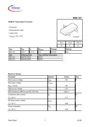
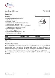
BLOCK DIAGRAM<br />
non-inverting<br />
input 1<br />
non-inverting<br />
input 2<br />
3<br />
1<br />
60<br />
kΩ<br />
2<br />
kΩ<br />
60<br />
kΩ<br />
2<br />
kΩ<br />
V P1 V P2<br />
5 13<br />
mute switch C m<br />
<strong>TDA8510J</strong><br />
VA<br />
6<br />
18 kΩ<br />
power stage<br />
mute switch C m<br />
VA<br />
8<br />
18 kΩ<br />
power stage<br />
V P<br />
output 1<br />
output 2<br />
standby<br />
switch<br />
VA<br />
15 kΩ<br />
PROTECTIONS<br />
thermal<br />
short-circuit<br />
standby<br />
reference<br />
voltage<br />
mute<br />
switch<br />
14<br />
mode<br />
select<br />
switch<br />
supply voltage<br />
ripple rejection<br />
4<br />
x1<br />
15 kΩ<br />
mute<br />
reference<br />
voltage<br />
16<br />
diagnostic<br />
output<br />
inverting<br />
input 3<br />
15<br />
60<br />
kΩ<br />
VA<br />
mute switch<br />
C m<br />
10<br />
output 3<br />
2<br />
kΩ<br />
18 kΩ<br />
power stage<br />
non-inverting<br />
input 4<br />
17<br />
60<br />
kΩ<br />
VA<br />
mute switch<br />
C m<br />
12<br />
output 4<br />
2<br />
kΩ<br />
ground<br />
(signal)<br />
input<br />
reference<br />
voltage<br />
18 kΩ<br />
2 9<br />
7 11<br />
not connected<br />
GND1<br />
GND2<br />
power stage<br />
power ground (substrate)<br />
MGL428<br />
Fig.1 Block diagram.<br />
1999 Dec 14 3
Philips Semiconductors<br />
26 W BTL and 2 × 13 W SE power<br />
amplifiers<br />
Preliminary specification<br />
<strong>TDA8510J</strong><br />
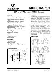
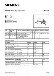
PINNING<br />
SYMBOL PIN DESCRIPTION<br />
−INV1 1 non-inverting input 1<br />
SGND 2 signal ground<br />
−INV1<br />
1<br />
−INV2 3 non-inverting input 2<br />
SGND<br />
2<br />
RR 4 supply voltage ripple rejection<br />
V P1 5 supply voltage 1<br />
OUT1 6 output 1<br />
GND1 7 power ground 1<br />
OUT2 8 output 2<br />
n.c. 9 not connected<br />
OUT3 10 output 3<br />
GND2 11 power ground 2<br />
OUT4 12 output 4<br />
V P2 13 supply voltage 2<br />
MODE 14 mode select switch input<br />
INV3 15 inverting input 3<br />
V DIAG 16 diagnostic output<br />
−INV4 17 non-inverting input 4<br />
−INV2<br />
RR<br />
V P1<br />
OUT1<br />
GND1<br />
OUT2<br />
n.c.<br />
OUT3<br />
GND2<br />
OUT4<br />
V P2<br />
MODE<br />
INV3<br />
3<br />
4<br />
5<br />
6<br />
7<br />
8<br />
9<br />
10<br />
11<br />
12<br />
13<br />
14<br />
15<br />
<strong>TDA8510J</strong><br />
V DIAG<br />
16<br />
−INV4<br />
17<br />
MGL427<br />
Fig.2 Pin configuration.<br />
1999 Dec 14 4
Philips Semiconductors<br />
26 W BTL and 2 × 13 W SE power<br />
amplifiers<br />
Preliminary specification<br />
<strong>TDA8510J</strong><br />
FUNCTIONAL DESCRIPTION<br />
The <strong>TDA8510J</strong> contains four identical amplifiers and can<br />
be used for two Single-Ended (SE) channels (fixed gain<br />
20 dB) and one Bridge-Tied Load (BTL) channel (fixed<br />
gain 26 dB). Special features of the device are:<br />
During this short-circuit condition, pin 16 is LOW for 20 ms<br />
and HIGH for 50 µs (see Fig.5).<br />
The power dissipation in any short-circuit condition is very<br />
low.<br />
Mode select switch (pin 14)<br />
• Low standby current (
Philips Semiconductors<br />
26 W BTL and 2 × 13 W SE power<br />
amplifiers<br />
Preliminary specification<br />
<strong>TDA8510J</strong><br />
handbook, full pagewidthcurrent<br />
in<br />
output<br />
stage<br />
MGL214<br />
V16<br />
short-circuit over the load<br />
20 ms<br />
t<br />
V P<br />
50 µs<br />
t<br />
Fig.5 Short-circuit waveform.<br />
TEMPERATURE DETECTION<br />
When the virtual junction temperature T vj reaches 150 °C, pin 16 will be active LOW.<br />
OPEN-COLLECTOR OUTPUT<br />
Pin 16 is an open-collector output, which allows pin 16 of more devices being tied together.<br />
LIMITING VALUES<br />
In accordance with the Absolute Maximum Rating System (IEC 134).<br />
SYMBOL PARAMETER CONDITIONS MIN. MAX. UNIT<br />
V P supply voltage operating − 18 V<br />
no signal − 20 V<br />
I OSM non-repetitive peak output current − 6 A<br />
I ORM repetitive peak output current − 4 A<br />
V sc AC and DC short-circuit safe voltage − 18 V<br />
V rp reverse polarity voltage − 6 V<br />
P tot total power dissipation − 60 W<br />
T stg storage temperature −55 +150 °C<br />
T amb operating ambient temperature −40 +85 °C<br />
T vj virtual junction temperature − 150 °C<br />
THERMAL CHARACTERISTICS<br />
In accordance with IEC 747-1.<br />
SYMBOL PARAMETER CONDITIONS VALUE UNIT<br />
R th(j-a) thermal resistance from junction to ambient in free air 40 K/W<br />
R th(j-c) thermal resistance from junction to case (see Fig.6) 1.3 K/W<br />
1999 Dec 14 6
Philips Semiconductors<br />
26 W BTL and 2 × 13 W SE power<br />
amplifiers<br />
Preliminary specification<br />
<strong>TDA8510J</strong><br />
handbook, halfpage<br />
virtual junction<br />
output 1 output 2<br />
output 3 output 4<br />
3.0 K/W<br />
3.0 K/W<br />
3.0 K/W<br />
3.0 K/W<br />
0.7 K/W<br />
0.7 K/W<br />
MEA860 - 2<br />
0.2 K/W<br />
case<br />
Fig.6 Equivalent thermal resistance network.<br />
1999 Dec 14 7
Philips Semiconductors<br />
26 W BTL and 2 × 13 W SE power<br />
amplifiers<br />
Preliminary specification<br />
<strong>TDA8510J</strong><br />
DC CHARACTERISTICS<br />
V P =15V; T amb =25°C; measured in Fig.7; unless otherwise specified.<br />
SYMBOL PARAMETER CONDITIONS MIN. TYP. MAX. UNIT<br />
Supply<br />
V P supply voltage note 1 6 15 18 V<br />
I q(tot) total quiescent current − 80 160 mA<br />
V O DC output voltage − 6.9 − V<br />
⎪∆V OO ⎪ DC output offset voltage note 2 − − 150 mV<br />
Mode select switch<br />
V SW(on) switch-on voltage level 8.5 − − V<br />
MUTE CONDITION<br />
V mute mute voltage 3.3 − 6.4 V<br />
V O output voltage in mute position V I(max) =1V; f=1kHz − − 2 mV<br />
⎪∆V OO ⎪ DC output offset voltage note 2 − − 150 mV<br />
STANDBY CONDITION<br />
V stb standby voltage 0 − 2 V<br />
I stb standby current − − 100 µA<br />
I sw(on) switch-on current − 12 40 µA<br />
Diagnostic output (pin 16)<br />
V DIAG diagnostic output voltage any short-circuit or clipping − − 0.6 V<br />
Notes<br />
1. The circuit is DC adjusted at V P = 6 to 18 V and AC operating at V P = 8.5 to 18 V.<br />
2. Only for BTL channel (V 12-10 ).<br />
1999 Dec 14 8
Philips Semiconductors<br />
26 W BTL and 2 × 13 W SE power<br />
amplifiers<br />
Preliminary specification<br />
<strong>TDA8510J</strong><br />
AC CHARACTERISTICS<br />
V P = 15 V; f = 1 kHz; T amb =25°C; measure in Fig.7; unless otherwise specified.<br />
SYMBOL PARAMETER CONDITIONS MIN. TYP. MAX. UNIT<br />
BTL channel<br />
P o output power note 1<br />
THD = 0.5% 16 20 − W<br />
THD = 10% 22 26 − W<br />
THD total harmonic distortion P o =1W − 0.06 − %<br />
B power bandwidth THD = 0.5%; − 20 to − Hz<br />
P o = −1 dB; with respect to 16 W 15000<br />
f ro(l) low frequency roll-off at −1 dB; note 2 − 25 − Hz<br />
f ro(h) high frequency roll-off at −1 dB 20 − − kHz<br />
G v closed loop voltage gain 25 26 27 dB<br />
SVRR supply voltage ripple rejection note 3<br />
on 48 − − dB<br />
mute 46 − − dB<br />
standby 80 − − dB<br />
⎪Z i ⎪ input impedance 25 30 38 kΩ<br />
V n(o) noise output voltage on; R s =0Ω; note 4 − 70 − µV<br />
on; R s =10kΩ; note 4 − 100 200 µV<br />
mute; notes 4 and 5 − 60 − µV<br />
α cs channel separation R s =10kΩ 40 60 − dB<br />
DYNAMIC DISTORTION DETECTOR<br />
THD total harmonic distortion V 16 ≤ 0.6 V; no short-circuit − 10 − %<br />
1999 Dec 14 9
Philips Semiconductors<br />
26 W BTL and 2 × 13 W SE power<br />
amplifiers<br />
Preliminary specification<br />
<strong>TDA8510J</strong><br />
SYMBOL PARAMETER CONDITIONS MIN. TYP. MAX. UNIT<br />
Single-ended channels<br />
P o output power note 1<br />
THD = 0.5% 8 10 − W<br />
THD = 10% 11 13 − W<br />
R L1 =4Ω; note 1<br />
THD = 0.5% − 5.5 − W<br />
THD = 10% − 7 − W<br />
THD total harmonic distortion P o =1W − 0.06 − %<br />
f ro(l) low frequency roll-off at −1 dB; note 2 − 25 − Hz<br />
f ro(h) high frequency roll-off at −1 dB 20 − − kHz<br />
G v closed loop voltage gain 19 20 21 dB<br />
SVRR supply voltage ripple rejection note 3<br />
on 48 − − dB<br />
mute 46 − − dB<br />
standby 80 − − dB<br />
⎪Z i ⎪ input impedance 50 60 75 kΩ<br />
V n(o) noise output voltage on; R s =0Ω; note 4 − 50 − µV<br />
on; R s =10kΩ; note 4 − 70 100 µV<br />
mute; notes 4 and 5 − 50 − µV<br />
α cs channel separation R s =10kΩ 40 60 − dB<br />
⎪∆G v ⎪ channel unbalance − − 1 dB<br />
DYNAMIC DISTORTION DETECTOR<br />
THD total harmonic distortion V 16 ≤ 0.6 V; no short-circuit − 10 − %<br />
Notes<br />
1. Output power is measured directly at the output pins of the IC.<br />
2. Frequency response externally fixed.<br />
3. Ripple rejection measured at the output with a source impedance of 0 Ω, maximum ripple amplitude of 2 V (p-p) and<br />
at a frequency of between 100 Hz and 10 kHz.<br />
4. Noise measured in a bandwidth of 20 Hz to 20 kHz.<br />
5. Noise output voltage independent of R s (V i = 0 V).<br />
1999 Dec 14 10
Philips Semiconductors<br />
26 W BTL and 2 × 13 W SE power<br />
amplifiers<br />
Preliminary specification<br />
<strong>TDA8510J</strong><br />
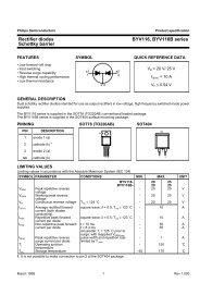
TEST AND APPLICATION INFORMATION<br />
handbook, full pagewidth<br />
mode<br />
switch<br />
10<br />
kΩ<br />
100<br />
nF<br />
V P<br />
2200<br />
µF<br />
14<br />
16 5 13<br />
input 1<br />
220 nF<br />
1<br />
<strong>TDA8510J</strong><br />
+<br />
6<br />
−<br />
1000 µF<br />
60<br />
kΩ<br />
R L1<br />
2 Ω<br />
input 2<br />
ground (signal)<br />
supply voltage<br />
ripple rejection<br />
220 nF<br />
100<br />
µF<br />
3<br />
2<br />
4<br />
1/2V P<br />
60<br />
kΩ<br />
60<br />
kΩ<br />
−<br />
+<br />
reference<br />
voltage<br />
8<br />
9<br />
1000 µF<br />
R L1<br />
2 Ω<br />
not connected<br />
15<br />
−<br />
10<br />
+<br />
inputs<br />
3 and 4<br />
470 nF<br />
17<br />
60<br />
kΩ<br />
−<br />
+<br />
12<br />
R L2<br />
4 Ω<br />
7 11<br />
MGL429<br />
power ground (substrate)<br />
Fig.7 Application diagram.<br />
1999 Dec 14 11
Philips Semiconductors<br />
26 W BTL and 2 × 13 W SE power<br />
amplifiers<br />
Preliminary specification<br />
<strong>TDA8510J</strong><br />
Mode select switch<br />
To avoid switch-on plops, it is advised to keep the amplifier<br />
in the mute mode during >100 ms (charging of the input<br />
capacitors at pins 1, 3, 15 and 17.<br />
The circuit in Fig.8 slowly ramps up the voltage at the<br />
mode select switch pin when switching on and results in<br />
fast muting when switching off.<br />
V<br />
handbook, halfpage P<br />
10 kΩ 100 Ω<br />
47 µF<br />
mode<br />
select<br />
switch<br />
100 kΩ<br />
MGA708<br />
Fig.8 Mode select switch circuitry.<br />
1999 Dec 14 12
Philips Semiconductors<br />
26 W BTL and 2 × 13 W SE power<br />
amplifiers<br />
Preliminary specification<br />
<strong>TDA8510J</strong><br />
PACKAGE OUTLINE<br />
DBS17P: plastic DIL-bent-SIL power package; 17 leads (lead length 12 mm)<br />
SOT243-1<br />
D<br />
non-concave<br />
x<br />
Dh<br />
E h<br />
view B: mounting base side<br />
d<br />
A 2<br />
B<br />
j<br />
E<br />
A<br />
L 3<br />
L<br />
Q<br />
c<br />
v M<br />
1 17<br />
Z<br />
e<br />
e1<br />
b p<br />
w M<br />
m e2<br />
0 5 10 mm<br />
scale<br />
DIMENSIONS (mm are the original dimensions)<br />
UNIT A A 2 b p c D (1) d D E (1) e e 1<br />
Z (1)<br />
h e 2 E h j L L 3 m Q v w x<br />
mm 17.0<br />
15.5<br />
4.6<br />
4.2<br />
0.75<br />
0.60<br />
0.48<br />
0.38<br />
24.0<br />
23.6<br />
20.0<br />
19.6<br />
12.2<br />
10 2.54<br />
11.8<br />
1.27<br />
5.08<br />
6<br />
3.4<br />
3.1<br />
12.4<br />
11.0<br />
2.4<br />
1.6<br />
4.3<br />
2.1<br />
1.8<br />
0.8<br />
0.4<br />
0.03<br />
2.00<br />
1.45<br />
Note<br />
1. Plastic or metal protrusions of 0.25 mm maximum per side are not included.<br />
OUTLINE<br />
VERSION<br />
REFERENCES<br />
IEC JEDEC EIAJ<br />
EUROPEAN<br />
PROJECTION<br />
ISSUE DATE<br />
SOT243-1<br />
95-03-11<br />
97-12-16<br />
1999 Dec 14 13
Philips Semiconductors<br />
26 W BTL and 2 × 13 W SE power<br />
amplifiers<br />
Preliminary specification<br />
<strong>TDA8510J</strong><br />
SOLDERING<br />
Introduction to soldering through-hole mount<br />
packages<br />
This text gives a brief insight to wave, dip and manual<br />
soldering. A more in-depth account of soldering ICs can be<br />
found in our “Data Handbook IC26; Integrated Circuit<br />
Packages” (document order number 9398 652 90011).<br />
Wave soldering is the preferred method for mounting of<br />
through-hole mount IC packages on a printed-circuit<br />
board.<br />
Soldering by dipping or by solder wave<br />
The maximum permissible temperature of the solder is<br />
260 °C; solder at this temperature must not be in contact<br />
with the joints for more than 5 seconds.<br />
The total contact time of successive solder waves must not<br />
exceed 5 seconds.<br />
The device may be mounted up to the seating plane, but<br />
the temperature of the plastic body must not exceed the<br />
specified maximum storage temperature (T stg(max) ). If the<br />
printed-circuit board has been pre-heated, forced cooling<br />
may be necessary immediately after soldering to keep the<br />
temperature within the permissible limit.<br />
Manual soldering<br />
Apply the soldering iron (24 V or less) to the lead(s) of the<br />
package, either below the seating plane or not more than<br />
2 mm above it. If the temperature of the soldering iron bit<br />
is less than 300 °C it may remain in contact for up to<br />
10 seconds. If the bit temperature is between<br />
300 and 400 °C, contact may be up to 5 seconds.<br />
Suitability of through-hole mount IC packages for dipping and wave soldering methods<br />
SOLDERING METHOD<br />
PACKAGE<br />
DIPPING<br />
DBS, DIP, HDIP, SDIP, SIL suitable suitable (1)<br />
WAVE<br />
Note<br />
1. For SDIP packages, the longitudinal axis must be parallel to the transport direction of the printed-circuit board.<br />
DEFINITIONS<br />
Data sheet status<br />
Objective specification This data sheet contains target or goal specifications for product development.<br />
Preliminary specification This data sheet contains preliminary data; supplementary data may be published later.<br />
Product specification This data sheet contains final product specifications.<br />
Limiting values<br />
Limiting values given are in accordance with the Absolute Maximum Rating System (IEC 134). Stress above one or<br />
more of the limiting values may cause permanent damage to the device. These are stress ratings only and operation<br />
of the device at these or at any other conditions above those given in the Characteristics sections of the specification<br />
is not implied. Exposure to limiting values for extended periods may affect device reliability.<br />
Application information<br />
Where application information is given, it is advisory and does not form part of the specification.<br />
LIFE SUPPORT APPLICATIONS<br />
These products are not designed for use in life support appliances, devices, or systems where malfunction of these<br />
products can reasonably be expected to result in personal injury. Philips customers using or selling these products for<br />
use in such applications do so at their own risk and agree to fully indemnify Philips for any damages resulting from such<br />
improper use or sale.<br />
1999 Dec 14 14
Philips Semiconductors<br />
26 W BTL and 2 × 13 W SE power<br />
amplifiers<br />
Preliminary specification<br />
<strong>TDA8510J</strong><br />
NOTES<br />
1999 Dec 14 15
Philips Semiconductors – a worldwide company<br />
Argentina: see South America<br />
Australia: 3 Figtree Drive, HOMEBUSH, NSW 2140,<br />
Tel. +61 2 9704 8141, Fax. +61 2 9704 8139<br />
Austria: Computerstr. 6, A-1101 WIEN, P.O. Box 213,<br />
Tel. +43 1 60 101 1248, Fax. +43 1 60 101 1210<br />
Belarus: Hotel Minsk Business Center, Bld. 3, r. 1211, Volodarski Str. 6,<br />
220050 MINSK, Tel. +375 172 20 0733, Fax. +375 172 20 0773<br />
Belgium: see The Netherlands<br />
Brazil: see South America<br />
Bulgaria: Philips Bulgaria Ltd., Energoproject, 15th floor,<br />
51 James Bourchier Blvd., 1407 SOFIA,<br />
Tel. +359 2 68 9211, Fax. +359 2 68 9102<br />
Canada: PHILIPS SEMICONDUCTORS/COMPONENTS,<br />
Tel. +1 800 234 7381, Fax. +1 800 943 0087<br />
China/Hong Kong: 501 Hong Kong Industrial Technology Centre,<br />
72 Tat Chee Avenue, Kowloon Tong, HONG KONG,<br />
Tel. +852 2319 7888, Fax. +852 2319 7700<br />
Colombia: see South America<br />
Czech Republic: see Austria<br />
Denmark: Sydhavnsgade 23, 1780 COPENHAGEN V,<br />
Tel. +45 33 29 3333, Fax. +45 33 29 3905<br />
Finland: Sinikalliontie 3, FIN-02630 ESPOO,<br />
Tel. +358 9 615 800, Fax. +358 9 6158 0920<br />
France: 51 Rue Carnot, BP317, 92156 SURESNES Cedex,<br />
Tel. +33 1 4099 6161, Fax. +33 1 4099 6427<br />
Germany: Hammerbrookstraße 69, D-20097 HAMBURG,<br />
Tel. +49 40 2353 60, Fax. +49 40 2353 6300<br />
Hungary: see Austria<br />
India: Philips INDIA Ltd, Band Box Building, 2nd floor,<br />
254-D, Dr. Annie Besant Road, Worli, MUMBAI 400 025,<br />
Tel. +91 22 493 8541, Fax. +91 22 493 0966<br />
Indonesia: PT Philips Development Corporation, Semiconductors Division,<br />
Gedung Philips, Jl. Buncit Raya Kav.99-100, JAKARTA 12510,<br />
Tel. +62 21 794 0040 ext. 2501, Fax. +62 21 794 0080<br />
Ireland: Newstead, Clonskeagh, DUBLIN 14,<br />
Tel. +353 1 7640 000, Fax. +353 1 7640 200<br />
Israel: RAPAC Electronics, 7 Kehilat Saloniki St, PO Box 18053,<br />
TEL AVIV 61180, Tel. +972 3 645 0444, Fax. +972 3 649 1007<br />
Italy: PHILIPS SEMICONDUCTORS, Via Casati, 23 - 20052 MONZA (MI),<br />
Tel. +39 039 203 6838, Fax +39 039 203 6800<br />
Japan: Philips Bldg 13-37, Kohnan 2-chome, Minato-ku,<br />
TOKYO 108-8507, Tel. +81 3 3740 5130, Fax. +81 3 3740 5057<br />
Korea: Philips House, 260-199 Itaewon-dong, Yongsan-ku, SEOUL,<br />
Tel. +82 2 709 1412, Fax. +82 2 709 1415<br />
Malaysia: No. 76 Jalan Universiti, 46200 PETALING JAYA, SELANGOR,<br />
Tel. +60 3 750 5214, Fax. +60 3 757 4880<br />
Mexico: 5900 Gateway East, Suite 200, EL PASO, TEXAS 79905,<br />
Tel. +9-5 800 234 7381, Fax +9-5 800 943 0087<br />
Middle East: see Italy<br />
Netherlands: Postbus 90050, 5600 PB EINDHOVEN, Bldg. VB,<br />
Tel. +31 40 27 82785, Fax. +31 40 27 88399<br />
New Zealand: 2 Wagener Place, C.P.O. Box 1041, AUCKLAND,<br />
Tel. +64 9 849 4160, Fax. +64 9 849 7811<br />
Norway: Box 1, Manglerud 0612, OSLO,<br />
Tel. +47 22 74 8000, Fax. +47 22 74 8341<br />
Pakistan: see Singapore<br />
Philippines: Philips Semiconductors Philippines Inc.,<br />
106 Valero St. Salcedo Village, P.O. Box 2108 MCC, MAKATI,<br />
Metro MANILA, Tel. +63 2 816 6380, Fax. +63 2 817 3474<br />
Poland: Al.Jerozolimskie 195 B, 02-222 WARSAW,<br />
Tel. +48 22 5710 000, Fax. +48 22 5710 001<br />
Portugal: see Spain<br />
Romania: see Italy<br />
Russia: Philips Russia, Ul. Usatcheva 35A, 119048 MOSCOW,<br />
Tel. +7 095 755 6918, Fax. +7 095 755 6919<br />
Singapore: Lorong 1, Toa Payoh, SINGAPORE 319762,<br />
Tel. +65 350 2538, Fax. +65 251 6500<br />
Slovakia: see Austria<br />
Slovenia: see Italy<br />
South Africa: S.A. PHILIPS Pty Ltd., 195-215 Main Road Martindale,<br />
2092 JOHANNESBURG, P.O. Box 58088 Newville 2114,<br />
Tel. +27 11 471 5401, Fax. +27 11 471 5398<br />
South America: Al. Vicente Pinzon, 173, 6th floor,<br />
04547-130 SÃO PAULO, SP, Brazil,<br />
Tel. +55 11 821 2333, Fax. +55 11 821 2382<br />
Spain: Balmes 22, 08007 BARCELONA,<br />
Tel. +34 93 301 6312, Fax. +34 93 301 4107<br />
Sweden: Kottbygatan 7, Akalla, S-16485 STOCKHOLM,<br />
Tel. +46 8 5985 2000, Fax. +46 8 5985 2745<br />
Switzerland: Allmendstrasse 140, CH-8027 ZÜRICH,<br />
Tel. +41 1 488 2741 Fax. +41 1 488 3263<br />
Taiwan: Philips Semiconductors, 6F, No. 96, Chien Kuo N. Rd., Sec. 1,<br />
TAIPEI, Taiwan Tel. +886 2 2134 2886, Fax. +886 2 2134 2874<br />
Thailand: PHILIPS ELECTRONICS (THAILAND) Ltd.,<br />
209/2 Sanpavuth-Bangna Road Prakanong, BANGKOK 10260,<br />
Tel. +66 2 745 4090, Fax. +66 2 398 0793<br />
Turkey: Yukari Dudullu, Org. San. Blg., 2.Cad. Nr. 28 81260 Umraniye,<br />
ISTANBUL, Tel. +90 216 522 1500, Fax. +90 216 522 1813<br />
Ukraine: PHILIPS UKRAINE, 4 Patrice Lumumba str., Building B, Floor 7,<br />
252042 KIEV, Tel. +380 44 264 2776, Fax. +380 44 268 0461<br />
United Kingdom: Philips Semiconductors Ltd., 276 Bath Road, Hayes,<br />
MIDDLESEX UB3 5BX, Tel. +44 208 730 5000, Fax. +44 208 754 8421<br />
United States: 811 East Arques Avenue, SUNNYVALE, CA 94088-3409,<br />
Tel. +1 800 234 7381, Fax. +1 800 943 0087<br />
Uruguay: see South America<br />
Vietnam: see Singapore<br />
Yugoslavia: PHILIPS, Trg N. Pasica 5/v, 11000 BEOGRAD,<br />
Tel. +381 11 62 5344, Fax.+381 11 63 5777<br />
For all other countries apply to: Philips Semiconductors,<br />
International Marketing & Sales Communications, Building BE-p, P.O. Box 218,<br />
5600 MD EINDHOVEN, The Netherlands, Fax. +31 40 27 24825<br />
Internet: http://www.semiconductors.philips.com<br />
© Philips Electronics N.V. 1999 SCA68<br />
All rights are reserved. Reproduction in whole or in part is prohibited without the prior written consent of the copyright owner.<br />
The information presented in this document does not form part of any quotation or contract, is believed to be accurate and reliable and may be changed<br />
without notice. No liability will be accepted by the publisher for any consequence of its use. Publication thereof does not convey nor imply any license<br />
under patent- or other industrial or intellectual property rights.<br />
Printed in The Netherlands 545002/03/pp16 Date of release: 1999 Dec 14 Document order number: 9397 750 06653