YUV 8-bit video low-power analog-to-digital interface - Unitrel
YUV 8-bit video low-power analog-to-digital interface - Unitrel
YUV 8-bit video low-power analog-to-digital interface - Unitrel

Create successful ePaper yourself
Turn your PDF publications into a flip-book with our unique Google optimized e-Paper software.
INTEGRATED CIRCUITS<br />
DATA SHEET<br />
TDA8755<br />
<strong>YUV</strong> 8-<strong>bit</strong> <strong>video</strong> <strong>low</strong>-<strong>power</strong><br />
<strong>analog</strong>-<strong>to</strong>-<strong>digital</strong> <strong>interface</strong><br />
Product specification<br />
Supersedes data of June 1994<br />
File under Integrated Circuits, IC02<br />
1995 Mar 09<br />
Philips Semiconduc<strong>to</strong>rs
Philips Semiconduc<strong>to</strong>rs<br />
<strong>YUV</strong> 8-<strong>bit</strong> <strong>video</strong> <strong>low</strong>-<strong>power</strong><br />
<strong>analog</strong>-<strong>to</strong>-<strong>digital</strong> <strong>interface</strong><br />
Product specification<br />
TDA8755<br />
FEATURES<br />
• 8-<strong>bit</strong> resolution<br />
• Sampling rate up <strong>to</strong> 20 MHz<br />
• TTL compatible <strong>digital</strong> inputs<br />
• 3-state TTL outputs<br />
• U, V two's complement outputs<br />
• Y binary output<br />
• Power dissipation of 550 mW (typical)<br />
• Low <strong>analog</strong> input capacitance, no buffer amplifier<br />
required<br />
• High signal-<strong>to</strong>-noise ratio over a large <strong>analog</strong> input<br />
frequency range<br />
• Track-and-hold included<br />
• Clamp functions included<br />
• UV multiplexed ADC<br />
• 4:1:1 output data encoder<br />
• Stable voltage regula<strong>to</strong>r included.<br />
APPLICATIONS<br />
• High speed <strong>analog</strong>-<strong>to</strong>-<strong>digital</strong> conversion for <strong>video</strong> signal<br />
digitizing<br />
• 100 Hz improved definition TV (IDTV).<br />
GENERAL DESCRIPTION<br />
The TDA8755 is a bipolar 8-<strong>bit</strong> <strong>video</strong> <strong>low</strong>-<strong>power</strong><br />
<strong>analog</strong>-<strong>to</strong>-<strong>digital</strong> conversion (ADC) <strong>interface</strong> for <strong>YUV</strong><br />
signals. The device converts the <strong>YUV</strong> <strong>analog</strong> input signal<br />
in<strong>to</strong> 8-<strong>bit</strong> coded <strong>digital</strong> words in a 4 : 1 : 1 format at a<br />
sampling rate of 20 MHz. The U/V signals are converted in<br />
a multiplexed manner. All <strong>analog</strong> signal inputs are <strong>digital</strong>ly<br />
clamped and a fast precharge is provided for start-up.<br />
All <strong>digital</strong> inputs and outputs are TTL compatible. Frame<br />
synchronization is supported in a multiplexed manner.<br />
QUICK REFERENCE DATA<br />
SYMBOL PARAMETER CONDITIONS MIN. TYP. MAX. UNIT<br />
V CCA <strong>analog</strong> supply voltage 4.75 5.0 5.25 V<br />
V CCD <strong>digital</strong> supply voltage 4.75 5.0 5.25 V<br />
V CCO output stages supply voltage 4.75 5.0 5.25 V<br />
I CCA <strong>analog</strong> supply current − 46 55 mA<br />
I CCD <strong>digital</strong> supply current − 55 66 mA<br />
I CCO output stages supply current − 9 12 mA<br />
INL DC integral non-linearity f clk = 2 MHz − ±0.4 ±1 LSB<br />
DNL DC differential non-linearity f clk = 2 MHz − ±0.3 ±0.5 LSB<br />
EB effective <strong>bit</strong>s − 7.1 − <strong>bit</strong>s<br />
f clk(max) maximum clock frequency 20 − − MHz<br />
P <strong>to</strong>t <strong>to</strong>tal <strong>power</strong> dissipation − 550 700 mW<br />
ORDERING INFORMATION<br />
TYPE NUMBER<br />
PACKAGE<br />
PINS PIN POSITION MATERIAL CODE<br />
TDA8755T 32 SO32L plastic SOT287-1<br />
1995 Mar 09 2
Philips Semiconduc<strong>to</strong>rs<br />
<strong>YUV</strong> 8-<strong>bit</strong> <strong>video</strong> <strong>low</strong>-<strong>power</strong><br />
<strong>analog</strong>-<strong>to</strong>-<strong>digital</strong> <strong>interface</strong><br />
Product specification<br />
TDA8755<br />
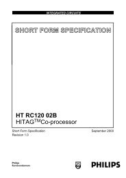
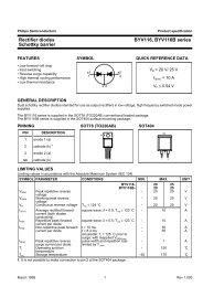
BLOCK DIAGRAM<br />
V CCA V CCD V CCO AGND DGND SDN n.c. REG1 REG2 REG3<br />
6 32 23 10 18 8 1<br />
2 4 13<br />
SUPPLY AND REFERENCE<br />
VOLTAGE REGULATOR<br />
TRACK 8-BIT 8 8-BIT 8 TTL 24<br />
AND ADC<br />
PIPELINE I / O<br />
CLAMP<br />
HOLD<br />
31<br />
Y<br />
CLAMP<br />
COMPARATOR<br />
LOGIC<br />
16<br />
16<br />
14<br />
TIMING GENERATOR<br />
17<br />
TRACK<br />
AND<br />
HOLD<br />
CLAMP<br />
U<br />
8<br />
20<br />
CLAMP<br />
V<br />
DIGITAL<br />
MULTIPLEXER<br />
ANALOG<br />
MULTIPLEXER<br />
TRACK<br />
AND<br />
HOLD<br />
8-BIT<br />
ADC<br />
U AND V<br />
DATA<br />
ENCODER<br />
TTL<br />
I / O<br />
TRACK<br />
AND<br />
HOLD<br />
COMPARATOR<br />
128<br />
MLA734 - 1<br />
handbook, full pagewidth<br />
INY<br />
CLPY<br />
CLP<br />
INU<br />
CLPU<br />
CLPV<br />
INV<br />
3<br />
5<br />
15<br />
7<br />
11<br />
12<br />
9<br />
21<br />
22<br />
TDA8755<br />
Fig.1 Block diagram.<br />
8<br />
D0<br />
D7<br />
HREF<br />
CE<br />
CLK<br />
2 D'0<br />
D'1<br />
2<br />
D'2<br />
D'3<br />
Y<br />
V<br />
U<br />
1995 Mar 09 3
Philips Semiconduc<strong>to</strong>rs<br />
<strong>YUV</strong> 8-<strong>bit</strong> <strong>video</strong> <strong>low</strong>-<strong>power</strong><br />
<strong>analog</strong>-<strong>to</strong>-<strong>digital</strong> <strong>interface</strong><br />
Product specification<br />
TDA8755<br />
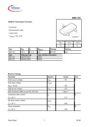
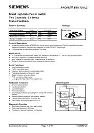
PINNING<br />
SYMBOL PIN DESCRIPTION<br />
n.c. 1 not connected<br />
REG1 2 decoupling input (internal<br />
stabilization loop decoupling)<br />
INY 3 Y <strong>analog</strong> voltage input<br />
REG2 4 decoupling input (internal<br />
stabilization loop decoupling)<br />
CLPY 5 Y clamp capaci<strong>to</strong>r connection<br />
V CCA 6 <strong>analog</strong> positive supply voltage<br />
(+5 V)<br />
INU 7 U <strong>analog</strong> voltage input<br />
SDN 8 stabilizer decoupling node and<br />
<strong>analog</strong> reference voltage (+3.35 V)<br />
INV 9 V <strong>analog</strong> voltage input<br />
AGND 10 <strong>analog</strong> ground<br />
CLPU 11 U clamp capaci<strong>to</strong>r connection<br />
CLPV 12 V clamp capaci<strong>to</strong>r connection<br />
REG3 13 decoupling input (internal<br />
stabilization loop decoupling)<br />
CE 14 chip enable input (TTL level input<br />
active LOW)<br />
CLP 15 clamp control input<br />
HREF 16 horizontal reference signal<br />
CLK 17 clock input<br />
DGND 18 <strong>digital</strong> ground<br />
D'0 19 V data output; <strong>bit</strong> 0 (n−1)<br />
D'1 20 V data output; <strong>bit</strong> 1 (n)<br />
D'2 21 U data output; <strong>bit</strong> 0 (n−1)<br />
D'3 22 U data output; <strong>bit</strong> 1 (n)<br />
V CCO 23 positive supply voltage for output<br />
stages (+5 V)<br />
D0 24 Y data output; <strong>bit</strong> 0 (LSB)<br />
D1 25 Y data output; <strong>bit</strong> 1<br />
D2 26 Y data output; <strong>bit</strong> 2<br />
D3 27 Y data output; <strong>bit</strong> 3<br />
D4 28 Y data output; <strong>bit</strong> 4<br />
D5 29 Y data output; <strong>bit</strong> 5<br />
D6 30 Y data output; <strong>bit</strong> 6<br />
D7 31 Y data output; <strong>bit</strong> 7 (MSB)<br />
V CCD 32 <strong>digital</strong> positive supply voltage (+5 V)<br />
handbook, halfpage<br />
n.c. 1<br />
32 V CCD<br />
REG1<br />
INY<br />
REG2<br />
CLPY<br />
V CCA<br />
2<br />
3<br />
4<br />
5<br />
6<br />
31<br />
30<br />
29<br />
28<br />
27<br />
D7<br />
D6<br />
D5<br />
D4<br />
D3<br />
INU 7<br />
26 D2<br />
SDN 8<br />
25 D1<br />
TDA8755<br />
INV<br />
AGND<br />
CLPU<br />
CLPV<br />
REG3<br />
CE<br />
CLP<br />
HREF<br />
9<br />
10<br />
11<br />
12<br />
13<br />
14<br />
15<br />
16<br />
24<br />
23<br />
22<br />
21<br />
20<br />
19<br />
18<br />
17<br />
D0<br />
V CCO<br />
D'3<br />
D'2<br />
D'1<br />
D'0<br />
DGND<br />
CLK<br />
MLA728 - 1<br />
Fig.2 Pin configuration.<br />
1995 Mar 09 4
Philips Semiconduc<strong>to</strong>rs<br />
<strong>YUV</strong> 8-<strong>bit</strong> <strong>video</strong> <strong>low</strong>-<strong>power</strong><br />
<strong>analog</strong>-<strong>to</strong>-<strong>digital</strong> <strong>interface</strong><br />
Product specification<br />
TDA8755<br />
LIMITING VALUES<br />
In accordance with the Absolute Maximum Rating System (IEC134).<br />
SYMBOL PARAMETER CONDITIONS MIN. MAX. UNIT<br />
V CCA <strong>analog</strong> supply voltage −0.3 +7.0 V<br />
V CCD <strong>digital</strong> supply voltage −0.3 +7.0 V<br />
V CCO output stages supply voltage −0.3 +7.0 V<br />
∆V CC supply voltage difference between V CCA and V CCD −1.0 +1.0 V<br />
supply voltage difference between V CCO and V CCD −1.0 +1.0 V<br />
supply voltage difference between V CCA and V CCO −1.0 +1.0 V<br />
V I input voltage referenced <strong>to</strong> AGND − +5.0 V<br />
V clk(p-p) AC input voltage for switching (peak-<strong>to</strong>-peak value) referenced <strong>to</strong> DGND − V CCD V<br />
I O output current − +6 mA<br />
T stg s<strong>to</strong>rage temperature −55 +150 °C<br />
T amb operating ambient temperature 0 +70 °C<br />
T j junction temperature − +150 °C<br />
HANDLING<br />
Inputs and outputs are protected against electrostatic discharges in normal handling. However, <strong>to</strong> be <strong>to</strong>tally safe, it is<br />
desirable <strong>to</strong> take normal precautions appropriate <strong>to</strong> handling integrated circuits.<br />
THERMAL CHARACTERISTICS<br />
SYMBOL PARAMETER VALUE UNIT<br />
R th j-a thermal resistance from junction <strong>to</strong> ambient in free air 70 K/W<br />
1995 Mar 09 5
Philips Semiconduc<strong>to</strong>rs<br />
<strong>YUV</strong> 8-<strong>bit</strong> <strong>video</strong> <strong>low</strong>-<strong>power</strong><br />
<strong>analog</strong>-<strong>to</strong>-<strong>digital</strong> <strong>interface</strong><br />
Product specification<br />
TDA8755<br />
CHARACTERISTICS<br />
V CCA =V 6 <strong>to</strong> V 10 = 4.75 <strong>to</strong> 5.25 V; V CCD =V 32 <strong>to</strong> V 18 = 4.75 <strong>to</strong> 5.25 V; V CCO =V 23 <strong>to</strong> V 18 = 4.75 <strong>to</strong> 5.25 V;<br />
AGND and DGND shorted <strong>to</strong>gether; V CCA <strong>to</strong> V CCD = −0.25 <strong>to</strong> +0.25 V; V CCO <strong>to</strong> V CCD = −0.25 <strong>to</strong> +0.25 V;<br />
V CCA <strong>to</strong> V CCO = −0.25 <strong>to</strong> +0.25 V; T amb = 0 <strong>to</strong> +70 °C; typical values measured at V CCA =V CCD =V CCO = 5 V and<br />
T amb =25°C; unless otherwise specified.<br />
SYMBOL PARAMETER CONDITIONS MIN. TYP. MAX. UNIT<br />
Supply<br />
V CCA <strong>analog</strong> supply voltage 4.75 5.0 5.25 V<br />
V CCD <strong>digital</strong> supply voltage 4.75 5.0 5.25 V<br />
V CCO output stages supply voltage 4.75 5.0 5.25 V<br />
I CCA <strong>analog</strong> supply current − 46 55 mA<br />
I CCD <strong>digital</strong> supply current − 55 66 mA<br />
I CCO output stages supply current − 9 12 mA<br />
Inputs<br />
CLK (PIN 17)<br />
V IL LOW level input voltage 0 − 0.8 V<br />
V IH HIGH level input voltage 2.0 − V CCD V<br />
I IL LOW level input current V clk = 0.4 V −400 − − µA<br />
I IH HIGH level input current V clk = 2.7 V − − 100 µA<br />
Z I input impedance f clk =20MHz − 4 − kΩ<br />
C I input capacitance f clk =20MHz − 4.5 − pF<br />
CE, CLP AND HREF (PINS 14 TO 16)<br />
V IL LOW level input voltage 0 − 0.8 V<br />
V IH HIGH level input voltage 2.0 − V CCD V<br />
I IL LOW level input current V clk = 0.4 V −400 − − µA<br />
I IH HIGH level input current V clk = 2.7 V − − 100 µA<br />
CLPY (PIN 5)<br />
V 5 clamp voltage for 16 output code − 3.725 − V<br />
I 5 clamp output current − ±50 − µA<br />
CLPU AND CLPV (PINS 11 AND 12)<br />
V 11, 12 clamp voltage for 128 output code − 3.30 − V<br />
I 11, 12 clamp output current − ±50 − µA<br />
INY (PIN 3)<br />
V I(p-p) input voltage, full range<br />
f i = 4.43 MHz 0.93 1.0 1.07 V<br />
(peak-<strong>to</strong>-peak value)<br />
Z I input impedance f i = 6 MHz − 30 − kΩ<br />
C I input capacitance f i = 6 MHz − 1 − pF<br />
1995 Mar 09 6
Philips Semiconduc<strong>to</strong>rs<br />
<strong>YUV</strong> 8-<strong>bit</strong> <strong>video</strong> <strong>low</strong>-<strong>power</strong><br />
<strong>analog</strong>-<strong>to</strong>-<strong>digital</strong> <strong>interface</strong><br />
Product specification<br />
TDA8755<br />
SYMBOL PARAMETER CONDITIONS MIN. TYP. MAX. UNIT<br />
INU AND INV (PINS 7 AND 9)<br />
V I(p-p) input voltage, full range<br />
f i = 1.5 MHz 0.93 1.03 1.13 V<br />
(peak-<strong>to</strong>-peak value)<br />
Z I input impedance f i = 2 MHz − 30 − kΩ<br />
C I input capacitance f i = 2 MHz − 1 − pF<br />
INPUTS ISOLATION<br />
α ct crosstalk between Y, U and V − −55 −50 dB<br />
Outputs<br />
SDN (PIN 8)<br />
V ref reference voltage − 3.32 − V<br />
V REG line regulation 4.75 V ≤ V CCA ≤ 5.25 V − 4.0 − mV<br />
I L load current −2 − − mA<br />
DIGITAL OUTPUTS D0 TO D7 AND D’0 TO D’3 (PINS 24 TO 31 AND 19 TO 22)<br />
V OL LOW level output voltage I O = 0.4 mA 0 − 0.4 V<br />
I O = 1.5 mA 0 − 0.5 V<br />
V OH HIGH level output voltage I O = −0.4 mA 2.4 − V CCD V<br />
I OZ output current in 3-state mode 0.4 V < V O
Philips Semiconduc<strong>to</strong>rs<br />
<strong>YUV</strong> 8-<strong>bit</strong> <strong>video</strong> <strong>low</strong>-<strong>power</strong><br />
<strong>analog</strong>-<strong>to</strong>-<strong>digital</strong> <strong>interface</strong><br />
Product specification<br />
TDA8755<br />
SYMBOL PARAMETER CONDITIONS MIN. TYP. MAX. UNIT<br />
Timing (f clk = 20 MHz); note 6; see Figs 3 <strong>to</strong> 7<br />
t ds sampling delay time − 1 − ns<br />
t h output hold time 7 − − ns<br />
t d output delay time − 33 42 ns<br />
t dZH 3-state output delay time enable-<strong>to</strong>-HIGH − 10 14 ns<br />
t dZL 3-state output delay time enable-<strong>to</strong>-LOW − 10 14 ns<br />
t dHZ 3-state output delay time disable-<strong>to</strong>-HIGH − 8 11 ns<br />
t dLZ 3-state output delay time disable-<strong>to</strong>-LOW − 4 6 ns<br />
t r clock rise time 3 5 − ns<br />
t f clock fall time 3 5 − ns<br />
t su HREF set-up time 7 − − ns<br />
t h HREF hold time 3 − − ns<br />
t r data output rise time − 12 − ns<br />
t f data output fall time − 16 − ns<br />
t CLP minimum time for active clamp note 7; see Fig.9 3 − − µs<br />
Notes<br />
1. Low frequency ramp signal (V I(p-p) = full-scale and 64 µs period) combined with a sinewave input voltage<br />
(V I(p-p) = 0.25 full-scale, f i = maximum permitted frequency) at the input.<br />
2. The input conditions are related as fol<strong>low</strong>s:<br />
a) Y channel: V I(p-p) = 1.0 V; f i = 4.43 MHz<br />
b) U/V channel: V I(p-p) = 1.0 V; f i = 1.5 MHz.<br />
3. Supply voltage ripple rejection:<br />
a) SVRR1 is the variation of the input voltage producing output code 127 (code 15) for supply voltage variation<br />
of 0.5 V:<br />
SVRR1 20 log ∆V I( 127)<br />
= ---------------------<br />
∆V CCA<br />
b) SVRR2 is the relative variation of the full-scale range of <strong>analog</strong> input for a supply voltage variation of 0.5 V:<br />
∆ ( V I( 0)<br />
– V I( 255)<br />
) 1<br />
SVVR2 = ------------------------------------------------ × -----------------<br />
V I( 0)<br />
– V I ( 255)<br />
∆ V CCA<br />
4. Full-scale sinewave (f i = 4.43 MHz for Y and f i = 1.5 MHz for U and V; f clk = 20 MHz).<br />
5. The number of effective <strong>bit</strong>s is measured using a 20 MHz clock frequency. This value is given for a 4.43 MHz input<br />
frequency on the Y channel (1.5 MHz on the U and V channels). This value is obtained via a Fast Fourier Transform<br />
(FFT) treatment taking 4 × T clk (clock periods) acquisition points per period. The calculation takes in<strong>to</strong> account all<br />
harmonics and noise up <strong>to</strong> half of the clock frequency (NYQUIST frequency).<br />
Conversion <strong>to</strong> signal-<strong>to</strong>-noise ratio: S/N = EB × 6.02 + 1.76 dB.<br />
6. Output data acquisition is available after the maximum delay time of t d .<br />
7. U and V output data is not valid during t CLP .<br />
1995 Mar 09 8
Philips Semiconduc<strong>to</strong>rs<br />
<strong>YUV</strong> 8-<strong>bit</strong> <strong>video</strong> <strong>low</strong>-<strong>power</strong><br />
<strong>analog</strong>-<strong>to</strong>-<strong>digital</strong> <strong>interface</strong><br />
Product specification<br />
TDA8755<br />
Table 1<br />
Mode selection<br />
CE D7 TO D0; D’3 TO D’0<br />
1 high impedance<br />
0 active; binary<br />
Table 2<br />
Output data coding<br />
OUTPUT PORT BIT OUTPUT DATA<br />
Y D7 Y 0 7 Y 1 7 Y 2 7 Y 3 7<br />
D6 Y 0 6 Y 1 6 Y 2 6 Y 3 6<br />
D5 Y 0 5 Y 1 5 Y 2 5 Y 3 5<br />
D4 Y 0 4 Y 1 4 Y 2 4 Y 3 4<br />
D3 Y 0 3 Y 1 3 Y 2 3 Y 3 3<br />
D2 Y 0 2 Y 1 2 Y 2 2 Y 3 2<br />
D1 Y 0 1 Y 1 1 Y 2 1 Y 3 1<br />
D0 Y 0 0 Y 1 0 Y 2 0 Y 3 0<br />
U D’3 U 0 7 U 0 5 U 0 3 U 0 1<br />
D’2 U 0 6 U 0 4 U 0 2 U 0 0<br />
V D’1 V 0 7 V 0 5 V 0 3 V 0 1<br />
D’0 V 0 6 V 0 4 V 0 2 V 0 0<br />
andbook, full pagewidth<br />
t CPH<br />
t CPL<br />
CLK<br />
1.4 V<br />
sample N<br />
sample N 1<br />
sample N 2 sample N 3 sample N 4 sample N 5<br />
V l<br />
D0 <strong>to</strong> D7<br />
t ds<br />
DATA<br />
N 4<br />
DATA<br />
N 3<br />
DATA<br />
N 2<br />
DATA<br />
N 1<br />
t h<br />
2.4 V<br />
DATA<br />
DATA<br />
1.4 V<br />
N<br />
N 1<br />
0.4 V<br />
t d MSA646<br />
Fig.3 Timing diagram (INY signal).<br />
1995 Mar 09 9
Philips Semiconduc<strong>to</strong>rs<br />
<strong>YUV</strong> 8-<strong>bit</strong> <strong>video</strong> <strong>low</strong>-<strong>power</strong><br />
<strong>analog</strong>-<strong>to</strong>-<strong>digital</strong> <strong>interface</strong><br />
Product specification<br />
TDA8755<br />
andbook, full pagewidth<br />
V CCD<br />
CE<br />
50 %<br />
t dHZ<br />
t dZH<br />
output<br />
data<br />
t dLZ<br />
t dZL<br />
HIGH<br />
90 %<br />
LOW<br />
50 %<br />
HIGH<br />
output<br />
data<br />
LOW<br />
10 %<br />
50 %<br />
TEST<br />
S1<br />
t dLZ<br />
V CCD<br />
V CCD<br />
t dZL<br />
V CCD<br />
TDA8755<br />
3.3 kΩ<br />
15 pF<br />
S1<br />
t dHZ<br />
t dZH<br />
GND<br />
GND<br />
CE<br />
MBD874<br />
f CE = 100 kHz.<br />
Fig.4 Timing diagram and test conditions of 3-state output delay time.<br />
handbook, halfpage<br />
TDA8755<br />
D0 <strong>to</strong> D7<br />
test probe<br />
TEK P6201<br />
15 pF<br />
MLA733 - 1<br />
Fig.5<br />
Load circuit for the 3-state output timing<br />
measurement.<br />
1995 Mar 09 10
Philips Semiconduc<strong>to</strong>rs<br />
<strong>YUV</strong> 8-<strong>bit</strong> <strong>video</strong> <strong>low</strong>-<strong>power</strong><br />
<strong>analog</strong>-<strong>to</strong>-<strong>digital</strong> <strong>interface</strong><br />
Product specification<br />
TDA8755<br />
handbook, full pagewidth<br />
CLK<br />
sample N<br />
1 2 3 4<br />
sample N 4<br />
5<br />
HREF<br />
output<br />
data<br />
t su<br />
N 4 N 3 N 2 N 1 N<br />
sample N<br />
output data valid<br />
t h<br />
MLA732 - 1<br />
The output data is valid 4 clock periods after HREF goes HIGH.<br />
Fig.6 Timing definition for set-up and hold times (HREF signal).<br />
handbook, full pagewidth<br />
sample N<br />
4 clock periods (T clk )<br />
sample N 4 x Tclk<br />
CLK<br />
HREF<br />
output<br />
data<br />
N 4 N 3 N 3<br />
sample N 4 (T clk 1)<br />
output data valid<br />
MLA731 - 1<br />
When the HREF period is a multiple of 4 clock periods, the output data is valid without any clock delay.<br />
The internal circuit always gives an internal delay of 4 clock periods as illustrated in Fig.6.<br />
Fig.7 Timing diagram (HREF signal).<br />
1995 Mar 09 11
Philips Semiconduc<strong>to</strong>rs<br />
<strong>YUV</strong> 8-<strong>bit</strong> <strong>video</strong> <strong>low</strong>-<strong>power</strong><br />
<strong>analog</strong>-<strong>to</strong>-<strong>digital</strong> <strong>interface</strong><br />
Product specification<br />
TDA8755<br />
handbook, full pagewidth<br />
0.3 V<br />
Y, U and V<br />
channel<br />
1.2 V<br />
0.3 V<br />
64 µs<br />
MSA644<br />
Y channel = 4.43 MHz sinewave.<br />
U, V channel = 1.5 MHz sinewave.<br />
Fig.8 Input test signal for differential gain and phase measurements.<br />
handbook, full pagewidth<br />
<strong>digital</strong><br />
output<br />
level<br />
MSA645<br />
255<br />
Y : 16<br />
U,V : 128<br />
black-level<br />
clamping<br />
0<br />
CLP<br />
t CLP<br />
time<br />
Fig.9 Clamping control timing.<br />
1995 Mar 09 12
Philips Semiconduc<strong>to</strong>rs<br />
<strong>YUV</strong> 8-<strong>bit</strong> <strong>video</strong> <strong>low</strong>-<strong>power</strong><br />
<strong>analog</strong>-<strong>to</strong>-<strong>digital</strong> <strong>interface</strong><br />
Product specification<br />
TDA8755<br />
MBD873<br />
0<br />
handbook, full pagewidth<br />
amplitude<br />
(dB)<br />
20<br />
40<br />
60<br />
80<br />
100<br />
120<br />
0 1.25 2.50<br />
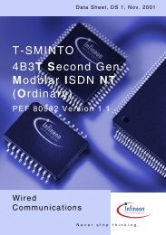
Effective <strong>bit</strong>s: 7.30; THD = −53.35 dB.<br />
Harmonic levels (dB): 2nd = −58.38; 3rd = −60.03; 4th = −57.30; 5th = −69.38; 6th = −67.09.<br />
3.75<br />
5.00 6.25 7.50 8.75 10.00<br />
f (MHz)<br />
Fig.10 Fast Fourier Transform (f clk = 20 MHz; f i = 4.43 MHz).<br />
1995 Mar 09 13
Philips Semiconduc<strong>to</strong>rs<br />
<strong>YUV</strong> 8-<strong>bit</strong> <strong>video</strong> <strong>low</strong>-<strong>power</strong><br />
<strong>analog</strong>-<strong>to</strong>-<strong>digital</strong> <strong>interface</strong><br />
Product specification<br />
TDA8755<br />
APPLICATION INFORMATION<br />
andbook, full pagewidth<br />
AGND<br />
10 nF<br />
n.c.<br />
REG1<br />
1<br />
2<br />
32<br />
31<br />
V CCD<br />
10 nF<br />
D7<br />
DGND<br />
5 V<br />
(3)<br />
AGND<br />
AGND<br />
4.7 µF<br />
220 nF<br />
(1)<br />
INY<br />
REG2<br />
CLPY<br />
3<br />
4<br />
5<br />
30<br />
29<br />
28<br />
D6<br />
D5<br />
D4<br />
5 V<br />
+ 3.35 V<br />
(2)<br />
10 nF<br />
(3)<br />
10 nF<br />
(3)<br />
AGND<br />
AGND<br />
4.7 µF<br />
4.7 µF<br />
(1)<br />
(1)<br />
V CCA<br />
INU<br />
SDN<br />
INV<br />
AGND<br />
CLPU<br />
CLPV<br />
6<br />
7<br />
8<br />
9<br />
10<br />
11<br />
12<br />
TDA8755<br />
27<br />
26<br />
25<br />
24<br />
23<br />
22<br />
21<br />
D3<br />
D2<br />
D1<br />
D0<br />
V CCO<br />
D'3<br />
D'2<br />
DGND<br />
10 nF<br />
5 V<br />
AGND<br />
220 nF<br />
REG3<br />
CE<br />
13<br />
14<br />
20<br />
19<br />
D'1<br />
D'0<br />
CLP<br />
15<br />
18<br />
DGND<br />
HREF<br />
16<br />
17<br />
CLK<br />
MLA735 - 1<br />
The <strong>analog</strong> and <strong>digital</strong> supplies should be separated and decoupled.<br />
(1) Clamp capaci<strong>to</strong>rs must be determined in accordance with the application; recommended values are CLPY = 18 nF, CLPU and CLPV = 33 nF.<br />
(2) It is possible <strong>to</strong> use the reference output voltage pin SDN <strong>to</strong> drive other <strong>analog</strong> circuits under the limits indicated in Chapter “Characteristics”.<br />
(3) Input signal pins have a high bandwidth. It is necessary <strong>to</strong> take special care on PCB layout <strong>to</strong> avoid any interaction from other signals (<strong>digital</strong> clocks<br />
for example).<br />
Fig.11 Application diagram.<br />
1995 Mar 09 14
Philips Semiconduc<strong>to</strong>rs<br />
<strong>YUV</strong> 8-<strong>bit</strong> <strong>video</strong> <strong>low</strong>-<strong>power</strong><br />
<strong>analog</strong>-<strong>to</strong>-<strong>digital</strong> <strong>interface</strong><br />
Product specification<br />
TDA8755<br />
andbook, full pagewidth Y<br />
U<br />
V<br />
TDA8755<br />
12 VDRAM<br />
1 x TMS4C2970<br />
VDRAM<br />
1 x TMS4C2970<br />
12<br />
12<br />
SAA4940<br />
NOISE<br />
REDUCTION<br />
INCLUDING<br />
CROSS-COLOUR<br />
REDUCTION<br />
12<br />
12<br />
SAA7158<br />
VIDEO<br />
ENHANCEMENT,<br />
LFR<br />
PROCESSING<br />
AND DACs<br />
Y<br />
U<br />
V<br />
<strong>to</strong><br />
<strong>video</strong><br />
processor<br />
12<br />
2<br />
2<br />
12/13.5/16/18 MHz control 32/36 MHz<br />
VCO1<br />
VCO2A<br />
MEMORY<br />
H2, V2<br />
VSYNC<br />
CONTROLLER<br />
(32 kHz/100 Hz)<br />
I C<br />
MICROCONTROLLER<br />
2 µC bus<br />
SAA4951<br />
SC1<br />
27 MHz<br />
control 2<br />
data VCO2B<br />
8<br />
PCB83C652<br />
MSA642<br />
<strong>to</strong><br />
deflection<br />
processor<br />
Fig.12 Block diagram of a full-options Improved Picture Quality (IPQ) module.<br />
1995 Mar 09 15
Philips Semiconduc<strong>to</strong>rs<br />
<strong>YUV</strong> 8-<strong>bit</strong> <strong>video</strong> <strong>low</strong>-<strong>power</strong><br />
<strong>analog</strong>-<strong>to</strong>-<strong>digital</strong> <strong>interface</strong><br />
Product specification<br />
TDA8755<br />
andbook, full pagewidth Y<br />
U<br />
TDA8755<br />
12 VDRAM 12<br />
1 x<br />
TMS4C2970<br />
VIDEO<br />
ENHANCEMENT<br />
AND<br />
DACs<br />
Y<br />
U<br />
<strong>to</strong><br />
<strong>video</strong><br />
processor<br />
V<br />
SAA7165<br />
V<br />
2<br />
2<br />
I C bus<br />
12/13.5/16/18 MHz control 32/36 MHz<br />
VCO1<br />
VCO2A<br />
MEMORY<br />
VSYNC<br />
CONTROLLER<br />
H2, V2<br />
(32 kHz/100 Hz)<br />
I C<br />
MICROCONTROLLER<br />
SAA4951<br />
SC1<br />
27 MHz<br />
control 2<br />
data VCO2B<br />
8<br />
MSA643<br />
PCB83C652<br />
<strong>to</strong><br />
deflection<br />
processor<br />
Fig.13 Block diagram of an economic Improved Picture Quality (IPQ) module.<br />
1995 Mar 09 16
Philips Semiconduc<strong>to</strong>rs<br />
<strong>YUV</strong> 8-<strong>bit</strong> <strong>video</strong> <strong>low</strong>-<strong>power</strong><br />
<strong>analog</strong>-<strong>to</strong>-<strong>digital</strong> <strong>interface</strong><br />
Product specification<br />
TDA8755<br />
PACKAGE OUTLINE<br />
SO32: handbook, plastic full pagewidth small outline package; 32 leads; body width 7.5 mm<br />
SOT287-1<br />
D<br />
E<br />
A<br />
X<br />
c<br />
y<br />
H E<br />
v M<br />
A<br />
Z<br />
32 17<br />
pin 1 index<br />
A 2<br />
A 1<br />
L p<br />
Q<br />
(A ) 3<br />
θ<br />
A<br />
1<br />
16<br />
L<br />
e<br />
b p<br />
w M<br />
detail X<br />
0 5 10 mm<br />
scale<br />
DIMENSIONS (inch dimensions are derived from the original mm dimensions)<br />
UNIT<br />
mm<br />
inches<br />
A<br />
max.<br />
2.65<br />
0.10<br />
A 1 A 2 A 3 b p c D (1) E (1) e H E L L p Q v w y Z(1)<br />
0.3<br />
0.1<br />
0.012<br />
0.004<br />
2.45<br />
2.25<br />
0.096<br />
0.086<br />
0.25<br />
0.01<br />
0.49<br />
0.36<br />
0.02<br />
0.01<br />
0.27<br />
0.18<br />
0.011<br />
0.007<br />
20.7<br />
20.3<br />
0.81<br />
0.80<br />
7.6<br />
7.4<br />
0.30<br />
0.29<br />
1.27<br />
0.050<br />
Note<br />
1. Plastic or metal protrusions of 0.15 mm maximum per side are not included.<br />
10.65<br />
10.00<br />
0.42<br />
0.39<br />
1.4<br />
0.055<br />
1.1<br />
0.4<br />
0.043<br />
0.016<br />
1.2<br />
1.0<br />
0.047<br />
0.039<br />
0.25<br />
0.01<br />
0.25 0.1<br />
0.95<br />
0.55 o<br />
8<br />
0.01 0.004<br />
o<br />
0.037 0<br />
0.022<br />
θ<br />
OUTLINE<br />
VERSION<br />
REFERENCES<br />
IEC JEDEC EIAJ<br />
EUROPEAN<br />
PROJECTION<br />
ISSUE DATE<br />
SOT287-1<br />
92-11-17<br />
95-01-25<br />
1995 Mar 09 17
Philips Semiconduc<strong>to</strong>rs<br />
<strong>YUV</strong> 8-<strong>bit</strong> <strong>video</strong> <strong>low</strong>-<strong>power</strong><br />
<strong>analog</strong>-<strong>to</strong>-<strong>digital</strong> <strong>interface</strong><br />
Product specification<br />
TDA8755<br />
SOLDERING<br />
Plastic small outline packages<br />
BY WAVE<br />
During placement and before soldering, the component<br />
must be fixed with a droplet of adhesive. After curing the<br />
adhesive, the component can be soldered. The adhesive<br />
can be applied by screen printing, pin transfer or syringe<br />
dispensing.<br />
Maximum permissible solder temperature is 260 °C, and<br />
maximum duration of package immersion in solder bath is<br />
10 s, if al<strong>low</strong>ed <strong>to</strong> cool <strong>to</strong> less than 150 °C within 6 s.<br />
Typical dwell time is 4 s at 250 °C.<br />
A modified wave soldering technique is recommended<br />
using two solder waves (dual-wave), in which a turbulent<br />
wave with high upward pressure is fol<strong>low</strong>ed by a smooth<br />
laminar wave. Using a mildly-activated flux eliminates the<br />
need for removal of corrosive residues in most<br />
applications.<br />
BY SOLDER PASTE REFLOW<br />
Several techniques exist for ref<strong>low</strong>ing; for example,<br />
thermal conduction by heated belt, infrared, and<br />
vapour-phase ref<strong>low</strong>. Dwell times vary between 50 and<br />
300 s according <strong>to</strong> method. Typical ref<strong>low</strong> temperatures<br />
range from 215 <strong>to</strong> 250 °C.<br />
Preheating is necessary <strong>to</strong> dry the paste and evaporate<br />
the binding agent. Preheating duration: 45 min at 45 °C.<br />
REPAIRING SOLDERED JOINTS (BY HAND-HELD SOLDERING<br />
IRON OR PULSE-HEATED SOLDER TOOL)<br />
Fix the component by first soldering two, diagonally<br />
opposite, end pins. Apply the heating <strong>to</strong>ol <strong>to</strong> the flat part of<br />
the pin only. Contact time must be limited <strong>to</strong> 10 s at up <strong>to</strong><br />
300 °C. When using proper <strong>to</strong>ols, all other pins can be<br />
soldered in one operation within 2 <strong>to</strong> 5 s at between 270<br />
and 320 °C. (Pulse-heated soldering is not recommended<br />
for SO packages.)<br />
For pulse-heated solder <strong>to</strong>ol (resistance) soldering of VSO<br />
packages, solder is applied <strong>to</strong> the substrate by dipping or<br />
by an extra thick tin/lead plating before package<br />
placement.<br />
Ref<strong>low</strong> soldering requires the solder paste (a suspension<br />
of fine solder particles, flux and binding agent) <strong>to</strong> be<br />
applied <strong>to</strong> the substrate by screen printing, stencilling or<br />
pressure-syringe dispensing before device placement.<br />
DEFINITIONS<br />
Data sheet status<br />
Objective specification This data sheet contains target or goal specifications for product development.<br />
Preliminary specification This data sheet contains preliminary data; supplementary data may be published later.<br />
Product specification This data sheet contains final product specifications.<br />
Limiting values<br />
Limiting values given are in accordance with the Absolute Maximum Rating System (IEC 134). Stress above one or<br />
more of the limiting values may cause permanent damage <strong>to</strong> the device. These are stress ratings only and operation<br />
of the device at these or at any other conditions above those given in the Characteristics sections of the specification<br />
is not implied. Exposure <strong>to</strong> limiting values for extended periods may affect device reliability.<br />
Application information<br />
Where application information is given, it is advisory and does not form part of the specification.<br />
LIFE SUPPORT APPLICATIONS<br />
These products are not designed for use in life support appliances, devices, or systems where malfunction of these<br />
products can reasonably be expected <strong>to</strong> result in personal injury. Philips cus<strong>to</strong>mers using or selling these products for<br />
use in such applications do so at their own risk and agree <strong>to</strong> fully indemnify Philips for any damages resulting from such<br />
improper use or sale.<br />
1995 Mar 09 18
Philips Semiconduc<strong>to</strong>rs<br />
<strong>YUV</strong> 8-<strong>bit</strong> <strong>video</strong> <strong>low</strong>-<strong>power</strong><br />
<strong>analog</strong>-<strong>to</strong>-<strong>digital</strong> <strong>interface</strong><br />
Product specification<br />
TDA8755<br />
NOTES<br />
1995 Mar 09 19
Philips Semiconduc<strong>to</strong>rs – a worldwide company<br />
Argentina: IEROD, Av. Juramen<strong>to</strong> 1992 - 14.b, (1428)<br />
BUENOS AIRES, Tel. (541)786 7633, Fax. (541)786 9367<br />
Australia: 34 Waterloo Road, NORTH RYDE, NSW 2113,<br />
Tel. (02)805 4455, Fax. (02)805 4466<br />
Austria: Triester Str. 64, A-1101 WIEN, P.O. Box 213,<br />
Tel. (01)60 101-1236, Fax. (01)60 101-1211<br />
Belgium: Postbus 90050, 5600 PB EINDHOVEN, The Netherlands,<br />
Tel. (31)40 783 749, Fax. (31)40 788 399<br />
Brazil: Rua do Rocio 220 - 5 th floor, Suite 51,<br />
CEP: 04552-903-SÃO PAULO-SP, Brazil.<br />
P.O. Box 7383 (01064-970).<br />
Tel. (011)821-2333, Fax. (011)829-1849<br />
Canada: PHILIPS SEMICONDUCTORS/COMPONENTS:<br />
Tel. (800) 234-7381, Fax. (708) 296-8556<br />
Chile: Av. Santa Maria 0760, SANTIAGO,<br />
Tel. (02)773 816, Fax. (02)777 6730<br />
Colombia: IPRELENSO LTDA, Carrera 21 No. 56-17,<br />
77621 BOGOTA, Tel. (571)249 7624/(571)217 4609,<br />
Fax. (571)217 4549<br />
Denmark: Prags Boulevard 80, PB 1919, DK-2300 COPENHAGEN S,<br />
Tel. (032)88 2636, Fax. (031)57 1949<br />
Finland: Sinikalliontie 3, FIN-02630 ESPOO,<br />
Tel. (9)0-50261, Fax. (9)0-520971<br />
France: 4 Rue du Port-aux-Vins, BP317,<br />
92156 SURESNES Cedex,<br />
Tel. (01)4099 6161, Fax. (01)4099 6427<br />
Germany: P.O. Box 10 63 23, 20043 HAMBURG,<br />
Tel. (040)3296-0, Fax. (040)3296 213.<br />
Greece: No. 15, 25th March Street, GR 17778 TAVROS,<br />
Tel. (01)4894 339/4894 911, Fax. (01)4814 240<br />
Hong Kong: PHILIPS HONG KONG Ltd., 15/F Philips Ind. Bldg.,<br />
24-28 Kung Yip St., KWAI CHUNG, N.T.,<br />
Tel. (852)424 5121, Fax. (852)480 6960/480 6009<br />
India: Philips INDIA Ltd, Shivsagar Estate, A Block ,<br />
Dr. Annie Besant Rd. Worli, Bombay 400 018<br />
Tel. (022)4938 541, Fax. (022)4938 722<br />
Indonesia: Philips House, Jalan H.R. Rasuna Said Kav. 3-4,<br />
P.O. Box 4252, JAKARTA 12950,<br />
Tel. (021)5201 122, Fax. (021)5205 189<br />
Ireland: Newstead, Clonskeagh, DUBLIN 14,<br />
Tel. (01)640 000, Fax. (01)640 200<br />
Italy: PHILIPS SEMICONDUCTORS S.r.l.,<br />
Piazza IV Novembre 3, 20124 MILANO,<br />
Tel. (0039)2 6752 2531, Fax. (0039)2 6752 2557<br />
Japan: Philips Bldg 13-37, Kohnan 2 -chome, Mina<strong>to</strong>-ku, TOKYO 108,<br />
Tel. (03)3740 5028, Fax. (03)3740 0580<br />
Korea: (Republic of) Philips House, 260-199 Itaewon-dong,<br />
Yongsan-ku, SEOUL, Tel. (02)794-5011, Fax. (02)798-8022<br />
Malaysia: No. 76 Jalan Universiti, 46200 PETALING JAYA,<br />
SELANGOR, Tel. (03)750 5214, Fax. (03)757 4880<br />
Mexico: 5900 Gateway East, Suite 200, EL PASO, TX 79905,<br />
Tel. 9-5(800)234-7381, Fax. (708)296-8556<br />
Netherlands: Postbus 90050, 5600 PB EINDHOVEN, Bldg. VB<br />
Tel. (040)783749, Fax. (040)788399<br />
New Zealand: 2 Wagener Place, C.P.O. Box 1041, AUCKLAND,<br />
Tel. (09)849-4160, Fax. (09)849-7811<br />
Norway: Box 1, Manglerud 0612, OSLO,<br />
Tel. (022)74 8000, Fax. (022)74 8341<br />
Pakistan: Philips Electrical Industries of Pakistan Ltd.,<br />
Exchange Bldg. ST-2/A, Block 9, KDA Scheme 5, Clif<strong>to</strong>n,<br />
KARACHI 75600, Tel. (021)587 4641-49,<br />
Fax. (021)577035/5874546.<br />
Philippines: PHILIPS SEMICONDUCTORS PHILIPPINES Inc,<br />
106 Valero St. Salcedo Village, P.O. Box 2108 MCC, MAKATI,<br />
Metro MANILA, Tel. (02)810 0161, Fax. (02)817 3474<br />
Portugal: PHILIPS PORTUGUESA, S.A.,<br />
Rua dr. António Loureiro Borges 5, Arquiparque - Miraflores,<br />
Apartado 300, 2795 LINDA-A-VELHA,<br />
Tel. (01)4163160/4163333, Fax. (01)4163174/4163366.<br />
Singapore: Lorong 1, Toa Payoh, SINGAPORE 1231,<br />
Tel. (65)350 2000, Fax. (65)251 6500<br />
South Africa: S.A. PHILIPS Pty Ltd.,<br />
195-215 Main Road Martindale, 2092 JOHANNESBURG,<br />
P.O. Box 7430 Johannesburg 2000,<br />
Tel. (011)470-5911, Fax. (011)470-5494.<br />
Spain: Balmes 22, 08007 BARCELONA,<br />
Tel. (03)301 6312, Fax. (03)301 42 43<br />
Sweden: Kottbygatan 7, Akalla. S-164 85 STOCKHOLM,<br />
Tel. (0)8-632 2000, Fax. (0)8-632 2745<br />
Switzerland: Allmendstrasse 140, CH-8027 ZÜRICH,<br />
Tel. (01)488 2211, Fax. (01)481 77 30<br />
Taiwan: PHILIPS TAIWAN Ltd., 23-30F, 66, Chung Hsiao West<br />
Road, Sec. 1. Taipeh, Taiwan ROC, P.O. Box 22978,<br />
TAIPEI 100, Tel. (02)388 7666, Fax. (02)382 4382.<br />
Thailand: PHILIPS ELECTRONICS (THAILAND) Ltd.,<br />
209/2 Sanpavuth-Bangna Road Prakanong,<br />
Bangkok 10260, THAILAND,<br />
Tel. (662)398-0141, Fax. (662)398-3319.<br />
Turkey: Talatpasa Cad. No. 5, 80640 GÜLTEPE/ISTANBUL,<br />
Tel. (0 212)279 2770, Fax. (0212)282 6707<br />
United Kingdom: Philips Semiconduc<strong>to</strong>rs LTD.,<br />
276 Bath Road, Hayes, MIDDLESEX UB3 5BX,<br />
Tel. (0181)730-5000, Fax. (0181)754-8421<br />
United States: 811 East Arques Avenue, SUNNYVALE,<br />
CA 94088-3409, Tel. (800)234-7381, Fax. (708)296-8556<br />
Uruguay: Coronel Mora 433, MONTEVIDEO,<br />
Tel. (02)70-4044, Fax. (02)92 0601<br />
Internet: http://www.semiconduc<strong>to</strong>rs.philips.com/ps/<br />
For all other countries apply <strong>to</strong>: Philips Semiconduc<strong>to</strong>rs,<br />
International Marketing and Sales, Building BE-p,<br />
P.O. Box 218, 5600 MD, EINDHOVEN, The Netherlands,<br />
Telex 35000 phtcnl, Fax. +31-40-724825<br />
SCD38 © Philips Electronics N.V. 1995<br />
All rights are reserved. Reproduction in whole or in part is prohi<strong>bit</strong>ed without the<br />
prior written consent of the copyright owner.<br />
The information presented in this document does not form part of any quotation<br />
or contract, is believed <strong>to</strong> be accurate and reliable and may be changed without<br />
notice. No liability will be accepted by the publisher for any consequence of its<br />
use. Publication thereof does not convey nor imply any license under patent- or<br />
other industrial or intellectual property rights.<br />
Printed in The Netherlands<br />
533061/30/03/pp20 Date of release: 1995 Mar 09<br />
Document order number: 9397 750 00027<br />
Philips Semiconduc<strong>to</strong>rs