PROFET® BTS 728 L2 Smart High-Side Power Switch Two ...
PROFET® BTS 728 L2 Smart High-Side Power Switch Two ...
PROFET® BTS 728 L2 Smart High-Side Power Switch Two ...

You also want an ePaper? Increase the reach of your titles
YUMPU automatically turns print PDFs into web optimized ePapers that Google loves.
<strong>PROFET®</strong> <strong>BTS</strong> <strong>728</strong> <strong>L2</strong><br />
<strong>Smart</strong> <strong>High</strong>-<strong>Side</strong> <strong>Power</strong> <strong>Switch</strong><br />
<strong>Two</strong> Channels: 2 x 60mΩ<br />
Status Feedback<br />
Product Summary<br />
Package<br />
Operating Voltage V bb(on) 4.75...41V<br />
Active channels one two parallel<br />
On-state Resistance R ON 60mΩ 30mΩ<br />
Nominal load current I L(NOM) 4.0A 6.0A<br />
Current limitation I L(SCr) 17A 17A<br />
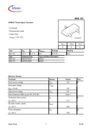
P-DSO-20-9<br />
General Description<br />
• N channel vertical power MOSFET with charge pump, ground referenced CMOS compatible input and<br />
diagnostic feedback, monolithically integrated in <strong>Smart</strong> SIPMOS ® technology.<br />
• Fully protected by embedded protection functions<br />
Applications<br />
• µC compatible high-side power switch with diagnostic feedback for 5V, 12V and 24V grounded loads<br />
• All types of resistive, inductive and capacitve loads<br />
• Most suitable for loads with high inrush currents, so as lamps<br />
• Replaces electromechanical relays, fuses and discrete circuits<br />
Basic Functions<br />
• Very low standby current<br />
• CMOS compatible input<br />
• Improved electromagnetic compatibility (EMC)<br />
• Fast demagnetization of inductive loads<br />
• Stable behaviour at undervoltage<br />
• Wide operating voltage range<br />
• Logic ground independent from load ground<br />
Protection Functions<br />
• Short circuit protection<br />
• Overload protection<br />
• Current limitation<br />
• Thermal shutdown<br />
• Overvoltage protection (including load dump) with external<br />
resistor<br />
• Reverse battery protection with external resistor<br />
• Loss of ground and loss of V bb protection<br />
• Electrostatic discharge protection (ESD)<br />
Diagnostic Function<br />
• Diagnostic feedback with open drain output<br />
• Open load detection in ON-state<br />
• Feedback of thermal shutdown in ON-state<br />
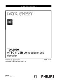
Block Diagram<br />
IN1<br />
ST1<br />
IN2<br />
ST2<br />
Vbb<br />
Logic<br />
Channel<br />
1<br />
Logic<br />
Channel<br />
2<br />
PROFET<br />
GND<br />
OUT 1<br />
Load 1<br />
OUT 2<br />
Load 2<br />
Semiconductor Group Page 1 of 14 1999-Mar-23
<strong>BTS</strong> <strong>728</strong> <strong>L2</strong><br />
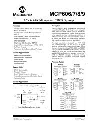
Functional diagram<br />
overvoltage<br />
protection<br />
internal<br />
voltage supply<br />
logic<br />
gate<br />
control<br />
+<br />
charge<br />
pump<br />
current limit<br />
clamp for<br />
inductive load<br />
VBB<br />
OUT1<br />
IN1<br />
ST1<br />
ESD<br />
temperature<br />
sensor<br />
Open load<br />
detection<br />
LOAD<br />
GND1<br />
Channel 1<br />
IN2<br />
ST2<br />
GND2<br />
Control and protection circuit<br />
of<br />
channel 2<br />
OUT2<br />
PROFET<br />
Pin Definitions and Functions<br />
Pin Symbol Function<br />
1,10,<br />
11,12,<br />
15,16,<br />
19,20<br />
V bb Positive power supply voltage. Design the<br />
wiring for the simultaneous max. short circuit<br />
currents from channel 1 to 2 and also for low<br />
thermal resistance<br />
3 IN1 Input 1,2, activates channel 1,2 in case of<br />
7 IN2 logic high signal<br />
17,18 OUT1 Output 1,2, protected high-side power output<br />
13,14 OUT2 of channel 1,2. Design the wiring for the max.<br />
short circuit current<br />
4 ST1 Diagnostic feedback 1,2 of channel 1,2,<br />
8 ST2 open drain, low on failure<br />
2 GND1 Ground 1 of chip 1 (channel 1)<br />
6 GND2 Ground 2 of chip 2 (channel 2)<br />
5,9 N.C. Not Connected<br />
Pin configuration<br />
(top view)<br />
V bb 1 • 20 V bb<br />
GND1 2 19 V bb<br />
IN1 3 18 OUT1<br />
ST1 4 17 OUT1<br />
N.C. 5 16 V bb<br />
GND2 6 15 V bb<br />
IN2 7 14 OUT2<br />
ST2 8 13 OUT2<br />
N.C. 9 12 V bb<br />
V bb 10 11 V bb<br />
Semiconductor Group Page 2 1999-Mar-23
<strong>BTS</strong> <strong>728</strong> <strong>L2</strong><br />
Maximum Ratings at T j = 25°C unless otherwise specified<br />
Parameter Symbol Values Unit<br />
Supply voltage (overvoltage protection see page 4) V bb 43 V<br />
Supply voltage for full short circuit protection<br />
V bb 24 V<br />
T j,start = -40 ...+150°C<br />
Load current (Short-circuit current, see page 5) I L self-limited A<br />
Load dump protection 1) V LoadDump = V A + V s , V A = 13.5 V V Load dump 3) 60 V<br />
R<br />
2) I = 2 Ω, t d = 200 ms; IN = low or high,<br />
each channel loaded with R L = 8.0 Ω,<br />
Operating temperature range<br />
T j<br />
-40 ...+150 °C<br />
Storage temperature range<br />
T stg -55 ...+150<br />
<strong>Power</strong> dissipation (DC) 4)<br />
T a = 25°C: P tot 3.7 W<br />
(all channels active)<br />
T a = 85°C:<br />
1.9<br />
Maximal switchable inductance, single pulse<br />
V bb = 12V, T j,start = 150°C 4) ,<br />
I L = 4.0 A, E AS = 220 mJ, 0 Ω<br />
one channel: Z L<br />
19.9 mH<br />
I L = 6.0 A, E AS = 540 mJ, 0 Ω two parallel channels:<br />
22.3<br />
see diagrams on page 9<br />
Electrostatic discharge capability (ESD) IN: V ESD 1.0 kV<br />
(Human Body Model)<br />
ST:<br />
4.0<br />
out to all other pins shorted:<br />
8.0<br />
acc. MIL-STD883D, method 3015.7 and ESD assn. std. S5.1-1993<br />
R=1.5kΩ; C=100pF<br />
Input voltage (DC) V IN -10 ... +16 V<br />
Current through input pin (DC)<br />
Current through status pin (DC)<br />
I IN<br />
I ST<br />
±2.0<br />
±5.0<br />
mA<br />
see internal circuit diagram page 8<br />
Thermal Characteristics<br />
Parameter and Conditions Symbol Values Unit<br />
min typ Max<br />
Thermal resistance<br />
junction - soldering point 4),5) each channel: R thjs -- -- 13.5 K/W<br />
junction - ambient 4)<br />
one channel active:<br />
all channels active:<br />
R thja --<br />
--<br />
41<br />
34<br />
--<br />
--<br />
1) Supply voltages higher than V bb(AZ) require an external current limit for the GND and status pins (a 150Ω<br />
resistor for the GND connection is recommended.<br />
2) R I = internal resistance of the load dump test pulse generator<br />
3) V Load dump is setup without the DUT connected to the generator per ISO 7637-1 and DIN 40839<br />
4) Device on 50mm*50mm*1.5mm epoxy PCB FR4 with 6cm 2 (one layer, 70µm thick) copper area for V bb<br />
connection. PCB is vertical without blown air. See page 14<br />
5) Soldering point: upper side of solder edge of device pin 15. See page 14<br />
Semiconductor Group Page 3 1999-Mar-23
<strong>BTS</strong> <strong>728</strong> <strong>L2</strong><br />
Electrical Characteristics<br />
Parameter and Conditions, each of the two channels Symbol Values Unit<br />
at Tj = -40...+150°C, V bb = 12 V unless otherwise specified min typ Max<br />
Load <strong>Switch</strong>ing Capabilities and Characteristics<br />
On-state resistance (V bb to OUT); IL = 2 A, V bb<br />
≥ 7V<br />
each channel, T j = 25°C:<br />
T j = 150°C:<br />
R ON -- 50<br />
100<br />
60<br />
120<br />
mΩ<br />
two parallel channels, T j = 25°C:<br />
see diagram, page 10<br />
Nominal load current one channel active:<br />
two parallel channels active:<br />
Device on PCB 6) , Ta = 85°C, Tj ≤ 150°C<br />
Output current while GND disconnected or pulled up;<br />
Vbb = 30 V, VIN = 0,<br />
see diagram page 8; (not tested specified by design)<br />
Turn-on time 7) IN to 90% V OUT :<br />
Turn-off time IN to 10% V OUT :<br />
R L = 12 Ω<br />
Slew rate on 7)<br />
10 to 30% V OUT , R L = 12 Ω:<br />
Slew rate off 7)<br />
70 to 40% V OUT , R L = 12 Ω:<br />
I L(NOM) 3.6<br />
5.5<br />
25<br />
4.0<br />
6.0<br />
30<br />
-- A<br />
I L(GNDhigh) -- -- 2 mA<br />
t on<br />
30<br />
t off 30<br />
100<br />
100<br />
200<br />
200<br />
µs<br />
dV/dt on 0.1 -- 1 V/µs<br />
-dV/dt off 0.1 -- 1 V/µs<br />
Operating Parameters<br />
Operating voltage<br />
Tj=-40<br />
T j<br />
=25...150°C:<br />
T j =-40°C:<br />
T j =25...150°C:<br />
T j =-40°C...25°C:<br />
T j =150°C:<br />
Overvoltage protection 8)<br />
I bb = 40 mA<br />
Standby current 9)<br />
V IN = 0; see diagram page 10<br />
Leakage output current (included in I bb(off) )<br />
VIN = 0<br />
Operating current 10) , V IN = 5V,<br />
I GND = I GND1 + I GND2 ,<br />
one channel on:<br />
two channels on:<br />
V bb(on) 4.75 --<br />
--<br />
V bb(AZ) 41<br />
43<br />
I bb(off) --<br />
--<br />
--<br />
47<br />
10<br />
--<br />
41<br />
43<br />
--<br />
52<br />
18<br />
50<br />
V<br />
V<br />
µA<br />
I L(off) -- 1 10 µA<br />
I GND -- 0.8<br />
-- 1.6<br />
1.5<br />
3.0<br />
mA<br />
6) Device on 50mm*50mm*1.5mm epoxy PCB FR4 with 6cm 2 (one layer, 70µm thick) copper area for V bb<br />
connection. PCB is vertical without blown air. See page 14<br />
7) See timing diagram on page 11.<br />
8) Supply voltages higher than V bb(AZ) require an external current limit for the GND and status pins (a 150Ω<br />
resistor for the GND connection is recommended). See also VON(CL) in table of protection functions and<br />
circuit diagram on page 8.<br />
9) Measured with load; for the whole device; all channels off<br />
10) Add IST , if I ST > 0<br />
Semiconductor Group Page 4 1999-Mar-23
<strong>BTS</strong> <strong>728</strong> <strong>L2</strong><br />
Parameter and Conditions, each of the two channels Symbol Values Unit<br />
at Tj = -40...+150°C, V bb = 12 V unless otherwise specified min typ Max<br />
Protection Functions<br />
Current limit, (see timing diagrams, page 12)<br />
Tj =-40°C:<br />
Tj =25°C:<br />
Tj =+150°C:<br />
Repetitive short circuit current limit,<br />
T j = T jt<br />
each channel<br />
two parallel channels<br />
(see timing diagrams, page 12)<br />
Initial short circuit shutdown time<br />
T j,start =25°C:<br />
(see timing diagrams on page 12)<br />
Output clamp (inductive load switch off) 11)<br />
at VON(CL) = Vbb - VOUT, IL= 40 mA Tj =-40°C:<br />
Tj =25°C...150°C:<br />
I L(lim) 21<br />
17<br />
12<br />
I L(SCr) --<br />
--<br />
28<br />
22<br />
16<br />
17<br />
17<br />
36<br />
31<br />
24<br />
--<br />
--<br />
t off(SC) -- 2.4 -- ms<br />
V ON(CL) 41<br />
43<br />
Thermal overload trip temperature T jt 150 -- -- °C<br />
Thermal hysteresis ∆T jt -- 10 -- K<br />
Reverse Battery<br />
Reverse battery voltage 12) -V bb -- -- 32 V<br />
Drain-source diode voltage (Vout > Vbb)<br />
-V ON -- 600 -- mV<br />
IL = - 4.0 A, Tj = +150°C<br />
--<br />
47<br />
--<br />
52<br />
A<br />
A<br />
V<br />
11) If channels are connected in parallel, output clamp is usually accomplished by the channel with the lowest<br />
V ON(CL)<br />
12) Requires a 150 Ω resistor in GND connection. The reverse load current through the intrinsic drain-source<br />
diode has to be limited by the connected load. <strong>Power</strong> dissipation is higher compared to normal operating<br />
conditions due to the voltage drop across the drain-source diode. The temperature protection is not active<br />
during reverse current operation! Input and Status currents have to be limited (see max. ratings page 3 and<br />
circuit page 8).<br />
Semiconductor Group Page 5 1999-Mar-23
<strong>BTS</strong> <strong>728</strong> <strong>L2</strong><br />
Parameter and Conditions, each of the two channels Symbol Values Unit<br />
at Tj = -40...+150°C, V bb = 12 V unless otherwise specified min typ Max<br />
Diagnostic Characteristics<br />
Open load detection current, (on-condition)<br />
each channel I L (OL)1 10 -- 500 mA<br />
Input and Status Feedback 13)<br />
Input resistance<br />
R I 2.5 3.5 6 kΩ<br />
(see circuit page 8)<br />
Input turn-on threshold voltage V IN(T+) 1.7 -- 3.2 V<br />
Input turn-off threshold voltage V IN(T-) 1.5 -- -- V<br />
Input threshold hysteresis ∆ V IN(T) -- 0.5 -- V<br />
Off state input current V IN = 0.4 V: I IN(off) 1 -- 50 µA<br />
On state input current V IN = 5 V: I IN(on) 20 50 90 µA<br />
Delay time for status with open load after switch t d(ST OL4) 100 520 900 µs<br />
off; (see diagram on page 13)<br />
Status output (open drain)<br />
Zener limit voltage<br />
I ST = +1.6 mA: V ST(high)<br />
6.1 -- V<br />
ST low voltage<br />
I ST = +1.6 mA: V ST(low) -- -- 0.4<br />
13) If ground resistors R GND are used, add the voltage drop across these resistors.<br />
Semiconductor Group Page 6 1999-Mar-23
<strong>BTS</strong> <strong>728</strong> <strong>L2</strong><br />
Truth Table<br />
Channel 1 Input 1 Output 1 Status 1<br />
Channel 2 Input 2 Output 2 Status 2<br />
Normal<br />
operation<br />
Open load<br />
Overtemperature<br />
level level <strong>BTS</strong> <strong>728</strong><strong>L2</strong><br />
L<br />
H<br />
L<br />
H<br />
L<br />
H<br />
L<br />
H<br />
Z<br />
H<br />
L<br />
L<br />
H<br />
H<br />
H<br />
L<br />
H<br />
L<br />
L = "Low" Level X = don’t care Z = high impedance, potential depends on external circuit<br />
H = "<strong>High</strong>" Level Status signal valid after the time delay shown in the timing diagrams<br />
Parallel switching of channel 1 and 2 is easily possible by connecting the inputs and outputs in parallel. The<br />
status outputs ST1 and ST2 have to be configured as a ’Wired OR’ function with a single pull-up resistor.<br />
Terms<br />
I bb<br />
I ST1<br />
R GND1<br />
Chip 1<br />
V IN1<br />
I IN1<br />
V ST1<br />
3<br />
4<br />
IN1<br />
ST1<br />
Leadframe<br />
V bb<br />
PROFET<br />
GND1<br />
2<br />
I GND1<br />
OUT1<br />
17,18<br />
V ON1<br />
Leadframe<br />
I IN2<br />
V bb<br />
IN2<br />
7<br />
I <strong>L2</strong> V ON2<br />
PROFET OUT2<br />
I ST2 13,14<br />
Chip 2<br />
ST2<br />
8<br />
V V ST2<br />
GND2<br />
IN2<br />
6<br />
I GND2<br />
V OUT2<br />
R GND2<br />
V bb<br />
I L1<br />
V OUT1<br />
Leadframe (V bb ) is connected to pin 1,10,11,12,15,16,19,20<br />
External R GND optional; two resistors R GND1 , R GND2 = 150 Ω or a single resistor R GND = 75 Ω for reverse<br />
battery protection up to the max. operating voltage.<br />
Semiconductor Group Page 7 1999-Mar-23
Input circuit (ESD protection), IN1 or IN2<br />
IN<br />
R<br />
I<br />
ESD-ZD I<br />
GND<br />
The use of ESD zener diodes as voltage clamp at DC<br />
conditions is not recommended.<br />
Status output, ST1 or ST2<br />
R ST(ON)<br />
GND<br />
I<br />
I<br />
ESD-<br />
ZD<br />
ST<br />
+5V<br />
ESD-Zener diode: 6.1 V typ., max 5.0 mA; R ST(ON) < 375 Ω<br />
at 1.6 mA. The use of ESD zener diodes as voltage clamp at<br />
DC conditions is not recommended.<br />
<strong>BTS</strong> <strong>728</strong> <strong>L2</strong><br />
Overvolt. and reverse batt. protection<br />
+ 5V<br />
R<br />
ST<br />
R<br />
ST<br />
IN<br />
ST<br />
R<br />
I<br />
V Z1<br />
Logic<br />
R<br />
GND<br />
Signal GND<br />
V Z2<br />
GND<br />
OUT<br />
PROFET<br />
+ V bb<br />
R<br />
Load<br />
Load GND<br />
V Z1 = 6.1 V typ., V Z2 = 47 V typ., R GND = 150 Ω,<br />
R ST = 15 kΩ, R I = 3.5 kΩ typ.<br />
In case of reverse battery the load current has to be<br />
limited by the load. Temperature protection is not active<br />
Open-load detection OUT1 or OUT2<br />
ON-state diagnostic<br />
Open load, if V ON < R ON·I L(OL) ; IN high<br />
+ V bb<br />
Inductive and overvoltage output clamp,<br />
OUT1 or OUT2<br />
+V bb<br />
OUT<br />
Logic<br />
unit<br />
ON<br />
Open load<br />
detection<br />
V ON<br />
OUT<br />
V Z<br />
V ON<br />
GND disconnect<br />
<strong>Power</strong> GND<br />
IN<br />
V<br />
bb<br />
VON clamped to VON(CL) = 47 V typ.<br />
PROFET<br />
OUT<br />
ST<br />
GND<br />
V bb<br />
V IN<br />
V ST V GND<br />
Any kind of load. In case of IN = high is VOUT ≈ VIN - VIN(T+).<br />
Due to VGND > 0, no VST = low signal available.<br />
Semiconductor Group Page 8 1999-Mar-23
GND disconnect with GND pull up<br />
V<br />
IN bb<br />
Inductive load switch-off energy<br />
dissipation<br />
E bb<br />
<strong>BTS</strong> <strong>728</strong> <strong>L2</strong><br />
E AS<br />
V bb<br />
V IN<br />
V ST<br />
ST<br />
PROFET OUT<br />
GND<br />
V GND<br />
=<br />
IN<br />
ST<br />
V<br />
bb<br />
PROFET<br />
GND<br />
OUT<br />
L<br />
Z L{<br />
E Load<br />
E<br />
L<br />
Any kind of load. If VGND > VIN - VIN(T+) device stays off<br />
Due to VGND > 0, no VST = low signal available.<br />
Vbb disconnect with energized inductive<br />
load<br />
Energy stored in load inductance:<br />
E L = 1 /2·L·I 2 L<br />
While demagnetizing load inductance, the energy<br />
dissipated in PROFET is<br />
R L<br />
E R<br />
high<br />
IN<br />
ST<br />
V<br />
bb<br />
PROFET<br />
GND<br />
OUT<br />
E AS = E bb + E L - E R = ∫ VON(CL)·i L (t) dt,<br />
with an approximate solution for R L > 0 Ω:<br />
E AS = IL· L<br />
IL·RL<br />
(V<br />
2·R bb + |V OUT(CL) |) ln (1+<br />
L |V OUT(CL) | )<br />
V bb<br />
For inductive load currents up to the limits defined by Z L<br />
(max. ratings and diagram on page 9) each switch is<br />
protected against loss of V bb .<br />
Consider at your PCB layout that in the case of Vbb disconnection<br />
with energized inductive load all the load current<br />
flows through the GND connection.<br />
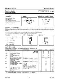
Maximum allowable load inductance for<br />
a single switch off (one channel) 4)<br />
L = f (I L ); T j,start = 150°C, V bb = 12 V, R L = 0 Ω<br />
Z L [mH]<br />
1000<br />
100<br />
10<br />
1<br />
2 3 4 5 6 7 8 9 10 11 12<br />
I L [A]<br />
Semiconductor Group Page 9 1999-Mar-23
<strong>BTS</strong> <strong>728</strong> <strong>L2</strong><br />
Typ. on-state resistance<br />
R ON = f (V bb ,T j ); I L = 2 A, IN = high<br />
R ON [mOhm]<br />
125<br />
100<br />
Tj = 150°C<br />
75<br />
50<br />
25°C<br />
-40°C<br />
25<br />
0<br />
3 5 7 9 30 40<br />
V bb [V]<br />
Typ. standby current<br />
I bb(off) = f (T j ); V bb = 9...34 V, IN1,2 = low<br />
I bb(off) [µA]<br />
45<br />
40<br />
35<br />
30<br />
25<br />
20<br />
15<br />
10<br />
5<br />
0<br />
-50 0 50 100 150 200<br />
T j [°C]<br />
Semiconductor Group Page 10 1999-Mar-23
<strong>BTS</strong> <strong>728</strong> <strong>L2</strong><br />
Timing diagrams<br />
Both channels are symmetric and consequently the diagrams are valid for channel 1 and<br />
channel 2<br />
Figure 1a: V bb turn on:<br />
IN1<br />
Figure 2b: <strong>Switch</strong>ing a lamp:<br />
IN2<br />
IN<br />
V<br />
bb<br />
V<br />
OUT1<br />
V OUT2<br />
ST<br />
V<br />
OUT<br />
ST1 open drain<br />
I<br />
L<br />
ST2 open drain<br />
t<br />
t<br />
Figure 2a: <strong>Switch</strong>ing a resistive load,<br />
turn-on/off time and slew rate definition:<br />
IN<br />
The initial peak current should be limited by the lamp and not by the<br />
current limit of the device.<br />
Figure 2c: <strong>Switch</strong>ing an inductive load<br />
IN<br />
V OUT<br />
90%<br />
t on<br />
dV/dtoff<br />
ST<br />
10%<br />
dV/dton<br />
t<br />
off<br />
V<br />
OUT<br />
I L<br />
I<br />
L<br />
t<br />
I L(OL)<br />
t<br />
*) if the time constant of load is too large, open-load-status may<br />
occur<br />
Semiconductor Group Page 11 1999-Mar-23
<strong>BTS</strong> <strong>728</strong> <strong>L2</strong><br />
Figure 3a: Turn on into short circuit:<br />
shut down by overtemperature, restart by cooling<br />
Figure 4a: Overtemperature:<br />
Reset if T j
<strong>BTS</strong> <strong>728</strong> <strong>L2</strong><br />
Figure 5b: Open load: turn on/off to open load<br />
IN<br />
ST<br />
t d(STOL4)<br />
I<br />
L<br />
t<br />
Semiconductor Group Page 13 1999-Mar-23
<strong>BTS</strong> <strong>728</strong> <strong>L2</strong><br />
Package and Ordering Code<br />
Standard: P-DSO-20-9<br />
Sales Code<br />
Ordering Code<br />
All dimensions in millimetres<br />
<strong>BTS</strong> <strong>728</strong> <strong>L2</strong><br />
Q67060-S7014-A2<br />
Definition of soldering point with temperature T s :<br />
upper side of solder edge of device pin 15.<br />
Published by Siemens AG, Bereich Bauelemente, Vertrieb,<br />
Produkt-Information, Balanstraße 73, D-81541 München<br />
© Siemens AG 1999. All Rights Reserved<br />
As far as patents or other rights of third parties are concerned,<br />
liability is only assumed for components per se, not for applications,<br />
processes and circuits implemented within components or assemblies.<br />
The information describes a type of component and shall not<br />
be considered as warranted characteristics. The characteristics for<br />
which SIEMENS grants a warranty will only be specified in the<br />
purchase contract. Terms of delivery and rights to change design<br />
reserved. For questions on technology, delivery and prices please<br />
contact the Offices of Semiconductor Group in Germany or the<br />
Siemens Companies and Representatives woldwide (see address<br />
list). Due to technical requirements components may contain dangerous<br />
substances. For information on the type in question please<br />
contact your nearest Siemens Office, Semiconductor Group.<br />
Siemens AG is an approved CECC manufacturer.<br />
Packing: Please use the recycling operators known to you. We can<br />
also help you - get in touch with your nearest sales office. By<br />
agreement we will take packing material back, if it is sorted. You<br />
must bear the costs of transport. For packing material that is returned<br />
to us unsorted or which we are not obliged to accept we shall<br />
have to invoice you for any costs incurred.<br />
Components used in life-support devices or systems must be<br />
expressly authorised for such purpose! Critical components 14) of<br />
the Semiconductor Group of Siemens AG, may only be used in life<br />
supporting devices or systems 15) with the express written approval<br />
of the Semiconductor Group of Siemens AG.<br />
Pin 15<br />
Printed circuit board (FR4, 1.5mm thick, one layer<br />
70µm, 6cm 2 active heatsink area) as a reference for<br />
max. power dissipation P tot , nominal load current<br />
I L(NOM) and thermal resistance R thja<br />
14) A critical component is a component used in a life-support<br />
device or system whose failure can reasonably be expected to<br />
cause the failure of that life-support device or system, or to<br />
affect its safety or effectiveness of that device or system.<br />
15) Life support devices or systems are intended (a) to be<br />
implanted in the human body or (b) support and/or maintain<br />
and sustain and/or protect human life. If they fail, it is<br />
reasonably to assume that the health of the user or other<br />
persons may be endangered.<br />
Semiconductor Group Page 14 1999-Mar-23