PEF 80902 - DigiKey
PEF 80902 - DigiKey
PEF 80902 - DigiKey

You also want an ePaper? Increase the reach of your titles
YUMPU automatically turns print PDFs into web optimized ePapers that Google loves.
Data Sheet, DS 1, Nov. 2001<br />
T-SMINTO<br />
4B3T Second Gen.<br />
Modular ISDN NT<br />
(Ordinary)<br />
<strong>PEF</strong> <strong>80902</strong> Version 1.1<br />
Wired<br />
Communications<br />
Never stop thinking.
Edition 2001-11-12<br />
Published by Infineon Technologies AG,<br />
St.-Martin-Strasse 53,<br />
D-81541 München, Germany<br />
© Infineon Technologies AG 2001.<br />
All Rights Reserved.<br />
Attention please!<br />
The information herein is given to describe certain components and shall not be considered as warranted<br />
characteristics.<br />
Terms of delivery and rights to technical change reserved.<br />
We hereby disclaim any and all warranties, including but not limited to warranties of non-infringement, regarding<br />
circuits, descriptions and charts stated herein.<br />
Infineon Technologies is an approved CECC manufacturer.<br />
Information<br />
For further information on technology, delivery terms and conditions and prices please contact your nearest<br />
Infineon Technologies Office in Germany or our Infineon Technologies Representatives worldwide (see address<br />
list).<br />
Warnings<br />
Due to technical requirements components may contain dangerous substances. For information on the types in<br />
question please contact your nearest Infineon Technologies Office.<br />
Infineon Technologies Components may only be used in life-support devices or systems with the express written<br />
approval of Infineon Technologies, if a failure of such components can reasonably be expected to cause the failure<br />
of that life-support device or system, or to affect the safety or effectiveness of that device or system. Life support<br />
devices or systems are intended to be implanted in the human body, or to support and/or maintain and sustain<br />
and/or protect human life. If they fail, it is reasonable to assume that the health of the user or other persons may<br />
be endangered.
Data Sheet, DS 1, Nov. 2001<br />
T-SMINTO<br />
4B3T Second Gen.<br />
Modular ISDN NT<br />
(Ordinary)<br />
<strong>PEF</strong> <strong>80902</strong> Version 1.1<br />
Wired<br />
Communications<br />
Never stop thinking.
<strong>PEF</strong> <strong>80902</strong><br />
Revision History: 2001-11-12 DS 1<br />
Previous Version: Preliminary Data Sheet 06.01<br />
Page<br />
Subjects (major changes since last revision)<br />
Table 10 Additional C/I-command LTD<br />
Figure 12<br />
Chapter 2.3.7.4<br />
Chapter 4.2 Input Leakage Current AIN, BIN: max. 30µA<br />
Chapter 4.4 Reduced power consumption<br />
For questions on technology, delivery and prices please contact the Infineon<br />
Technologies Offices in Germany or the Infineon Technologies Companies and<br />
Representatives worldwide: see our webpage at http://www.infineon.com
<strong>PEF</strong> <strong>80902</strong><br />
Table of Contents<br />
Page<br />
1 Overview . . . . . . . . . . . . . . . . . . . . . . . . . . . . . . . . . . . . . . . . . . . . . . . . . . . 1<br />
1.1 References . . . . . . . . . . . . . . . . . . . . . . . . . . . . . . . . . . . . . . . . . . . . . . . . . 2<br />
1.2 Features . . . . . . . . . . . . . . . . . . . . . . . . . . . . . . . . . . . . . . . . . . . . . . . . . . . . 3<br />
1.3 Not Supported are ... . . . . . . . . . . . . . . . . . . . . . . . . . . . . . . . . . . . . . . . . . . 4<br />
1.4 Pin Configuration . . . . . . . . . . . . . . . . . . . . . . . . . . . . . . . . . . . . . . . . . . . . . 5<br />
1.5 Block Diagram . . . . . . . . . . . . . . . . . . . . . . . . . . . . . . . . . . . . . . . . . . . . . . . 6<br />
1.6 Pin Definitions and Functions . . . . . . . . . . . . . . . . . . . . . . . . . . . . . . . . . . . 7<br />
1.6.1 Specific Pins and Test Modes . . . . . . . . . . . . . . . . . . . . . . . . . . . . . . . . . 9<br />
1.7 System Integration . . . . . . . . . . . . . . . . . . . . . . . . . . . . . . . . . . . . . . . . . . . 11<br />
2 Functional Description . . . . . . . . . . . . . . . . . . . . . . . . . . . . . . . . . . . . . . 13<br />
2.1 Reset Generation . . . . . . . . . . . . . . . . . . . . . . . . . . . . . . . . . . . . . . . . . . . . 13<br />
2.2 IOM®-2 Interface . . . . . . . . . . . . . . . . . . . . . . . . . . . . . . . . . . . . . . . . . . . . 14<br />
2.2.1 IOM‚-2 Functional Description . . . . . . . . . . . . . . . . . . . . . . . . . . . . . . . . 14<br />
2.3 U-Transceiver . . . . . . . . . . . . . . . . . . . . . . . . . . . . . . . . . . . . . . . . . . . . . . 15<br />
2.3.1 4B3T Frame Structure . . . . . . . . . . . . . . . . . . . . . . . . . . . . . . . . . . . . . . 15<br />
2.3.2 Maintenance Channel . . . . . . . . . . . . . . . . . . . . . . . . . . . . . . . . . . . . . . 19<br />
2.3.3 Coding from Binary to Ternary Data . . . . . . . . . . . . . . . . . . . . . . . . . . . 19<br />
2.3.4 Decoding from Ternary to Binary Data . . . . . . . . . . . . . . . . . . . . . . . . . 20<br />
2.3.4.1 Monitoring of Code Violations . . . . . . . . . . . . . . . . . . . . . . . . . . . . . . 21<br />
2.3.5 Scrambler / Descrambler . . . . . . . . . . . . . . . . . . . . . . . . . . . . . . . . . . . . 21<br />
2.3.6 Command/Indication Codes . . . . . . . . . . . . . . . . . . . . . . . . . . . . . . . . . 22<br />
2.3.7 State Machine for Activation and Deactivation . . . . . . . . . . . . . . . . . . . 23<br />
2.3.7.1 State Machine Notation . . . . . . . . . . . . . . . . . . . . . . . . . . . . . . . . . . . 23<br />
2.3.7.2 Awake Protocol . . . . . . . . . . . . . . . . . . . . . . . . . . . . . . . . . . . . . . . . . 24<br />
2.3.7.3 NT State Machine (IEC-T / NTC-T Compatible) . . . . . . . . . . . . . . . . 26<br />
2.3.7.4 Inputs to the U-Transceiver . . . . . . . . . . . . . . . . . . . . . . . . . . . . . . . . 27<br />
2.3.7.5 Outputs of the U-Transceiver . . . . . . . . . . . . . . . . . . . . . . . . . . . . . . . 29<br />
2.3.7.6 NT-States . . . . . . . . . . . . . . . . . . . . . . . . . . . . . . . . . . . . . . . . . . . . . . 30<br />
2.4 S-Transceiver . . . . . . . . . . . . . . . . . . . . . . . . . . . . . . . . . . . . . . . . . . . . . . 33<br />
2.4.1 Line Coding, Frame Structure . . . . . . . . . . . . . . . . . . . . . . . . . . . . . . . . 33<br />
2.4.2 S/Q Channels, Multiframing . . . . . . . . . . . . . . . . . . . . . . . . . . . . . . . . . . 34<br />
2.4.3 Data Transfer between IOM‚-2 and S0 . . . . . . . . . . . . . . . . . . . . . . . . . 35<br />
2.4.4 Loopback 2 . . . . . . . . . . . . . . . . . . . . . . . . . . . . . . . . . . . . . . . . . . . . . . 35<br />
2.4.5 State Machine . . . . . . . . . . . . . . . . . . . . . . . . . . . . . . . . . . . . . . . . . . . . 35<br />
2.4.5.1 State Machine NT Mode . . . . . . . . . . . . . . . . . . . . . . . . . . . . . . . . . . 38<br />
3 Operational Description . . . . . . . . . . . . . . . . . . . . . . . . . . . . . . . . . . . . . 42<br />
3.1 Layer 1 Activation/Deactivation . . . . . . . . . . . . . . . . . . . . . . . . . . . . . . . . . 42<br />
3.1.1 Generation of 4B3T Signal Elements . . . . . . . . . . . . . . . . . . . . . . . . . . 42<br />
3.1.2 Complete Activation Initiated by Exchange . . . . . . . . . . . . . . . . . . . . . . 45<br />
3.1.3 Complete Activation Initiated by TE . . . . . . . . . . . . . . . . . . . . . . . . . . . . 46<br />
3.1.4 Deactivation . . . . . . . . . . . . . . . . . . . . . . . . . . . . . . . . . . . . . . . . . . . . . . 47<br />
Data Sheet 2001-11-12
<strong>PEF</strong> <strong>80902</strong><br />
Table of Contents<br />
Page<br />
3.1.5 Activation Procedures with Loopback #2 . . . . . . . . . . . . . . . . . . . . . . . . 48<br />
3.2 Layer 1 Loopbacks . . . . . . . . . . . . . . . . . . . . . . . . . . . . . . . . . . . . . . . . . . 49<br />
3.2.1 Loopback No.2 . . . . . . . . . . . . . . . . . . . . . . . . . . . . . . . . . . . . . . . . . . . . 49<br />
3.2.1.1 Complete Loopback . . . . . . . . . . . . . . . . . . . . . . . . . . . . . . . . . . . . . . 49<br />
3.3 External Circuitry . . . . . . . . . . . . . . . . . . . . . . . . . . . . . . . . . . . . . . . . . . . . 50<br />
3.3.1 Power Supply Blocking Recommendation . . . . . . . . . . . . . . . . . . . . . . . 50<br />
3.3.2 U-Transceiver . . . . . . . . . . . . . . . . . . . . . . . . . . . . . . . . . . . . . . . . . . . . 50<br />
3.3.3 S-Transceiver . . . . . . . . . . . . . . . . . . . . . . . . . . . . . . . . . . . . . . . . . . . . 52<br />
3.3.4 Oscillator Circuitry . . . . . . . . . . . . . . . . . . . . . . . . . . . . . . . . . . . . . . . . . 55<br />
3.3.5 General . . . . . . . . . . . . . . . . . . . . . . . . . . . . . . . . . . . . . . . . . . . . . . . . . 55<br />
4 Electrical Characteristics . . . . . . . . . . . . . . . . . . . . . . . . . . . . . . . . . . . . 56<br />
4.1 Absolute Maximum Ratings . . . . . . . . . . . . . . . . . . . . . . . . . . . . . . . . . . . . 56<br />
4.2 DC Characteristics . . . . . . . . . . . . . . . . . . . . . . . . . . . . . . . . . . . . . . . . . . . 57<br />
4.3 Capacitances . . . . . . . . . . . . . . . . . . . . . . . . . . . . . . . . . . . . . . . . . . . . . . . 59<br />
4.4 Power Consumption . . . . . . . . . . . . . . . . . . . . . . . . . . . . . . . . . . . . . . . . . 59<br />
4.5 Supply Voltages . . . . . . . . . . . . . . . . . . . . . . . . . . . . . . . . . . . . . . . . . . . . . 59<br />
4.6 AC Characteristics . . . . . . . . . . . . . . . . . . . . . . . . . . . . . . . . . . . . . . . . . . . 61<br />
4.6.1 IOM-2 Interface . . . . . . . . . . . . . . . . . . . . . . . . . . . . . . . . . . . . . . . . . . . 62<br />
4.6.2 Reset . . . . . . . . . . . . . . . . . . . . . . . . . . . . . . . . . . . . . . . . . . . . . . . . . . . 64<br />
4.6.3 Undervoltage Detection Characteristics . . . . . . . . . . . . . . . . . . . . . . . . 65<br />
5 Package Outlines . . . . . . . . . . . . . . . . . . . . . . . . . . . . . . . . . . . . . . . . . . . 67<br />
6 Appendix: Differences between Q- and T-SMINT‚O . . . . . . . . . . . . . . . 68<br />
6.1 Pinning . . . . . . . . . . . . . . . . . . . . . . . . . . . . . . . . . . . . . . . . . . . . . . . . . . . . 68<br />
6.1.1 Pin Definitions and Functions . . . . . . . . . . . . . . . . . . . . . . . . . . . . . . . . 68<br />
6.1.2 LED Pin ACT . . . . . . . . . . . . . . . . . . . . . . . . . . . . . . . . . . . . . . . . . . . . . 68<br />
6.2 U-Transceiver . . . . . . . . . . . . . . . . . . . . . . . . . . . . . . . . . . . . . . . . . . . . . . 69<br />
6.2.1 U-Interface Conformity . . . . . . . . . . . . . . . . . . . . . . . . . . . . . . . . . . . . . . 69<br />
6.2.2 U-Transceiver State Machines . . . . . . . . . . . . . . . . . . . . . . . . . . . . . . . 70<br />
6.2.3 Command/Indication Codes . . . . . . . . . . . . . . . . . . . . . . . . . . . . . . . . . 72<br />
6.3 External Circuitry . . . . . . . . . . . . . . . . . . . . . . . . . . . . . . . . . . . . . . . . . . . . 73<br />
7 Index . . . . . . . . . . . . . . . . . . . . . . . . . . . . . . . . . . . . . . . . . . . . . . . . . . . . . 74<br />
Data Sheet 2001-11-12
<strong>PEF</strong> <strong>80902</strong><br />
List of Figures<br />
Page<br />
Figure 1 Pin Configuration . . . . . . . . . . . . . . . . . . . . . . . . . . . . . . . . . . . . . . . . . . 5<br />
Figure 2 Block Diagram . . . . . . . . . . . . . . . . . . . . . . . . . . . . . . . . . . . . . . . . . . . . 6<br />
Figure 3 Application Example T-SMINT‚O: Standard NT1. . . . . . . . . . . . . . . . . 12<br />
Figure 4 IOM®-2 Frame Structure of the T-SMINT‚O . . . . . . . . . . . . . . . . . . . . 14<br />
Figure 5 State Diagram Example . . . . . . . . . . . . . . . . . . . . . . . . . . . . . . . . . . . . 23<br />
Figure 6 Awake Procedure initiated by the LT . . . . . . . . . . . . . . . . . . . . . . . . . . 24<br />
Figure 7 Awake Procedure initiated by the NT. . . . . . . . . . . . . . . . . . . . . . . . . . 24<br />
Figure 8 NT State Machine (IEC-T/NTC-T Compatible). . . . . . . . . . . . . . . . . . . 26<br />
Figure 9 S/T -Interface Line Code . . . . . . . . . . . . . . . . . . . . . . . . . . . . . . . . . . . 33<br />
Figure 10 Frame Structure at Reference Points S and T (ITU I.430). . . . . . . . . . 34<br />
Figure 11 State Diagram Notation . . . . . . . . . . . . . . . . . . . . . . . . . . . . . . . . . . . . 36<br />
Figure 12 State Machine NT Mode . . . . . . . . . . . . . . . . . . . . . . . . . . . . . . . . . . . 38<br />
Figure 13 Activation Initiated by Exchange . . . . . . . . . . . . . . . . . . . . . . . . . . . . . 45<br />
Figure 14 Activation Initiated by TE . . . . . . . . . . . . . . . . . . . . . . . . . . . . . . . . . . . 46<br />
Figure 15 Deactivation (always Initiated by LT) . . . . . . . . . . . . . . . . . . . . . . . . . . 47<br />
Figure 16 Activation of Loopback #2 . . . . . . . . . . . . . . . . . . . . . . . . . . . . . . . . . . 48<br />
Figure 17 Test Loopbacks . . . . . . . . . . . . . . . . . . . . . . . . . . . . . . . . . . . . . . . . . . 49<br />
Figure 18 Power Supply Blocking . . . . . . . . . . . . . . . . . . . . . . . . . . . . . . . . . . . . 50<br />
Figure 19 External Circuitry U-Transceiver with External Hybrid . . . . . . . . . . . . . 51<br />
Figure 20 External Circuitry S-Interface Transmitter . . . . . . . . . . . . . . . . . . . . . . 54<br />
Figure 21 External Circuitry S-Interface Receiver . . . . . . . . . . . . . . . . . . . . . . . . 54<br />
Figure 22 Crystal Oscillator . . . . . . . . . . . . . . . . . . . . . . . . . . . . . . . . . . . . . . . . . 55<br />
Figure 23 Maximum Sinusoidal Ripple on Supply Voltage . . . . . . . . . . . . . . . . 60<br />
Figure 24 Input/Output Waveform for AC Tests. . . . . . . . . . . . . . . . . . . . . . . . . . 61<br />
Figure 25 IOM®-2 Interface - Bit Synchronization Timing . . . . . . . . . . . . . . . . . . 62<br />
Figure 26 IOM-2 Interface - Frame Synchronization Timing . . . . . . . . . . . . . . . . 62<br />
Figure 27 Reset Input Signal . . . . . . . . . . . . . . . . . . . . . . . . . . . . . . . . . . . . . . . . 64<br />
Figure 28 Undervoltage Control Timing . . . . . . . . . . . . . . . . . . . . . . . . . . . . . . . . 65<br />
Figure 29 NTC-Q Compatible State Machine Q-SMINT‚O: 2B1Q . . . . . . . . . . . . 70<br />
Figure 30 IEC-T/NTC-T Compatible State Machine T-SMINT‚O: 4B3T . . . . . . . . 71<br />
Figure 31 External Circuitry Q- and T-SMINT‚O . . . . . . . . . . . . . . . . . . . . . . . . . 73<br />
Data Sheet 2001-11-12
<strong>PEF</strong> <strong>80902</strong><br />
List of Tables<br />
Page<br />
Table 1 NT Products of the 2nd Generation . . . . . . . . . . . . . . . . . . . . . . . . . . . . 1<br />
Table 2 Pin Definitions and Functions . . . . . . . . . . . . . . . . . . . . . . . . . . . . . . . . 7<br />
Table 3 ACT States. . . . . . . . . . . . . . . . . . . . . . . . . . . . . . . . . . . . . . . . . . . . . . 10<br />
Table 4 LP2I States . . . . . . . . . . . . . . . . . . . . . . . . . . . . . . . . . . . . . . . . . . . . . 10<br />
Table 5 Test Modes . . . . . . . . . . . . . . . . . . . . . . . . . . . . . . . . . . . . . . . . . . . . . 10<br />
Table 6 Frame Structure A for Downstream Transmission LT to NT . . . . . . . . 16<br />
Table 7 Frame Structure B for Upstream Transmission NT to LT. . . . . . . . . . . 18<br />
Table 8 MMS 43 Coding Table . . . . . . . . . . . . . . . . . . . . . . . . . . . . . . . . . . . . . 19<br />
Table 9 4B3T Decoding Table . . . . . . . . . . . . . . . . . . . . . . . . . . . . . . . . . . . . . 20<br />
Table 10 C/I Codes . . . . . . . . . . . . . . . . . . . . . . . . . . . . . . . . . . . . . . . . . . . . . . . 22<br />
Table 11 Differences to the former NT-SM of the IEC-T/NTC-T. . . . . . . . . . . . . 27<br />
Table 12 Timers . . . . . . . . . . . . . . . . . . . . . . . . . . . . . . . . . . . . . . . . . . . . . . . . . 28<br />
Table 13 Active States . . . . . . . . . . . . . . . . . . . . . . . . . . . . . . . . . . . . . . . . . . . . 30<br />
Table 14 M Symbol Output . . . . . . . . . . . . . . . . . . . . . . . . . . . . . . . . . . . . . . . . . 30<br />
Table 15 Signal Output on Uk0 in State Test . . . . . . . . . . . . . . . . . . . . . . . . . . . 30<br />
Table 16 C/I-Code Output. . . . . . . . . . . . . . . . . . . . . . . . . . . . . . . . . . . . . . . . . . 30<br />
Table 17 4B3T Signal Elements . . . . . . . . . . . . . . . . . . . . . . . . . . . . . . . . . . . . . 42<br />
Table 18 Generation of the 4B3T Signal Elements. . . . . . . . . . . . . . . . . . . . . . . 43<br />
Table 19 S/T-Interface Signals . . . . . . . . . . . . . . . . . . . . . . . . . . . . . . . . . . . . . . 44<br />
Table 20 U-Transformer Parameters . . . . . . . . . . . . . . . . . . . . . . . . . . . . . . . . . 51<br />
Table 21 S-Transformer Parameters . . . . . . . . . . . . . . . . . . . . . . . . . . . . . . . . . 53<br />
Table 22 Crystal Parameters . . . . . . . . . . . . . . . . . . . . . . . . . . . . . . . . . . . . . . . 55<br />
Table 23 Maximum Input Currents . . . . . . . . . . . . . . . . . . . . . . . . . . . . . . . . . . . 56<br />
Table 24 S-Transceiver Characteristics . . . . . . . . . . . . . . . . . . . . . . . . . . . . . . . 57<br />
Table 25 U-Transceiver Characteristics . . . . . . . . . . . . . . . . . . . . . . . . . . . . . . . 58<br />
Table 26 Pin Capacitances . . . . . . . . . . . . . . . . . . . . . . . . . . . . . . . . . . . . . . . . . 59<br />
Table 27 Reset Input Signal Characteristics. . . . . . . . . . . . . . . . . . . . . . . . . . . . 64<br />
Table 28 Parameters of the UVD/POR Circuit . . . . . . . . . . . . . . . . . . . . . . . . . . 65<br />
Table 29 Pin Definitions and Functions . . . . . . . . . . . . . . . . . . . . . . . . . . . . . . . 68<br />
Table 30 ACT States. . . . . . . . . . . . . . . . . . . . . . . . . . . . . . . . . . . . . . . . . . . . . . 68<br />
Table 31 Related Documents to the U-Interface. . . . . . . . . . . . . . . . . . . . . . . . . 69<br />
Table 32 C/I Codes . . . . . . . . . . . . . . . . . . . . . . . . . . . . . . . . . . . . . . . . . . . . . . . 72<br />
Table 33 Dimensions of External Components. . . . . . . . . . . . . . . . . . . . . . . . . . 73<br />
Data Sheet 2001-11-12
<strong>PEF</strong> <strong>80902</strong><br />
1 Overview<br />
Overview<br />
The PEB <strong>80902</strong> (T-SMINT O) offers all NT1 features known from the PEB 8090 [9] and<br />
can hence replace the latter in all NT1 applications.<br />
Table 1 on Page 1 summarizes the 2nd generation NT products.<br />
•<br />
Table 1<br />
NT Products of the 2nd Generation<br />
<strong>PEF</strong> <strong>80902</strong> <strong>PEF</strong> 81902 <strong>PEF</strong> 82902<br />
T-SMINT ® O T-SMINT ® IX T-SMINT ® I<br />
Package P-MQFP-44 P-MQFP-64<br />
P-TQFP-64<br />
Register<br />
access<br />
P-MQFP-64<br />
P-TQFP-64<br />
no U+S+HDLC+ IOM −2 U+S+IOM −2<br />
Access via n.a parallel (or SCI or IOM −2) parallel (or SCI or IOM −2)<br />
MCLK,<br />
watchdog timer,<br />
SDS, BCL, D-<br />
channel<br />
arbitration,<br />
IOM −2 access<br />
and<br />
manipulation<br />
etc. provided<br />
no yes yes<br />
HDLC<br />
controller<br />
NT1 mode<br />
available<br />
no yes no<br />
yes (only) no no<br />
Data Sheet 1 2001-11-12
<strong>PEF</strong> <strong>80902</strong><br />
1.1 References<br />
Overview<br />
[1] TS 102 080, Transmission and Multiplexing; ISDN basic rate access; Digital<br />
transmission system on metallic local lines, ETSI, November 1998<br />
[2] FTZ 1 TR 220 Technische Richtlinie, Spezifikation der ISDN Schnittstelle<br />
Uk0 Schicht 1, Deutsche Telecom AG, August 1991<br />
[3] TS 0284/96 Technische Spezifikation Intelligenter Netzabschluß (iNT) mit<br />
den Funktionen eines Terminaladapters TA 2a/b (ohne Internverkehr),<br />
Deutsche Telekom AG, März 2001<br />
[4] pr ETS 300 012 Draft, ISDN; Basic User Network Interface (UNI), ETSI,<br />
November 1996<br />
[5] T1.605-1991, ISDN-Basic Access Interface for S and T Reference Points<br />
(Layer 1 Specification), ANSI, 1991<br />
[6] I.430, ISDN User-Network Interfaces: Layer 1 Recommendations, ITU,<br />
November 1988<br />
[7] IEC-T, ISDN Echocancellation Circuit, PEB 20901 (IEC - TD) / PEB 20902<br />
(IEC - TA), preliminary Target Specification 11.88, Siemens AG, 1988<br />
[8] SBCX, S/T Bus Interface Circuit Extended, PEB 2081 V3.4, User’s Manual<br />
11.96, Siemens AG, 1996<br />
[9] NTC-T, Network Termination Controller (4B3T), PEB 8090 V1.1, Data Sheet<br />
06.98, Siemens AG, 1998<br />
[10] INTC-Q, Intelligent Network Termination Controller (2B1Q), PEB 8191 V1.1,<br />
Data Sheet 10.97, Siemens AG, 1997<br />
[11] Q-SMINTO, 2B1Q Second Gen. Modular ISDN NT (Ordinary), <strong>PEF</strong> 80912<br />
Q-SMINTIX, 2B1Q Second Gen. Modular ISDN NT (Intelligent eXended),<br />
<strong>PEF</strong> 81912<br />
Q-SMINTI, 2B1Q Second Gen. Modular ISDN NT (Intelligent), <strong>PEF</strong> 82912<br />
V1.3, Data Sheets 03.01, Infineon AG, 2001<br />
[12] IOM -2 Interface Reference Guide, Siemens AG, 03.91<br />
[13] SCOUT-S(X), Siemens Codec with S/T-Transceiver, PSB 2138x V1.1,<br />
Preliminary Data Sheet 08.98, Infineon Technologies AG, 1999<br />
[14] PITA, PCI Interface for Telephony/Data Applications V0.3, SICAN GmbH,<br />
September1997<br />
[15] Dual Channel SLICOFI-2, HV-SLIC; DUSLIC; PEB3265, 4265, 4266; Data<br />
Sheet DS2, Infineon Technologies, July 2000.<br />
Data Sheet 2 2001-11-12
4B3T Second Gen. Modular ISDN NT (Ordinary)<br />
T-SMINT ® O<br />
<strong>PEF</strong> <strong>80902</strong><br />
Version 1.1<br />
CMOS<br />
1.2 Features<br />
Features known from the PEB 8090<br />
• Single chip solution including U- and S-transceiver<br />
• Perfectly suited for the NT1 in the ISDN<br />
• Fully automatic activation and deactivation<br />
• U-interface (4B3T) conform to ETSI [1] and FTZ [2]:<br />
– Meets all transmission requirements on all ETSI<br />
and FTZ loops with margin<br />
•<br />
• S/T-interface conform to ETSI [4], ANSI [5] and ITU<br />
[6]<br />
– Supports point-to-point and bus configurations<br />
– Meets and exceeds all transmission requirements<br />
• Optional IOM -2 interface eases chip testing and evaluation<br />
• Power-on reset and Undervoltage Detection with no external components<br />
• ESD robustness 2kV<br />
P-MQFP-44-2<br />
Type<br />
<strong>PEF</strong> <strong>80902</strong><br />
Package<br />
P-MQFP-44<br />
Data Sheet 3 2001-11-12
<strong>PEF</strong> <strong>80902</strong><br />
Overview<br />
New Features<br />
• Optional use of transformers with non-negligible resistance corresponding to up to<br />
20Ω on the line sidePin Vref and the according external capacitor removed<br />
• Inputs accept 3.3V and 5V<br />
• I/O (open drain) accepts pull-up to 3.3V 1)<br />
• Pin compatible with Q-SMINT O (2nd Generation)<br />
• LEDs indicating Loopback 2 and activation status<br />
• Lowest power consumption due to<br />
– Low power CMOS technology (0.35µ)<br />
– Newly optimized low power libraries<br />
– High output swing on U- and S-line interface leads to minimized power consumption<br />
– Single 3.3 Volt power supply<br />
• 185mW (NTC-T: 233mW) power consumption with random data over ETSI Loop 2.<br />
• 15mW typical power consumption in power down (as NTC-T; NTC-Q: 28mW)<br />
1.3 Not Supported are ...<br />
• No integrated hybrid is provided by the T-SMINT O. Therefore, an external hybrid is<br />
always required, which consists of only two additional resistors as compared to an<br />
integrated hybrid, but allows for more flexibility in board design.<br />
• Auxiliary IOM −2 interface<br />
• SRA (capacitive receiver coupling is not suited for S-feeding)<br />
• NT-Star with star point on the IOM ® -2 bus (already not supported in NTC-T).<br />
1)<br />
Pull-ups to 5V must be avoided. A so-called ’hot-electron-effect’ would lead to long term degradation.<br />
Data Sheet 4 2001-11-12
<strong>PEF</strong> <strong>80902</strong><br />
Overview<br />
Data Sheet 5 2001-11-12<br />
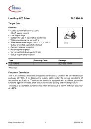
1.4 Pin Configuration<br />
•<br />
Figure 1<br />
Pin Configuration<br />
/VDDDET<br />
/RSTO<br />
VDDa_SR<br />
VSSa_SR<br />
XOUT<br />
XIN<br />
BOUT<br />
VDDa_UX<br />
VSSa_UX<br />
AOUT<br />
FSC<br />
DCL<br />
BUS<br />
VSSD<br />
VDDD<br />
TM2<br />
TM1<br />
/ACT<br />
22<br />
21<br />
20<br />
19<br />
18<br />
17<br />
16<br />
15<br />
14<br />
13<br />
12<br />
34<br />
35<br />
36<br />
37<br />
38<br />
39<br />
40<br />
41<br />
42<br />
43<br />
44<br />
11<br />
10<br />
9<br />
8<br />
7<br />
6<br />
5<br />
4<br />
3<br />
2<br />
1<br />
23<br />
24<br />
25<br />
26<br />
27<br />
28<br />
29<br />
30<br />
31<br />
32<br />
33<br />
VSSa_UR<br />
BIN<br />
/RST<br />
DIO<br />
VDDa_UR<br />
DD<br />
DU<br />
/LP2I<br />
SX1<br />
TP1<br />
VSSa_SX<br />
VDDa_SX<br />
SR1<br />
SR2<br />
SX2<br />
AIN<br />
TP2<br />
TM0<br />
VSSD<br />
VDDD<br />
T-SMINTO<br />
<strong>PEF</strong> <strong>80902</strong><br />
pin_2.vsd
<strong>PEF</strong> <strong>80902</strong><br />
Overview<br />
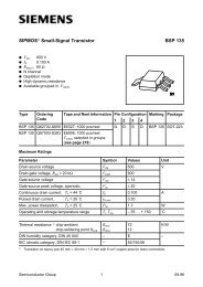
1.5 Block Diagram<br />
•<br />
XIN<br />
XOUT<br />
VDDDET<br />
RST RSTO<br />
SR1<br />
SR2<br />
Clock Generation<br />
POR/UVD<br />
AOUT<br />
BOUT<br />
SX1<br />
SX2<br />
S-Transceiver<br />
U-Tansceiver<br />
AIN<br />
BIN<br />
TM0<br />
TM1<br />
TM2<br />
Test Modes<br />
Factory Test<br />
LED<br />
TP1<br />
TP2<br />
ACT<br />
LP2I<br />
DIO<br />
IOM-2 Interface<br />
S Transceiver Control<br />
FSC<br />
DCL<br />
DU<br />
DD<br />
BUS<br />
block diagram.vsd<br />
Figure 2<br />
Block Diagram<br />
Data Sheet 6 2001-11-12
<strong>PEF</strong> <strong>80902</strong><br />
Overview<br />
1.6 Pin Definitions and Functions<br />
•<br />
Table 2<br />
Pin Definitions and Functions<br />
Pin Symbol Type Function<br />
2 VDDa_UR – Supply voltage for U-Receiver<br />
(3.3 V ± 5%)<br />
1 VSSa_UR – Analog ground (0 V) U-Receiver<br />
42 VDDa_UX – Supply voltage for U-Transmitter<br />
(3.3 V ± 5%)<br />
43 VSSa_UX – Analog ground (0 V) U-Transmitter<br />
36 VDDa_SR – Supply voltage for S-Receiver<br />
(3.3 V ± 5%)<br />
37 VSSa_SR – Analog ground (0 V) S-Receiver<br />
31 VDDa_SX – Supply voltage for S-Transmitter<br />
(3.3 V ± 5%)<br />
30 VSSa_SX – Analog ground (0 V) S-Transmitter<br />
19 VDDD – Supply voltage digital circuits<br />
(3.3 V ± 5%)<br />
20 VSSD – Ground (0 V) digital circuits<br />
8 VDDD – Supply voltage digital circuits<br />
(3.3 V ± 5%)<br />
9 VSSD – Ground (0 V) digital circuits<br />
22 FSC O Frame Sync:<br />
8-kHz frame synchronization signal<br />
21 DCL O Data Clock:<br />
IOM -2 interface clock signal (double clock):<br />
512 kHz<br />
25 LP2I O Loopback 2 indication:<br />
Can directly drive a LED (4mA).<br />
0: Loopback 2 closed<br />
1: Loopback 2 not closed.<br />
23 DD I/O Data Downstream:<br />
Data on the IOM -2 interface<br />
Data Sheet 7 2001-11-12
<strong>PEF</strong> <strong>80902</strong><br />
Overview<br />
Table 2 Pin Definitions and Functions (cont’d)<br />
Pin Symbol Type Function<br />
24 DU I/O Data Upstream:<br />
Data on the IOM -2 interface<br />
7 DIO I Disable IOM -2:<br />
1: FSC, DCL, DU and DD high Z<br />
0: FSC, DCL, DU and DD push-pull<br />
18 BUS I<br />
(PU)<br />
Bus mode on S-interface:<br />
1: passive S-bus (fixed timing)<br />
0: point-to-point / extended passive S-bus<br />
(adaptive timing)<br />
5 RST I Reset:<br />
Low active reset input. Schmitt-Trigger input<br />
with hysteresis of typical 360mV. Tie to ’1’ if not<br />
used.<br />
6 RSTO OD Reset Output:<br />
Low active reset output.<br />
13 TM0 I Test Mode 0.<br />
Selects test pattern (see Page 10).<br />
14 TM1 I Test Mode 1.<br />
Selects test pattern (see Page 10).<br />
15 TM2 I Test Mode 2.<br />
Selects test pattern (see Page 10).<br />
28 SX1 O S-Bus Transmitter Output (positive)<br />
29 SX2 O S-Bus Transmitter Output (negative)<br />
32 SR1 I S-Bus Receiver Input<br />
33 SR2 I S-Bus Receiver Input<br />
40 XIN I Crystal 1:<br />
Connected to a 15.36 MHz crystal<br />
39 XOUT O Crystal 2:<br />
Connected to a 15.36 MHz crystal<br />
Data Sheet 8 2001-11-12
<strong>PEF</strong> <strong>80902</strong><br />
Overview<br />
Table 2 Pin Definitions and Functions (cont’d)<br />
Pin Symbol Type Function<br />
44 AOUT O Differential U-interface Output<br />
41 BOUT O Differential U-interface Output<br />
3 AIN I Differential U-interface Input<br />
4 BIN I Differential U-interface Input<br />
34 VDDDET I VDD Detection:<br />
This pin selects if the V DD detection is active<br />
(’0’) and reset pulses are generated on pin<br />
RSTO or whether it is deactivated (’1’) and an<br />
external reset has to be applied on pin RST.<br />
12 ACT O Activation LED.<br />
Indicates the activation status of U- and S-<br />
transceiver. Can directly drive a LED (4mA).<br />
27 TP1 I Test Pin 1.<br />
Used for factory device test.<br />
Tie to ’V SS ’<br />
35 TP2 I Test Pin 2.<br />
Used for factory device test.<br />
Tie to ’V SS ’<br />
10,11,<br />
16,17,<br />
26,38<br />
Tie to ‘1‘<br />
PU: Internal pull-up resistor (typ. 100µA)<br />
I: Input<br />
O: Output (Push-Pull)<br />
OD: Output (Open Drain)<br />
1.6.1 Specific Pins and Test Modes<br />
LED Pins ACT, LP2I<br />
A LED can be connected to pin ACT to display four different states (off, slow flashing,<br />
fast flashing, on). It displays the activation status of the U- and S-transceiver according<br />
to Table 3.<br />
•<br />
Data Sheet 9 2001-11-12
<strong>PEF</strong> <strong>80902</strong><br />
Table 3 ACT States<br />
Pin ACT LED U_Deactivated U_Activated S_Activated<br />
V DD OFF 1 x x<br />
2Hz (1 : 1)* fast flashing 0 0 x<br />
1Hz (3 : 1)* slow flashing 0 1 0<br />
GND ON 0 1 1<br />
Note: * denotes the duty cycle ’high’ : ’low’.<br />
Overview<br />
with:<br />
U_Deactivated: ’Deactivated State’ as defined in Chapter 2.3.7.6.<br />
U_Activated: ’SBC Synchronizing’, ’Wait for Info U4H’, and ‘Transparent‘ as defined in<br />
Chapter 2.3.7.6.<br />
S-Activated: ’Activated State’ as defined in Chapter 2.4.5.1.<br />
Note: Optionally, pin ACT can drive a second LED with inverse polarity (connect this<br />
additional LED to 3.3V only).<br />
Another LED can be connected to pin LP2I to indicate an active Loopback 2 according<br />
to Table 4.<br />
Table 4 LP2I States<br />
Pin LP2I LED Loopback 2 command in the C L -channel<br />
V DD off received no loopback 2 command or loopback deactivation<br />
after a loopback 2 command.<br />
GND on Loopback 2 command has been received. Complete analog<br />
loop is being closed on the S-interface.<br />
Test Modes<br />
Different test patterns on the U- and S-interface can be generated via pins TM0-2<br />
according to Table 5.<br />
Table 5 Test Modes<br />
TM0 TM1 TM2 U-transceiver S-transceiver<br />
0 0 0 Reserved for future use. Normal operation in this<br />
0 0 1 version.<br />
0 1 0 Normal operation 96 kHz 1)<br />
Continuous Pulses<br />
0 1 1 2 kHz 2) Single Pulses<br />
Data Sheet 10 2001-11-12
<strong>PEF</strong> <strong>80902</strong><br />
Table 5 Test Modes (cont’d)<br />
TM0 TM1 TM2 U-transceiver S-transceiver<br />
1)<br />
2)<br />
3)<br />
4)<br />
1 0 0 Data Through 3) Normal operation<br />
1 0 1 Send Single Pulses 4)<br />
1 1 0 Quiet Mode 5)<br />
1 1 1 normal operation<br />
Overview<br />
The S-transceiver transmits pulses with alternating polarity at a rate of 192 kHz resulting in a 96 kHz envelope.<br />
The S-transceiver transmits pulses with alternating polarity at a rate of 4 kHz resulting in a 2 kHz envelope.<br />
Forces the U-transceiver into the state ’Transparent’ where it transmits signal U5.<br />
Forces the U-transceiver to go into state ’Test’ and to send single pulses. The pulses are issued at 1.0 ms<br />
intervals and have a duration of 8.33 µs.<br />
5)<br />
The U-transceiver is hardware reset.<br />
1.7 System Integration<br />
The T-SMINT O provides NT1 functionality without a microcontroller being necessary.<br />
Special selections can be done via pin strapping (DIO, BUS, TM0-2). The device has no<br />
µP interface.<br />
The IOM -2 Interface serves only for monitoring and debugging purposes. It can be<br />
regarded as a window to the internal IOM -2.<br />
.<br />
Data Sheet 11 2001-11-12
<strong>PEF</strong> <strong>80902</strong><br />
Overview<br />
•<br />
DC/DC-Converter<br />
IDCC<br />
PEB2023<br />
S/T - Interface<br />
S<br />
T-SMINTO<br />
<strong>PEF</strong><strong>80902</strong><br />
U<br />
U - Interface<br />
IOM-2<br />
LEDs<br />
Pin Strap - Mode Selection<br />
- Loop 2 Ind.<br />
- Activation<br />
Status<br />
- Disable IOM - 2<br />
- P - to - P / Bus Selection<br />
- Test Pattern Selection<br />
NT1_appl.vsd<br />
Figure 3<br />
Application Example T-SMINT O: Standard NT1<br />
Data Sheet 12 2001-11-12
<strong>PEF</strong> <strong>80902</strong><br />
Functional Description<br />
2 Functional Description<br />
2.1 Reset Generation<br />
External Reset Input<br />
At the RST input an external reset can be applied forcing the T-SMINT O in the reset<br />
state. This external reset signal is additionally fed to the RSTO output.<br />
Reset Ouput<br />
If VDDDET is active, then the deactivation of a reset output on RSTO is delayed by<br />
t DEACT (see Table 28).<br />
Reset Generation<br />
The T-SMINT O has an on-chip reset generator based on a Power-On Reset (POR) and<br />
Under Voltage Detection (UVD) circuit (see Table 28). The POR/UVD requires no<br />
external components.<br />
The POR/UVD circuit can be disabled via pin VDDDET.<br />
The requirements on V DD ramp-up during power-on reset are described in<br />
Chapter 4.6.3.<br />
Clocks and Data Lines During Reset<br />
During reset the data clock (DCL) and the frame synchronization (FSC) keep running.<br />
During reset DD and DU are high; with the exception of:<br />
• The output C/I code from the U-Transceiver on DD is ’DR’ = 0000<br />
• The output C/I code from the S-Transceiver on DU is ’TIM’ = 0000.<br />
Data Sheet 13 2001-11-12
<strong>PEF</strong> <strong>80902</strong><br />
2.2 IOM ® -2 Interface<br />
Functional Description<br />
The IOM -2 interface always operates in NT mode according to the IOM -2 Reference<br />
Guide [12].<br />
2.2.1 IOM -2 Functional Description<br />
The IOM -2 interface consists of four lines: FSC, DCL, DD, DU. The rising edge of FSC<br />
indicates the start of an IOM -2 frame. The DCL clock signal synchronizes the data<br />
transfer on both data lines DU and DD. The DCL is twice the bit rate. The bits are shifted<br />
out with the rising edge of the first DCL clock cycle.<br />
Note: It is not possible to write any data via IOM -2 into the T-SMINT O.<br />
The IOM -2 interface can be enabled/disabled with pin DIO.<br />
The FSC signal is an 8 kHz frame sync signal. The number of PCM timeslots on the<br />
transmit line is determined by the frequency of the DCL clock , with the 512 kHz clock 1<br />
channel consisting of 4 timeslots is available.<br />
IOM ® -2 Frame Structure of the T-SMINT O<br />
The frame structure on the IOM -2 data ports (DU,DD) of the T-SMINT O with a DCL<br />
clock of 512 kHz is shown in Figure 4.<br />
•<br />
macro_19_QSMINTO<br />
Figure 4<br />
IOM ® -2 Frame Structure of the T-SMINT O<br />
The frame is composed of one channel:<br />
• Channel 0 contains 144-kbit/s of user and signaling data (2B + D), a MONITOR<br />
programming channel (not available in T-SMINT O) and a command/indication<br />
channel (CI0) for control of e.g. the U-transceiver.<br />
Data Sheet 14 2001-11-12
<strong>PEF</strong> <strong>80902</strong><br />
2.3 U-Transceiver<br />
Functional Description<br />
The statemachine of the U-Transceiver is compatible to the NT state machine in the PEB<br />
8090 documentation [9], but includes some minor changes for simplification and<br />
compliance to Ref. [1].<br />
Basic configurations are selected via pin strapping<br />
2.3.1 4B3T Frame Structure<br />
The 4B3T U-interface performs full duplex data transmission and reception at the U-<br />
reference point according to ETSI TS 102 080 and FTZ 1TR 220. It applies the 4B3T<br />
block code together with adaptive echo cancelling and equalization. Transmission<br />
performance shall be such, that it meets all ETSI and FTZ test loops with margin.<br />
The U-interface is designed for data transmission on twisted pair wires in local telephone<br />
loops, with basic access to ISDN and a user bit rate of 144 kbit/s.<br />
The following information is transmitted over the twisted pair:<br />
• Bidirectional:<br />
– B1, B2, D data channels<br />
– 120 kHz Symbol clock<br />
– 1 kHz Frame<br />
– Activation<br />
– 1 kbit/s Transparent Channel (M symbol), (not implemented)<br />
• From LT to NT side:<br />
– Power feeding<br />
– Deactivation<br />
– Remote control of test loops (M symbol)<br />
• From NT to LT side:<br />
– Indication of monitored code violations (M symbol)<br />
Performance Requirements according to FTZ 1 TR 220 (August 1991):<br />
On the U-interface, the following transmission ranges are achieved without additional<br />
signal regeneration on the loop (bit error rate ≤ 10 -7 ):<br />
• with noise: ≥ 4.2 km on wires of 0.4 mm diameter and ≥ 8 km on 0.6 mm wires<br />
• without noise: ≥ 5 km on wires of 0.4 mm diameter and ≥ 10 km on 0.6 mm wires<br />
Note: Typical attenuation of FTZ wires of 0.4 mm diameter is about 7dB/km in contrast<br />
to ETSI wires of 0.4 mm with about 8dB/km.<br />
The transmission ranges can be doubled by inserting a repeater for signal regeneration.<br />
Performance requirements according to ETSI TS 102 080 are met, too.<br />
1 ms frames are transmitted via the U-interface, each consisting of:<br />
• 108 symbols: 144 bit scrambled and coded B1 + B2 + D data<br />
Data Sheet 15 2001-11-12
<strong>PEF</strong> <strong>80902</strong><br />
Functional Description<br />
• 11 symbols: Barker code for both symbol and frame synchronization (not scrambled)<br />
• 1 symbol: Ternary maintenance symbol (not scrambled)<br />
The 108 user data symbols are split into four equally structured groups. Each group<br />
(27 ternary symbols, resp. 36 bits) contains the user data of two IOM ® -2 frames in the<br />
same order (8B + 8B + 2D + 8B + 8B + 2D).<br />
Different syncwords are used for each direction:<br />
• Downstream from LT to NT + + + – – – + – – + –<br />
• Upstream from NT to LT – + – – + – – – + + +<br />
On the NT side, the transmitted Barker code begins 60 symbols after the received Barker<br />
code and vice versa.<br />
Table 6 Frame Structure A for Downstream Transmission LT to NT<br />
1 2 3 4 5 6 7 8 9 10 11 12<br />
D 1 D 1 D 1 D 1 D 1 D 1 D 1 D 1 D 1 D 1 D 1 D 1<br />
13 14 15 16 17 18 19 20 21 22 23 24<br />
D 1/2 D 1/2 D 1/2 D 2 D 2 D 2 D 2 D 2 D 2 D 2 D 2 D 2<br />
25 26 27 28 29 30 31 32 33 34 35 36<br />
D 2 D 2 D 2 D 3 D 3 D 3 D 3 D 3 D 3 D 3 D 3 D 3<br />
37 38 39 40 41 42 43 44 45 46 47 48<br />
D 3 D 3 D 3 D 3/4 D 3/4 D 3/4 D 4 D 4 D 4 D 4 D 4 D 4<br />
49 50 51 52 53 54 55 56 57 58 59 60<br />
D 4 D 4 D 4 D 4 D 4 D 4 D 5 D 5 D 5 D 5 D 5 D 5<br />
61 62 63 64 65 66 67 68 69 70 71 72<br />
D 5 D 5 D 5 D 5 D 5 D 5 D 5/6 D 5/6 D 5/6 D 6 D 6 D 6<br />
73 74 75 76 77 78 79 80 81 82 83 84<br />
D 6 D 6 D 6 D 6 D 6 D 6 D 6 D 6 D 6 D 7 D 7 D 7<br />
85 86 87 88 89 90 91 92 93 94 95 96<br />
M D 7 D 7 D 7 D 7 D 7 D 7 D 7 D 7 D 7 D 7/8 D 7/8<br />
97 98 99 100 101 102 103 104 105 106 107 108<br />
D 7/8 D 8 D 8 D 8 D 8 D 8 D 8 D 8 D 8 D 8 D 8 D 8<br />
109 110 111 112 113 114 115 116 117 118 119 120<br />
D 8 + + + – – – + – – + –<br />
Data Sheet 16 2001-11-12
<strong>PEF</strong> <strong>80902</strong><br />
Functional Description<br />
D 1 ... D 8 Ternary 2B + D data of IOM ® -2 frames 1 ... 8<br />
M<br />
Maintenance symbol<br />
+, – Syncword<br />
Data Sheet 17 2001-11-12
<strong>PEF</strong> <strong>80902</strong><br />
Functional Description<br />
•<br />
Table 7<br />
Frame Structure B for Upstream Transmission NT to LT<br />
1 2 3 4 5 6 7 8 9 10 11 12<br />
U 1 U 1 U 1 U 1 U 1 U 1 U 1 U 1 U 1 U 1 U 1 U 1<br />
13 14 15 16 17 18 19 20 21 22 23 24<br />
U 1/2 U 1/2 U 1/2 U 2 U 2 U 2 U 2 U 2 U 2 U 2 U 2 U 2<br />
25 26 27 28 29 30 31 32 33 34 35 36<br />
M U 2 U 2 U 2 U 3 U 3 U 3 U 3 U 3 U 3 U 3 U 3<br />
37 38 39 40 41 42 43 44 45 46 47 48<br />
U 3 U 3 U 3 U 3 U 3/4 U 3/4 U 3/4 U 4 U 4 U 4 U 4 U 4<br />
49 50 51 52 53 54 55 56 57 58 59 60<br />
U 4 – + – – + – – – + + +<br />
61 62 63 64 65 66 67 68 69 70 71 72<br />
U 4 U 4 U 4 U 4 U 4 U 4 U 5 U 5 U 5 U 5 U 5 U 5<br />
73 74 75 76 77 78 79 80 81 82 83 84<br />
U 5 U 5 U 5 U 5 U 5 U 5 U 5/6 U 5/6 U 5/6 U 6 U 6 U 6<br />
85 86 87 88 89 90 91 92 93 94 95 96<br />
U 6 U 6 U 6 U 6 U 6 U 6 U 6 U 6 U 6 U 7 U 7 U 7<br />
97 98 99 100 101 102 103 104 105 106 107 108<br />
U 7 U 7 U 7 U 7 U 7 U 7 U 7 U 7 U 7 U 7/8 U 7/8 U 7/8<br />
109 110 111 112 113 114 115 116 117 118 119 120<br />
U 8 U 8 U 8 U 8 U 8 U 8 U 8 U 8 U 8 U 8 U 8 U 8<br />
U 1 ... U 8 Ternary 2B + D data of IOM ® -2 frames 1... 8<br />
M<br />
Maintenance symbol<br />
+, - Syncword<br />
Data Sheet 18 2001-11-12
<strong>PEF</strong> <strong>80902</strong><br />
2.3.2 Maintenance Channel<br />
Functional Description<br />
The 4B3T frame structure provides a 1 kbit/s M(aintenance)-channel for the transfer of<br />
remote loopback commands and error indications.<br />
Loopback Commands<br />
The LT station uses the M-channel to request remote loopbacks. Loopback commands<br />
are coded with a series of ’0’ and ’+’ symbols.<br />
• A continuous series of ’+’ requests for loopback 2 activation in the NT<br />
• A continuous series of ’0’ requests for deactivation of any loopback<br />
The NT station reacts as soon as the pattern has been detected in 8 consecutive<br />
symbols.<br />
Error Indications<br />
The NT U-transceiver reports line code violations via the M-channel to the exchange by<br />
setting one M-Bit to ’+’ polarity.<br />
Transparent Messages<br />
The exchange of Transparent Messages via the Transparent Channel is not supported<br />
by the T-SMINTO.<br />
2.3.3 Coding from Binary to Ternary Data<br />
Each 4 bit block of binary data is coded into 3 ternary symbols of MMS 43 block code<br />
according to Table 8.<br />
The number of the next column to be used, is given at the right hand side of each block.<br />
The left hand signal elements in the table (both ternary and binary) are transmitted first.<br />
•<br />
Table 8<br />
MMS 43 Coding Table<br />
S1 S2 S3 S4<br />
t → t → t → t → t →<br />
0 0 0 1 0 – + 1 0 – + 2 0 – + 3 0 – + 4<br />
0 1 1 1 – 0 + 1 – 0 + 2 – 0 + 3 – 0 + 4<br />
0 1 0 0 – + 0 1 – + 0 2 – + 0 3 – + 0 4<br />
0 0 1 0 + – 0 1 + – 0 2 + – 0 3 + – 0 4<br />
1 0 1 1 + 0 – 1 + 0 – 2 + 0 – 3 + 0 – 4<br />
1 1 1 0 0 + – 1 0 + – 2 0 + – 3 0 + – 4<br />
1 0 0 1 + – + 2 + – + 3 + – + 4 – – – 1<br />
Data Sheet 19 2001-11-12
<strong>PEF</strong> <strong>80902</strong><br />
Table 8<br />
MMS 43 Coding Table (cont’d)<br />
2.3.4 Decoding from Ternary to Binary Data<br />
Functional Description<br />
S1 S2 S3 S4<br />
0 0 1 1 0 0 + 2 0 0 + 3 0 0 + 4 – – 0 2<br />
1 1 0 1 0 + 0 2 0 + 0 3 0 + 0 4 – 0 – 2<br />
1 0 0 0 + 0 0 2 + 0 0 3 + 0 0 4 0 – – 2<br />
0 1 1 0 – + + 2 – + + 3 – – + 2 – – + 3<br />
1 0 1 0 + + – 2 + + – 3 + – – 2 + – – 3<br />
1 1 1 1 + + 0 3 0 0 – 1 0 0 – 2 0 0 – 3<br />
0 0 0 0 + 0 + 3 0 – 0 1 0 – 0 2 0 – 0 3<br />
0 1 0 1 0 + + 3 – 0 0 1 – 0 0 2 – 0 0 3<br />
1 1 0 0 + + + 4 – + – 1 – + – 2 – + – 3<br />
Decoding is done in the reverse manner of coding. The received blocks of 3 ternary<br />
symbols are converted into blocks of 4 bits. The decoding algorithm is given in Table 9.<br />
As in the encoding table, the left hand symbol of each block (both binary and ternary) is<br />
the first bit and the right hand is the last. If a ternary block "0 0 0" is received, it is decoded<br />
to binary "0 0 0 0". This pattern usually occurs only during deactivation.<br />
•<br />
Table 9<br />
4B3T Decoding Table<br />
Ternary Block<br />
Binary Block<br />
0 0 0, + 0 +, 0 – 0 0 0 0 0<br />
0 – + 0 0 0 1<br />
+ – 0 0 0 1 0<br />
0 0 +, – – 0 0 0 1 1<br />
– + 0 0 1 0 0<br />
0 + +, – 0 0 0 1 0 1<br />
– + +, – – + 0 1 1 0<br />
– 0 + 0 1 1 1<br />
+ 0 0, 0 – – 1 0 0 0<br />
+ – +, – – – 1 0 0 1<br />
+ + –, + – – 1 0 1 0<br />
+ 0 – 1 0 1 1<br />
+ + +, – + – 1 1 0 0<br />
Data Sheet 20 2001-11-12
<strong>PEF</strong> <strong>80902</strong><br />
Table 9<br />
4B3T Decoding Table (cont’d)<br />
2.3.4.1 Monitoring of Code Violations<br />
Functional Description<br />
0 + 0, – 0 – 1 1 0 1<br />
0 + – 1 1 1 0<br />
+ + 0, 0 0 – 1 1 1 1<br />
The running digital sum monitor (RDSM) computes the running digital sum from the<br />
received ternary symbols by adding the polarity of the received user data (+ 1, 0, –1). At<br />
the end of each block, the running digital sum is supposed to reflect the number of the<br />
next column in Table 8.<br />
A code violation has occurred if the running digital sum is less than one or more than four<br />
at the end of a ternary block, or if the ternary block 0 0 0 (three user symbols with zero<br />
polarity) is found in the received data.<br />
If at the end of a ternary block no error was found, the running digital sum retains its<br />
current value. If the counter value is greater than 4, it is set to 4 at the beginning of the<br />
next ternary block, if its value is 0 or less, it is set to one. So after a code violation has<br />
been detected, the RDSM synchronizes itself within a period depending on the received<br />
data pattern. Note there are some transmission errors which do not cause a code<br />
violation.<br />
2.3.5 Scrambler / Descrambler<br />
Scrambler<br />
The binary transmit data from the IOM ® -2 interface is scrambled with a polynomial of<br />
23 bits, before it is sent to the 4B3T coder. The scrambler polynomial is::<br />
z – 23 + z – 18 + 1<br />
Descrambler<br />
The received data (after decoding from ternary to binary) is multiplied with a polynomial<br />
of 23 bits in order to recover the original data before it is forwarded to the IOM ® -2<br />
interface.The descrambler is self synchronized after 23 symbols. The descrambler<br />
polynomial is::<br />
z – 23 + z – 5 + 1<br />
The scrambling / descrambling process is controlled fully by the T-SMINTO. Hence, no<br />
influence can be taken by the user.<br />
Data Sheet 21 2001-11-12
<strong>PEF</strong> <strong>80902</strong><br />
Functional Description<br />
2.3.6 Command/Indication Codes<br />
Both commands and indications depend on the data direction. Table 10 presents all<br />
defined C/I codes. A new command or indication will be recognized as valid after it has<br />
been detected in two successive IOM ® -2 frames (double last-look criterion).<br />
Indications are strictly state orientated. Refer to the state diagrams in the following<br />
sections for commands and indications applicable in various states.<br />
Table 10<br />
C/I Codes<br />
Code IN OUT<br />
0000 TIM DR<br />
0001 – –<br />
0010 – –<br />
0011 LTD –<br />
0100 – RSY<br />
0101 SSP –<br />
0110 DT –<br />
0111 – –<br />
1000 AR AR<br />
1001 reserved 1)<br />
–<br />
1010 – ARL<br />
1011 – –<br />
1100 AI AI<br />
1101 RES –<br />
1110 – AIL<br />
1111 DI DC<br />
1)<br />
C/I code ‘1010‘ must not be input to the U-transceiver.<br />
•<br />
AI Activation Indication DI Deactivation Indication.<br />
AIL Activation Indication Loop 2 DR Deactivation Request<br />
AR Activation Request LTD LT Disable<br />
ARL Activation Request Local Loop RES Reset<br />
DT Data Through Mode RSY Resynchronization Indication<br />
Data Sheet 22 2001-11-12
<strong>PEF</strong> <strong>80902</strong><br />
Functional Description<br />
DC Deactivation Confirmation SSP Send-Single-Pulses<br />
TIM Timing Request<br />
2.3.7 State Machine for Activation and Deactivation<br />
2.3.7.1 State Machine Notation<br />
The following state diagram describes all the actions/reactions resulting from any<br />
command or detected signal and resulting from the various operating modes.<br />
The states with its inputs and outputs are interpreted as shown below:<br />
Transmitted U-Signal<br />
State Name<br />
C/I Channel Indication<br />
(DOUT)<br />
OUT<br />
SM_expl.emf<br />
Figure 5<br />
State Diagram Example<br />
Each state has one or more transitions to other states. These transitions depend on<br />
certain conditions which are noted next to the transition lines. These conditions are the<br />
only possibility to leave a state. If more conditions have to be fulfilled together, they are<br />
put into parentheses with an AND operator (&). If more than one condition leads to the<br />
same transition, they are put into parentheses with an OR operator (|). The meaning of<br />
a condition may be inverted by the NOT operator (/). Only the described states and<br />
transitions exist.<br />
At some transitions, an internal timer is started. The start of a timer is indicated by TxS<br />
(’x’ is the timer number). Transitions that are caused if a timer has expired are labelled<br />
by TxE.<br />
Some conditions lead to the same target state. To reduce the number of lines and the<br />
complexity of the figures, a state named “ANY STATE” acts on behalf of all state.<br />
Data Sheet 23 2001-11-12
<strong>PEF</strong> <strong>80902</strong><br />
Functional Description<br />
The state machines are designed to cope with all ISDN devices with IOM ® -2 standard<br />
interfaces. Undefined situations are excluded. In any case, the involved devices will<br />
enter defined conditions as soon as the line is deactivated.<br />
2.3.7.2 Awake Protocol<br />
For the awake process two signals are defined’ U1W’ and ’U2W’. Depending on the call<br />
direction (up-, downstream) U1W and U2W are interpreted as awake or acknowledge<br />
signals (see figures below).<br />
•<br />
12 ms<br />
7 ms<br />
LT<br />
INFO U2W<br />
2.133 ms<br />
INFO U2 (A)<br />
13 ms<br />
NT<br />
INFO U1W<br />
2.133 ms<br />
INFO U1A<br />
ITD06385.vsd<br />
Figure 6<br />
Awake Procedure initiated by the LT<br />
•<br />
6 ms<br />
7 ms<br />
LT<br />
INFO U2W<br />
2.133 ms<br />
INFO U2 (A)<br />
13 ms<br />
NT<br />
INFO U1W<br />
2.133 ms<br />
INFO U1A<br />
ITD06386.vsd<br />
Figure 7<br />
Awake Procedure initiated by the NT<br />
Data Sheet 24 2001-11-12
<strong>PEF</strong> <strong>80902</strong><br />
Functional Description<br />
Acting as Calling Station<br />
After sending the awake signal, the awaking U-transceiver waits for the acknowledge.<br />
After 12 ms, the awake signal is repeated, if no acknowledge has been recognized.<br />
If an acknowledge signal has been recognized, the U-transceiver waits for its possible<br />
repetition (in case of previous coincidence of two awake signals). If no repetition was<br />
detected, the U-transceiver starts transmitting U2 with a delay of 7 ms.<br />
If such a repetition is detected, the U-transceiver interprets it as an awake signal and<br />
behaves like a device awoken by the far end.<br />
Acknowledging a Wake-Up Call<br />
If a deactivated device detects an awake signal on U, an acknowledge signal is sent out.<br />
After that, the U-transceiver waits for a possible repetition of the awake signal (in case<br />
the acknowledge hasn’t been recognized).<br />
If no repetition is found, the awoken U-transceiver starts sending U2 after 7 ms from<br />
detecting the awake signal. If a repeated awake signal is found, the procedure in the<br />
awoken U-transceiver starts again.<br />
Data Sheet 25 2001-11-12
<strong>PEF</strong> <strong>80902</strong><br />
2.3.7.3 NT State Machine (IEC-T / NTC-T Compatible)<br />
Functional Description<br />
•<br />
AWR<br />
U0<br />
IOM Awaked<br />
DC<br />
AR<br />
DI<br />
TIM<br />
AR<br />
U0<br />
Deactivated<br />
DC U0, DA<br />
AWR<br />
T6S<br />
U1W<br />
Start Awaking Uk0<br />
RSY<br />
T6S<br />
AWT<br />
T6S<br />
T05S<br />
T05S<br />
T05E<br />
U0<br />
Deactivating<br />
DC<br />
AWR<br />
T6E<br />
U0<br />
Awake Signal Sent<br />
RSY<br />
AWR<br />
T13S<br />
T13E<br />
U0<br />
Ack. Sent / Received<br />
RSY<br />
AWR<br />
(DI & T05E)<br />
AWT<br />
T13S<br />
U1W<br />
Sending Awake-Ack.<br />
RSY<br />
T13S<br />
T12S<br />
U1A<br />
Synchronizing<br />
RSY<br />
(U0 & T12E)<br />
T05S<br />
U0<br />
Pend. Deactivation<br />
DR<br />
DI<br />
SP / U0<br />
Test<br />
DR<br />
U2<br />
T05S<br />
SSP or LTD<br />
U1<br />
SBC Synchronizing<br />
AR / ARL<br />
AI<br />
U3<br />
Wait for Info U4H<br />
AR / ARL<br />
U0<br />
LOF<br />
U0<br />
LOF<br />
DT<br />
DI<br />
ANY STATE<br />
RES<br />
U0<br />
Reset<br />
DR<br />
U4H<br />
U5<br />
Transparent<br />
AI / AIL<br />
U0<br />
LOF<br />
U0<br />
Loss of Framing<br />
RSY<br />
U0<br />
NT_SM_4B3T_cust.emf<br />
Figure 8<br />
NT State Machine (IEC-T/NTC-T Compatible)<br />
Note: The test modes ’Data Through‘ (DT), ‘Send Single Pulses‘ (SSP) and ‘Quiet Mode‘<br />
(QM) can be generated via pins TM0-2 according to Table 5.<br />
Data Sheet 26 2001-11-12
<strong>PEF</strong> <strong>80902</strong><br />
Functional Description<br />
•<br />
Table 11 Differences to the former NT-SM of the IEC-T/NTC-T<br />
No. State/ Signal Change Comment<br />
1. State ’Deact.<br />
Request Rec.’<br />
2. State ’Loss of<br />
Framing’<br />
split into 3 states<br />
- ’Pend. Deactivation 1’<br />
- ’Reset’ State<br />
- ’Test’ State<br />
3. C/I-code LTD new inserted<br />
4. State<br />
’Power Down’<br />
5. State<br />
’Data<br />
Transmission’<br />
6. Timer<br />
variables<br />
introduced<br />
new inserted,<br />
results in different behavior<br />
in state ’Transparent’,<br />
no return to normal<br />
transmission possible after<br />
detection of LOF<br />
renamed to state<br />
’Deactivated’<br />
renamed to state<br />
’Transparent’<br />
Name Duration see Table 12<br />
simplifies SM implementation<br />
compliance to ETSI TS 102 080,<br />
corresponds to state NT1.10<br />
for consistency reasons to 2B1Q<br />
2.3.7.4 Inputs to the U-Transceiver<br />
C/I-Commands<br />
AI Activation Indication<br />
The downstream device issues this indication to announce that layer 1 is<br />
available. The U-transceiver in turn informs the LT side by transmitting U3.<br />
AR<br />
DI<br />
DT<br />
Activation Request<br />
The U-transceiver is requested to start the activation process (if not already<br />
done) by sending the wake-up signal U1W.<br />
Deactivation Indication<br />
This indication is used during a deactivation procedure to inform the U-<br />
transceiver that it may enter the ’Deactivated’ (power-down) state.<br />
Data Through Test Mode<br />
This unconditional command is used for test purposes only and forces the U-<br />
transceiver into state ’Transparent’.<br />
Data Sheet 27 2001-11-12
<strong>PEF</strong> <strong>80902</strong><br />
Functional Description<br />
LTD<br />
RES<br />
SSP<br />
TIM<br />
LT Disable<br />
This unconditional command forces the U-transceiver to state ’Test’, where it<br />
transmits U0. No further action is initiated.<br />
Reset<br />
Unconditional command which resets the U-transceiver.<br />
Send Single Pulses<br />
Unconditional command which requests the transmission of single pulses on<br />
the U-interface.<br />
Timing<br />
The U-transceiver is requested to enter state ’IOM Awaked’.<br />
U-Interface Events<br />
U0 U0 detected<br />
U0 is recognized after 120 symbols (1ms) with zero level in a row. Detection<br />
may last up to 2 ms.<br />
U2<br />
U4H<br />
AWR<br />
AWT<br />
LOF<br />
TxE<br />
U2 detected<br />
The U-transceiver detects U2 if continuous binary 0‘s are found after<br />
descrambling and LOF = 0 for at least 8 subsequent U-frames. U2 is detected<br />
after 8 to 9 ms.<br />
U4H detected<br />
U4H is recognized, if the U-transceiver detects 16 subsequent binary 1’s after<br />
descrambling.<br />
Awake signal (U2W) detected<br />
Awake signal (U1W) has been sent out<br />
Loss of Framing on U-interface<br />
Timer ended, the started timer has expired<br />
Timers<br />
The start of timers is indicated by TxS, the expiry by TxE. The following table shows<br />
which timers are used.<br />
•<br />
Table 12<br />
Timers<br />
Timer Duration (ms) Function State<br />
T05 0.5 C/I code recognition Pend. Deactivation,<br />
Deactivating<br />
T6 6 Supervises U1W repetition Start Awaking Uk0<br />
Data Sheet 28 2001-11-12
<strong>PEF</strong> <strong>80902</strong><br />
Table 12 Timers (cont’d)<br />
Timer Duration (ms) Function State<br />
T12 12 Prevents the U-transceiver in<br />
state Synchronizing from<br />
immediate transition to state<br />
’Pend. Deactivation’ if U0 is<br />
detected<br />
2.3.7.5 Outputs of the U-Transceiver<br />
Functional Description<br />
Below the signals and indications are summarized that are issued on IOM ® -2 (C/I<br />
indications) and on the U-interface (predefined U-signals).<br />
C/I Indications<br />
AI Activation Indication<br />
The U-transceiver has established transparency of transmission. The<br />
downstream device is requested to establish layer-1 functionality.<br />
AIL<br />
AR<br />
ARL<br />
DC<br />
DR<br />
RSY<br />
Activation Indication Loop-back<br />
The U-transceiver has established transparency of transmission. The<br />
downstream device is requested to establish a loopback #2.<br />
Activation Request<br />
The downstream device is requested to start the activation procedure.<br />
Activation Request Loop-back<br />
The U-transceiver has detected a loop-back 2 command in the M-channel and<br />
has established transparency of transmission in the direction IOM ® to U-<br />
interface. The downstream device is requested to start the activation<br />
procedure and to establish a loopback #2.<br />
Deactivation Confirmation<br />
Idle code on the IOM ® -2 interface.<br />
Synchronizing<br />
T13 13 Supervises U2W repetition Ack. sent / received<br />
Sending awake-ack.<br />
Deactivation Request<br />
The U-transceiver has detected a deactivation request command from the LTside<br />
for a complete deactivation. The downstream device is requested to start<br />
the deactivation procedure.<br />
Resynchronizing Indication<br />
RSY informs the downstream device that the U-transceiver is not<br />
synchronous.<br />
Data Sheet 29 2001-11-12
<strong>PEF</strong> <strong>80902</strong><br />
Functional Description<br />
Signals on U-Interface<br />
The signals U0, U1W, U1A, U1, U3, U5 and SP are transmitted on the U-interface.They<br />
are defined in Table 17.<br />
Signals on IOM ® -2<br />
The Data (B+B+D) is set to all ’1’s in all states besides the states listed in Table 13.<br />
•<br />
Table 13<br />
SBC Sychronizing<br />
Wait for INFO U4H<br />
Transparent<br />
Active States<br />
Dependence of Outputs<br />
The M-symbol output in states with valid M-symbol output its value is set according to<br />
Table 14<br />
•:<br />
Table 14<br />
M Symbol Output<br />
RDS Error not detected detected<br />
M Symbol Output ’0’ ’+’<br />
•<br />
Table 15<br />
Signal Output on Uk0 in State Test<br />
Input SSP active all other except C/I-Code ’DI’<br />
Signal Output on SP<br />
U0<br />
Uk0<br />
•<br />
Table 16 C/I-Code Output<br />
Loopback<br />
SBC Wait for Info U4H Transparent<br />
Command Synchronizing<br />
not received AR AR AI<br />
received ARL ARL AIL<br />
2.3.7.6 NT-States<br />
In this section each state is described with its function.<br />
Data Sheet 30 2001-11-12
<strong>PEF</strong> <strong>80902</strong><br />
Functional Description<br />
Acknowledge Sent / Receive<br />
After having sent the awake signal, the U-transceiver has received the acknowledge<br />
wake tone. If being awoken the U-transceiver has sent the acknowledge. In both cases<br />
the U-transceiver waits for possible repetition or time-out.<br />
Awake Signal Sent<br />
The NT has sent out the awake signal U1W and waits now for a response. If the LT does<br />
not react in time timer T6 expires and the NT repeats its wake-up call.<br />
Deactivated<br />
Only in “Deactivated” state the device may enter the power-down mode.<br />
Deactivating<br />
State Deactivating assures that the C/I-channel code DC is issued four times before<br />
entering the ’Deactivated’ state.<br />
IOM ® Awaked<br />
The U-transceiver is deactivated, but may not enter the power-down mode.<br />
Loss of Framing<br />
This state is entered on loss of framing (LOF). No signal is transmitted on the U-interface.<br />
A receiver-reset is performed by.<br />
Note that there is no return to the ’Transparent’ state that has been possible before in<br />
the former IEC-T based state machine.<br />
Pending Deactivation<br />
The U-transceiver has received U0. The U-transceiver remains at least 0.5ms in this<br />
state before it accepts DI.<br />
SBC Synchronizing<br />
The NT is now synchronized and indicates this by AR/ARL towards the downstream<br />
device. The NT waits for the acknowledge ’AI’ from the downstream device.<br />
Sending Awake-Ack.<br />
On the receipt of the awake signal U2W the U-transceiver responds with the<br />
transmission of U1W.<br />
Data Sheet 31 2001-11-12
<strong>PEF</strong> <strong>80902</strong><br />
Functional Description<br />
Start Awaking Uk0<br />
On the receipt of AR in the C/I-channel the U-transceiver sends the awake signal U1W<br />
to start an activation.<br />
Synchronizing<br />
After the successful awake procedure the U-transceiver trains its receiver coefficients<br />
until it is able to detect the signals U2.<br />
Reset<br />
In state ’Reset’ a software-reset is performed.<br />
Test<br />
State “Test” is entered when the unconditional commands TM2-0=’SSP’ is applied. The<br />
test signal SSP is issued as long as pin SSP is active or C/I=SSP is applied.<br />
Transparent<br />
The transmission line is fully activated. User data is transparently exchanged by U4/U5.<br />
Transparent state is entered in the case of a loopback 2. The downstream device is<br />
informed by C/I code AI that the transparent state has been reached<br />
Note that in contrast to the former IEC-T state machine there is no resynchronization<br />
mechanism. Once loss of framing (LOF) has been detected a deactivation is initiated.<br />
Wait for Info U4H<br />
The NT is synchronized and waits now for the permission (U4H) to go to the<br />
’Transparent’ state.<br />
Data Sheet 32 2001-11-12
<strong>PEF</strong> <strong>80902</strong><br />
2.4 S-Transceiver<br />
Functional Description<br />
The S-Transceiver offers the NT state machine described in the User’s Manual V3.4 [8].<br />
The S-transceiver basic configurations are performed via pin strapping.<br />
2.4.1 Line Coding, Frame Structure<br />
Line Coding<br />
The following figure illustrates the line code. A binary ONE is represented by no line<br />
signal. Binary ZEROs are coded with alternating positive and negative pulses with two<br />
exceptions:<br />
For the required frame structure a code violation is indicated by two consecutive pulses<br />
of the same polarity. These two pulses can be adjacent or separated by binary ONEs.<br />
In bus configurations a binary ZERO always overwrites a binary ONE.<br />
•<br />
0 1 1<br />
code violation<br />
Figure 9<br />
S/T -Interface Line Code<br />
Frame Structure<br />
Each S/T frame consists of 48 bits at a nominal bit rate of 192 kbit/s. For user data<br />
(B1+B2+D) the frame structure applies to a data rate of 144 kbit/s (see Figure 9).<br />
In the direction TE → NT the frame is transmitted with a two bit offset. For details on the<br />
framing rules please refer to ITU I.430 section 6.3. The following figure illustrates the<br />
standard frame structure for both directions (NT → TE and TE → NT) with all framing<br />
and maintenance bits.<br />
Data Sheet 33 2001-11-12
<strong>PEF</strong> <strong>80902</strong><br />
Functional Description<br />
•<br />
Figure 10<br />
Frame Structure at Reference Points S and T (ITU I.430)<br />
– F Framing Bit F = (0b) → identifies new frame (always<br />
positive pulse, always code violation)<br />
– L. D.C. Balancing Bit L. = (0b) → number of binary ZEROs sent<br />
after the last L. bit was odd<br />
– D D-Channel Data Bit Signaling data specified by user<br />
– E D-Channel Echo Bit E = D → received E-bit is equal to transmitted<br />
D-bit<br />
– F A Auxiliary Framing Bit See section 6.3 in ITU I.430<br />
– N N = F A<br />
– B1 B1-Channel Data Bit User data<br />
– B2 B2-Channel Data Bit User data<br />
– A Activation Bit A = (0b) → INFO 2 transmitted<br />
A = (1b) → INFO 4 transmitted<br />
– S S-Channel Data Bit S 1 channel data (see note below)<br />
– M Multiframing Bit M = (1b) → Start of new multi-frame<br />
Note: The ITU I.430 standard specifies S1 - S5 for optional use.<br />
2.4.2 S/Q Channels, Multiframing<br />
The S/Q channels are not supported.<br />
Data Sheet 34 2001-11-12
<strong>PEF</strong> <strong>80902</strong><br />
Functional Description<br />
2.4.3 Data Transfer between IOM -2 and S 0<br />
In the state G3 (Activated) the B1, B2 and D bits are transferred transparently from the<br />
S/T to the IOM -2 interface and vice versa. In all other states ’1’s are transmitted to the<br />
IOM -2 interface.<br />
2.4.4 Loopback 2<br />
C/I commands ARL and AIL close the analog loop as close to the S-interface as possible.<br />
ETSI refers to this loop under ’loopback 2’. ETSI requires, that B1, B2 and D channels<br />
have the same propagation delay when being looped back.<br />
The D-channel Echo bit is set to bin. 0 during an analog loopback (i.e. loopback 2). The<br />
loop is transparent.<br />
Note: After C/I-code AIL has been recognized by the S-transceiver, zeros are looped<br />
back in the B and D-channels (DU) for four frames.<br />
2.4.5 State Machine<br />
The state diagram notation is given in Figure 11.<br />
The information contained in the state diagrams are:<br />
– state name<br />
– Signal received from the line interface (INFO)<br />
– Signal transmitted to the line interface (INFO)<br />
– C/I code received (commands)<br />
– C/I code transmitted (indications)<br />
– transition criteria<br />
The transition criteria are grouped into:<br />
– C/I commands<br />
– Signals received from the line interface (INFOs)<br />
– Reset<br />
Data Sheet 35 2001-11-12
<strong>PEF</strong> <strong>80902</strong><br />
Functional Description<br />
•<br />
OUT<br />
IN<br />
IOM-2 Interface<br />
C/I code<br />
Ind.<br />
Cmd.<br />
Unconditional<br />
Transition<br />
S/T Interface<br />
INFO<br />
i x<br />
State<br />
i r<br />
macro_17.vsd<br />
Figure 11<br />
State Diagram Notation<br />
As can be seen from the transition criteria, combinations of multiple conditions are<br />
possible as well. A “∗” stands for a logical AND combination. And a “+” indicates a logical<br />
OR combination.<br />
Test Signals<br />
• 2 kHz Single Pulses (TM1)<br />
One pulse with a width of one bit period per frame with alternating polarity.<br />
• 96 kHz Continuous Pulses (TM2)<br />
Continuous pulses with a pulse width of one bit period.<br />
Note: The test signals TM1 and TM2 can be generated via pins TM0-2 according to<br />
Table 5.<br />
Reset States<br />
After an active signal on the reset pin RST the S-transceiver state machine is in the reset<br />
state.<br />
C/I Codes in Reset State<br />
In the reset state the C/I code 0000 (TIM) is issued. This state is entered after a hardware<br />
reset (RST).<br />
C/I Codes in Deactivated State<br />
If the S-transceiver is in state ‘Deactivated‘ and receives i0, the C/I code 0000 (TIM) is<br />
issued until expiration of the 8 ms timer. Otherwise, the C/I code 1111 (DI) is issued.<br />
Receive Infos on S/T<br />
I0 INFO 0 detected<br />
Data Sheet 36 2001-11-12
<strong>PEF</strong> <strong>80902</strong><br />
Functional Description<br />
I0 Level detected (signal different to I0)<br />
I3<br />
INFO 3 detected<br />
I3 Any INFO other than INFO 3<br />
Transmit Infos on S/T<br />
I0 INFO 0<br />
I2 INFO 2<br />
I4 INFO 4<br />
It<br />
Send Single Pulses (TM1).<br />
Send Continuous Pulses (TM2).<br />
Data Sheet 37 2001-11-12
<strong>PEF</strong> <strong>80902</strong><br />
Functional Description<br />
2.4.5.1 State Machine NT Mode<br />
•<br />
RST<br />
TIM RES<br />
Reset<br />
DR<br />
TIM DR<br />
G4 Pend. Deact.<br />
DR<br />
TIM TM1<br />
TM2<br />
Test Mode i<br />
i0 *<br />
ARD 1)<br />
i0<br />
i0<br />
it *<br />
RES<br />
Any<br />
State<br />
DC<br />
DI<br />
ARD 1)<br />
G4 Wait for DR<br />
(i0*16ms)+32ms<br />
DR<br />
DC<br />
TM1<br />
TM2<br />
Any<br />
State<br />
i0 *<br />
DI<br />
TIM<br />
DC<br />
DC<br />
DR<br />
G1 Deactivated<br />
ARD 1)<br />
i0<br />
i0<br />
(i0*8ms)<br />
AR<br />
DC<br />
G1 i0 Detected<br />
DR<br />
i0 *<br />
ARD 1)<br />
AR<br />
ARD<br />
G2 Pend. Act<br />
DR<br />
i2<br />
i3<br />
i3<br />
RSY AID<br />
ARD<br />
G2 Lost<br />
Framing S/T<br />
i2<br />
i3<br />
i3*ARD 1)<br />
i3*AID 2)<br />
i3*ARD<br />
AI ARD<br />
G2 Wait for AID<br />
RSY<br />
i2 i3<br />
DR<br />
RSY<br />
DR<br />
RSY RSY<br />
G3 Lost<br />
Framing U<br />
i2 *<br />
ARD 1)<br />
AID 2)<br />
AID 2)<br />
ARD 1)<br />
i3*AID 2)<br />
AI AID<br />
DR<br />
G3 Activated<br />
RSY<br />
i4 i3<br />
1)<br />
: ARD = AR or ARL<br />
2) : AID =AI or AIL<br />
statem_nt_s.vsd<br />
Figure 12<br />
State Machine NT Mode<br />
Note: By setting the Test Mode pins TM0-2 to ’010’ / ’011’: Continuous Pulses / Single<br />
Pulses, the S-transceiver starts sending the corresponding test signal, but no state<br />
transition is invoked.<br />
Data Sheet 38 2001-11-12
<strong>PEF</strong> <strong>80902</strong><br />
Functional Description<br />
G1 Deactivated<br />
The S-transceiver is not transmitting. There is no signal detected on the S/T-interface,<br />
and no activation command is received in the C/I channel. Activation is possible from the<br />
S/T interface and from the IOM -2 interface.<br />
G1 I0 Detected<br />
An INFO 0 is detected on the S/T-interface, translated to an “Activation Request”<br />
indication in the C/I channel. The S-transceiver is waiting for an AR command, which<br />
normally indicates that the transmission line upstream is synchronized.<br />
G2 Pending Activation<br />
As a result of the ARD command, an INFO 2 is sent on the S/T-interface. INFO 3 is not<br />
yet received. In case of ARL command, loop 2 is closed.<br />
G2 wait for AID<br />
INFO 3 was received, INFO 2 continues to be transmitted while the S-transceiver waits<br />
for a “switch-through” command AID from the device upstream.<br />
G3 Activated<br />
INFO 4 is sent on the S/T-interface as a result of the “switch through” command AID: the<br />
B and D-channels are transparent. On the command AIL, loop 2 is closed.<br />
G2 Lost Framing S/T<br />
This state is reached when the transceiver has lost synchronism in the state G3<br />
activated.<br />
G3 Lost Framing U<br />
On receiving an RSY command which usually indicates that synchronization has been<br />
lost on the transmission line, the S-transceiver transmits INFO 2.<br />
G4 Pending Deactivation<br />
This state is triggered by a deactivation request DR, and is an unstable state. Indication<br />
DI (state “G4 wait for DR”) is issued by the transceiver when:<br />
either INFO0 is received for a duration of 16 ms<br />
or an internal timer of 32 ms expires.<br />
Data Sheet 39 2001-11-12
<strong>PEF</strong> <strong>80902</strong><br />
G4 wait for DR<br />
Functional Description<br />
Final state after a deactivation request. The S-transceiver remains in this state until DC<br />
is issued.<br />
Unconditional States<br />
Test Mode TM1<br />
Send Single Pulses<br />
Test Mode TM2<br />
Send Continuous Pulses<br />
C/I Commands<br />
•<br />
Command Abbr. Code Remark<br />
Deactivation Request DR 0000 Deactivation Request. Initiates a complete<br />
deactivation by transmitting INFO 0.<br />
Reset RES 0001 Reset of state machine. Transmission of<br />
Info0. No reaction to incoming infos. RES is<br />
an unconditional command.<br />
Send Single Pulses TM1 0010 Send Single Pulses.<br />
Send Continuous TM2 0011 Send Continuous Pulses.<br />
Pulses<br />
Receiver not RSY 0100 Receiver is not synchronous<br />
Synchronous<br />
Activation Request AR 1000 Activation Request. This command is used to<br />
start an activation.<br />
Activation Request<br />
Loop<br />
ARL 1010 Activation request loop. The transceiver is<br />
requested to operate an analog loop-back<br />
close to the S/T-interface.<br />
Activation Indication AI 1100 Activation Indication. Synchronous receiver,<br />
i.e. activation completed.<br />
Data Sheet 40 2001-11-12
<strong>PEF</strong> <strong>80902</strong><br />
Functional Description<br />
Command Abbr. Code Remark<br />
Activation Indication<br />
Loop<br />
Deactivation<br />
Confirmation<br />
AIL 1110 Activation Indication Loop<br />
DC 1111 Deactivation Confirmation. Transfers the<br />
transceiver into a deactivated state in which<br />
it can be activated from a terminal (detection<br />
of INFO 0 enabled).<br />
Indication Abbr. Code Remark<br />
Timing TIM 0000 Interim indication during deactivation<br />
procedure.<br />
Receiver not RSY 0100 Receiver is not synchronous.<br />
Synchronous<br />
Activation Request AR 1000 INFO 0 received from terminal. Activation<br />
proceeds.<br />
Illegal Code Ciolation CVR 1011 Illegal code violation received. This function<br />
has to be enabled in S_CONF0.EN_ICV.<br />
Activation Indication AI 1100 Synchronous receiver, i.e. activation<br />
completed.<br />
Deactivation<br />
Indication<br />
DI 1111 Timer (32 ms) expired or INFO 0 received for<br />
a duration of 16 ms after deactivation<br />
request.<br />
•<br />
Data Sheet 41 2001-11-12
<strong>PEF</strong> <strong>80902</strong><br />
Operational Description<br />
3 Operational Description<br />
3.1 Layer 1 Activation/Deactivation<br />
3.1.1 Generation of 4B3T Signal Elements<br />
For control and monitoring purposes of the activation/deactivation progress the following<br />
signal elements are defined by TS 102 080 and FTZ 1 TR 220.<br />
Table 17 4B3T Signal Elements<br />
U0<br />
U1W, U2W<br />
U2<br />
U2A<br />
U1A<br />
U1<br />
No signal or deactivation signal that is used in both directions.<br />
Downstream, it requests the NT to deactivate. Upstream, the NT<br />
acknowledges by U0 that it is deactivated.<br />
Awake or awake acknowledge signal used in the awake procedure of the<br />
U-interface.<br />
The LT sends U2 to enable the own echo canceller to adapt the<br />
coefficients. By the Barker code the NT at the other end is enabled to<br />
synchronize. The detection of U2 is used by the NT as a criterion for<br />
synchronization.<br />
The M-channel on U may be used to transfer loop commands.<br />
While the NT-RP is synchronizing on the received signal, the LT-RP sends<br />
out U2A to enable its echo canceller to adapt the coefficients, but sending<br />
no Barker code it inhibits the NT to synchronize on the still asynchronous<br />
signal.<br />
Due to proceeding synchronization, the U-frame may jump from time to<br />
time. U2A can not be detected in the NT at the far end.<br />
U1A is similar to U1 but without framing information. While the NT<br />
synchronizes on the received signal, it sends out U1A to enable its echo<br />
canceller to adapt its coefficients, but sends no Barker code to prevent the<br />
LT from synchronizing on the still asynchronous signal. Due to proceeding<br />
synchronization, the U-frame may jump from time to time. U1A can not be<br />
detected by the far-end LT.<br />
When synchronized, the NT sends the Barker code and the LT may<br />
synchronize itself. U1 indicates additionally that a terminal equipment has<br />
not yet activated. Upon receiving U1 the LT indicates the synchronized<br />
state by C/I ’UAI’ to layer-2.<br />
Usually during activation, no U1 signal is detected in the LT because the<br />
TE is activated first and U1 changes to U3 before being detected.<br />
The M-channel on U may be used to transfer code error indications and 1<br />
kbit/s transparent data.<br />
Data Sheet 42 2001-11-12
<strong>PEF</strong> <strong>80902</strong><br />
Operational Description<br />
Table 17<br />
U3<br />
U4H<br />
U4<br />
U5<br />
SP<br />
LOF<br />
4B3T Signal Elements (cont’d)<br />
U3 indicates that the whole link to the TE is synchronous in both directions.<br />
On detecting U3 the LT requests the NT by U4H to establish a fully<br />
transparent connection.<br />
The M-channel on U may be used to transfer code error indications and<br />
1 kbit/s transparent data.<br />
U4H requires the NT to go to the ’Transparent’ state. On detecting U4H the<br />
NT stops sending signal U3 and informs the S-transceiver or a layer-2<br />
device via the system interface.<br />
The M-channel on U may be used to transfer loop commands and 1 kbit/s<br />
transparent data.<br />
U4 transports operational data on B and D channels. The M-channel on U<br />
may be used to transfer loop commands and 1 kbit/s transparent data.<br />
U5 transports operational data on B and D channels. The M-channel on U<br />
may be used to transfer code error indications and 1 kbit/s transparent<br />
data.<br />
The T-SMINTO sends periodically single pulses once per millisecond on<br />
the U-interface. The test mode can be used for pulse mask<br />
measurements.<br />
Loss of frame, generated by flywheel<br />
Table 18<br />
Upstream<br />
(NT to LT)<br />
Generation of the 4B3T Signal Elements<br />
Downstream<br />
(LT to NT)<br />
U1W U2W Resulting in a tone of:<br />
Frequency: 7.5 kHz<br />
Duration: 2.13 ms<br />
when sending the<br />
wakeup tone is finished,<br />
signal AWT is set and<br />
ternary "0" is sent<br />
symbols<br />
(ternary)<br />
16 times +<br />
+ + + + +<br />
+ + – – – –<br />
– – – –<br />
sync<br />
word<br />
(tern<br />
ary)<br />
M<br />
sym<br />
bol<br />
(tern<br />
ary)<br />
n/a n/a n/a<br />
U1A U2A scrambled binary data 0 0 0<br />
U1 U2 scrambled binary data yes yes 0<br />
U3 scrambled binary data yes yes 1<br />
binary<br />
data<br />
before<br />
scram<br />
bling<br />
Data Sheet 43 2001-11-12
<strong>PEF</strong> <strong>80902</strong><br />
Table 18<br />
Generation of the 4B3T Signal Elements (cont’d)<br />
U4H<br />
Duration: 1 ms<br />
(warranted by state<br />
machine)<br />
Operational Description<br />
yes yes 1<br />
U5 U4 Binary data from the<br />
yes yes BBD<br />
digital interface<br />
U0 U0 Ternary continuous "0" 0 0 0 n/a<br />
SP SP single pulses once "+",<br />
119 times<br />
"0"<br />
(repeatedl<br />
y)<br />
n/a n/a n/a<br />
Table 19<br />
S/T-Interface Signals<br />
Signals from NT to TE<br />
Signals from TE to NT<br />
INFO 0 No signal. INFO 0 No signal.<br />
INFO 1 A continuous signal with the<br />
following pattern:<br />
Positive ZERO, negative ZERO,<br />
six ONEs.<br />
INFO 2 Frame with all bits of B, D, and<br />
D-echo channels set to binary<br />
ZERO. Bit A set to binary ZERO.<br />
N and L bits set according to the<br />
normal coding rules.<br />
INFO 3 Synchronized frames with<br />
operational data on B and<br />
D-channels.<br />
INFO 4 Frames with operational data on<br />
B, D, and D-echo channels. Bit<br />
A set to binary ONE.<br />
Data Sheet 44 2001-11-12
<strong>PEF</strong> <strong>80902</strong><br />
3.1.2 Complete Activation Initiated by Exchange<br />
Operational Description<br />
•<br />
IOM -2 TE S/T-Reference Point<br />
NT<br />
U-Reference Point LT IOM -2<br />
DC INFO 0 DC U0<br />
DI INFO 0 DI U0<br />
DI<br />
DC<br />
AR<br />
RSY<br />
U2W<br />
U0<br />
AR<br />
U1W<br />
U0<br />
U1A<br />
U2<br />
INFO 2<br />
AR<br />
AR<br />
U1<br />
UAI<br />
AR<br />
AI<br />
AR8/10<br />
INFO 3<br />
INFO 4<br />
AI<br />
AI<br />
S 0<br />
U k0<br />
DFE-T<br />
U3<br />
U4H<br />
U5<br />
U4<br />
UAI<br />
1 ms<br />
AI<br />
SBCX-X or<br />
IPAC-X<br />
actbyLT_TSMINT.vsd<br />
Figure 13<br />
Activation Initiated by Exchange<br />
Note: The LT starts issuing signal U2 before the NT starts issuing U1A. This<br />
chronological order is not displayed for clarification.<br />
Data Sheet 45 2001-11-12
<strong>PEF</strong> <strong>80902</strong><br />
Operational Description<br />
3.1.3 Complete Activation Initiated by TE<br />
•<br />
IOM -2 TE S/T-Reference Point NT U-Reference Point LT IOM -2<br />
DC INFO 0 DC U0 DC<br />
DI INFO 0 DI U0 DI<br />
TIM<br />
PU<br />
AR8/10<br />
INFO 1<br />
8ms<br />
TIM<br />
AR<br />
RSY<br />
U1W<br />
U0<br />
U2W<br />
AR<br />
U0<br />
U1A<br />
U2<br />
RSY<br />
AR<br />
AI<br />
INFO 2<br />
INFO 0<br />
INFO 3<br />
INFO 4<br />
AR<br />
AI<br />
AI<br />
S 0<br />
U k0<br />
DFE-T<br />
U1<br />
U3<br />
U4H<br />
U5<br />
U4<br />
UAI<br />
UAI<br />
1 ms<br />
AI<br />
SBCX-X or<br />
IPAC-X<br />
actbyTE_TSMINT.vsd<br />
Figure 14<br />
Activation Initiated by TE<br />
Note: The LT starts issuing signal U2 before the NT starts issuing U1A. This<br />
chronological order is not displayed for clarification.<br />
Data Sheet 46 2001-11-12
<strong>PEF</strong> <strong>80902</strong><br />
Operational Description<br />
3.1.4 Deactivation<br />
•<br />
IOM -2 TE S/T-Reference Point<br />
NT<br />
U-Reference Point LT IOM -2<br />
AI INFO 4 AI U4 AR<br />
AR INFO 3 AI U5<br />
AI<br />
DR<br />
U0<br />
DEAC<br />
RSY<br />
DR<br />
DI<br />
DC<br />
INFO 0<br />
INFO 0<br />
S 0<br />
U k0<br />
DFE-T<br />
DR<br />
TIM<br />
DI<br />
DC<br />
U0<br />
DI<br />
DC<br />
SBCX-X or<br />
IPAC-X<br />
deac_TSMINT.vsd<br />
Figure 15<br />
Deactivation (always Initiated by LT)<br />
Data Sheet 47 2001-11-12
<strong>PEF</strong> <strong>80902</strong><br />
Operational Description<br />
3.1.5 Activation Procedures with Loopback #2<br />
•<br />
IOM -2 TE S/T-Reference Point<br />
NT<br />
U-Reference Point LT IOM -2<br />
AI INFO 4 AI<br />
U4<br />
AR8/10 INFO 3 AI<br />
U5<br />
AI<br />
AR<br />
S 0<br />
U k0<br />
DFE-T<br />
2B+D<br />
AIL<br />
LP2I = 0<br />
U4 (M-Bit= 8x '+' )<br />
AR2<br />
2B+D<br />
AI<br />
LP2I = 1<br />
U4 (M-Bit= 8x '0' )<br />
AR<br />
2B+D<br />
SBCX-X or<br />
IPAC-X<br />
act_loop2_TSMINT.vsd<br />
Figure 16 Activation of Loopback #2<br />
Note: Closing/resolving loop 2 may provoke the S-transceiver to resynchronize. In this<br />
case, the following C/I-codes are exchanged immediately on reception of AIL/AI,<br />
respectively: DU: ’RSY’, DU: ’AI’, DD: ’AIL’/’AI’.<br />
Data Sheet 48 2001-11-12
<strong>PEF</strong> <strong>80902</strong><br />
3.2 Layer 1 Loopbacks<br />
Operational Description<br />
Test loopbacks are specified by the national PTTs in order to facilitate the location of<br />
defect systems. Four different loopbacks are defined. The position of each loopback is<br />
illustrated in Figure 17.<br />
•<br />
U<br />
U<br />
S-BUS<br />
IOM ® -2<br />
Loop 2<br />
Loop 2<br />
S-Transceiver<br />
U-Transceiver<br />
IOM ® -2<br />
NT<br />
IOM ® -2<br />
Loop 2<br />
Loop 1 A<br />
U-Transceiver<br />
U-Transceiver<br />
Repeater (optional)<br />
Loop 1<br />
U-Transceiver<br />
IOM ® -2<br />
Layer-1 Controller<br />
IOM-2<br />
U-Transceiver<br />
Loop 3<br />
Exchange<br />
Layer-1 Controller<br />
U-Transceiver<br />
PBX or TE<br />
loop_2b1q.emf<br />
Figure 17<br />
Test Loopbacks<br />
Loopbacks #1, #1A and #2 are controlled by the exchange. Loopback #3 is controlled<br />
locally on the remote side. All four loopback types are transparent. This means all bits<br />
that are looped back will also be passed onwards in the normal manner. Only the data<br />
looped back internally is processed; signals on the receive pins are ignored. The<br />
propagation delay of actually looped B and D channels data must be identical in all<br />
loopbacks.<br />
3.2.1 Loopback No.2<br />
The following loopback type belongs to the loopback-#2 category:<br />
• complete loopback (B1,B2,D), in a downstream device<br />
Normally loopback #2 is controlled by the exchange. The maintenance channel is used<br />
for this purpose.<br />
3.2.1.1 Complete Loopback<br />
When receiving the request for a complete loopback, the U transceiver passes it on to<br />
the S-bus transceiver. This is achieved by issuing the C/I-code AIL in the “Transparent”<br />
state or C/I = ARL in states different than “Transparent”<br />
Data Sheet 49 2001-11-12
<strong>PEF</strong> <strong>80902</strong><br />
Operational Description<br />
3.3 External Circuitry<br />
3.3.1 Power Supply Blocking Recommendation<br />
The following blocking circuitry is suggested.<br />
•<br />
VDDa_UR<br />
VDDa_UX<br />
VDDa_SR<br />
VDDa_SX<br />
VDDD<br />
3.3V<br />
VDDD<br />
100nF<br />
1) 1) 1) 1) 1) 1)<br />
100nF 100nF 100nF 100nF 100nF<br />
1µF<br />
VSSD<br />
VSSD<br />
VSSa_SX<br />
GND<br />
VSSa_SR<br />
VSSa_UX<br />
VSSa_UR<br />
1)<br />
These capacitors should be located as near to the pins as possible<br />
blocking_caps_Smint.vsd<br />
Figure 18<br />
Power Supply Blocking<br />
3.3.2 U-Transceiver<br />
The T-SMINTO is connected to the twisted pair via a transformer. Figure 19 shows the<br />
recommended external circuitry with external hybrid. The recommended protection<br />
circuitry is not displayed.<br />
Data Sheet 50 2001-11-12
<strong>PEF</strong> <strong>80902</strong><br />
Operational Description<br />
•<br />
AOUT<br />
R T<br />
BIN<br />
AIN<br />
R3 R3<br />
R4<br />
R4<br />
R COMP<br />
n<br />
C<br />
>1µ<br />
R COMP<br />
Loop<br />
BOUT<br />
R T<br />
extcirc_U_Q2_exthybrid.emf<br />
Figure 19<br />
External Circuitry U-Transceiver with External Hybrid<br />
U-Transformer Parameters<br />
The following table lists parameters of typical U-transformers.<br />
Table 20<br />
U-Transformer Parameters<br />
U-Transformer Parameters Symbol Value Unit<br />
U-Transformer ratio;<br />
n 1 : 1.6<br />
Device side : Line side<br />
Main inductanc of windings on the line side L H 7.5 mH<br />
Leakage inductance of windings on the line side L S 120 µH<br />
Coupling capacitance between the windings on C K 30 pF<br />
the device side and the windings on the line side<br />
DC resistance of the windings on device side R B 0.9 Ω<br />
DC resistance of the windings on line side R L 1.8 Ω<br />
Data Sheet 51 2001-11-12
<strong>PEF</strong> <strong>80902</strong><br />
Operational Description<br />
Resistors of the External Hybrid R3, R4 and R T<br />
R3 = 1.75 kΩ<br />
R4 = 1.0 kΩ<br />
R T = 25 Ω<br />
Resistors R COMP / R T<br />
• Optional use of trafos with non negligible resistance R B , R L requires compensation<br />
resistors R COMP depending on R B and R L :<br />
n 2 × (2R COMP + R B ) + R L = 20Ω (1)<br />
• Compliance with Return Loss Measurements:<br />
R B , R L : see Table 20<br />
R OUT : see Table 25<br />
n 2 × (2R COMP + 2R T + R out + R B ) + R L = 150Ω (2)<br />
15nF Capacitor<br />
To achieve optimum performance the 15nF capacitor should be MKT. A Ceramic<br />
capacitor is not recommended.<br />
Tolerances<br />
• Rs: 1%<br />
• C = 15nF: 10-20%<br />
• L H = 7.5mH: 10%<br />
3.3.3 S-Transceiver<br />
In order to comply to the physical requirements of ITU recommendation I.430 and<br />
considering the national requirements concerning overvoltage protection and<br />
electromagnetic compatibility (EMC), the S-transceiver needs some additional circuitry.<br />
Data Sheet 52 2001-11-12
<strong>PEF</strong> <strong>80902</strong><br />
Operational Description<br />
S-Transformer Parameters<br />
The following Table 21 lists parameters of a typical S-transformer:<br />
Table 21<br />
S-Transformer Parameters<br />
Transformer Parameters Symbol Value Unit<br />
Transformer ratio;<br />
n 2 : 1<br />
Device side : Line side<br />
Main inductance of windings on the line side L H typ. 30 mH<br />
Leakage inductance of windings on the line side L S typ.
<strong>PEF</strong> <strong>80902</strong><br />
Operational Description<br />
•<br />
SX1<br />
47<br />
20...40<br />
2 : 1<br />
V DD<br />
SX2<br />
GND<br />
47<br />
DC Point<br />
extcirc_S.vsd<br />
Figure 20<br />
External Circuitry S-Interface Transmitter<br />
Receiver<br />
The receiver of the S-transceiver is symmetrical. 10 kΩ overall resistance are<br />
recommended in each receive path. It is preferable to split the resistance into two<br />
resistors for each line. This allows to place a high resistance between the transformer<br />
and the diode protection circuit (required to pass 96 kHz input impedance test of<br />
ITU I.430 [6] and ETS 300012-1). The remaining resistance (1.8 kΩ) protects the S-<br />
transceiver itself from input current peaks.<br />
•<br />
SR1<br />
1k8<br />
8k2<br />
2 : 1<br />
V DD<br />
SR2<br />
GND<br />
1k8<br />
8k2<br />
DC Point<br />
extcirc_S.vsd<br />
Figure 21<br />
External Circuitry S-Interface Receiver<br />
Data Sheet 54 2001-11-12
<strong>PEF</strong> <strong>80902</strong><br />
Operational Description<br />
3.3.4 Oscillator Circuitry<br />
Figure 22 illustrates the recommended oscillator circuit.<br />
•<br />
C LD<br />
15.36 MHz<br />
XOUT<br />
XIN<br />
C LD<br />
Figure 22<br />
Table 22<br />
Crystal Oscillator<br />
Crystal Parameters<br />
Parameter Symbol Limit Values Unit<br />
Frequency f 15.36 MHz<br />
Frequency calibration tolerance +/-60 ppm<br />
Load capacitance C L 20 pF<br />
Max. resonance resistance R1 20 Ω<br />
Max. shunt capacitance C 0 7 pF<br />
Oscillator mode<br />
fundamental<br />
External Components and Parasitics<br />
The load capacitance C L is computed from the external capacitances C LD , the parasitic<br />
capacitances C Par (pin and PCB capacitances to ground and V DD ) and the stray<br />
capacitance C IO between XIN and XOUT:<br />
For a specific crystal the total load capacitance is predefined, so the equation must be<br />
solved for the external capacitances C LD , which is usually the only variable to be<br />
determined by the circuit designer. Typical values for the capacitances C LD connected<br />
to the crystal are 22 - 33 pF.<br />
3.3.5 General<br />
– low power LEDs<br />
( C LD<br />
+ C Par<br />
) × ( C LD<br />
+ C Par<br />
)<br />
C L<br />
=<br />
( ------------------------------------------------------------------------ +<br />
C LD<br />
+ C Par<br />
) + ( C LD<br />
+ C Par<br />
)<br />
C IO<br />
Data Sheet 55 2001-11-12
<strong>PEF</strong> <strong>80902</strong><br />
Electrical Characteristics<br />
4 Electrical Characteristics<br />
4.1 Absolute Maximum Ratings<br />
•<br />
Parameter Symbol Limit Values Unit<br />
Ambient temperature under bias T A -40 to 85 °C<br />
Storage temperature T STG – 65 to 150 °C<br />
Maximum Voltage on V DD V DD 4.2 V<br />
Maximum Voltage on any pin with respect to<br />
ground<br />
V S -0.3 to V DD + 3.3<br />
(max. < 5.5)<br />
V<br />
ESD integrity (according EIA/JESD22-A114B (HBM)): 2 kV<br />
Note: Stress above those listed here may cause permanent damage to the device.<br />
Exposure to absolute maximum ratings conditions for extended periods may affect<br />
device reliability.<br />
Line Overload Protection<br />
The T-SMINT O is compliant to ESD tests according to ANSI / EOS / ESD-S 5.1-1993<br />
(CDM), EIA/JESD22-A114B (HBM) and to Latch-up tests according to JEDEC EIA /<br />
JESD78. From these tests the following max. input currents are derived (Table 23):<br />
•<br />
Table 23<br />
Maximum Input Currents<br />
Test Pulse Width Current Remarks<br />
ESD 100 ns 1.3 A 3 repetitions<br />
Latch-up 5 ms +/-200 mA 2 repetitions, respectively<br />
DC -- 10 mA<br />
Data Sheet 56 2001-11-12
<strong>PEF</strong> <strong>80902</strong><br />
Electrical Characteristics<br />
4.2 DC Characteristics<br />
•<br />
V DD /V DDA = 3.3 V +/- 5% ; V SS /V SSA = 0 V; T A = -40 to 85 °C<br />
Digital Parameter Symbol Limit Values Unit Test<br />
Pins<br />
min. max. Condition<br />
All Input low voltage V IL -0.3 0.8 V<br />
Input high voltage V IH 2.0 5.25 V<br />
All except Output low voltage V OL1 0.45 V I OL1 = 3.0 mA<br />
DD/DU<br />
ACT,LP2I<br />
MCLK<br />
Output high voltage V OH1 2.4 V I OH1 = 3.0 mA<br />
DD/DU<br />
ACT,LP2I<br />
MCLK<br />
Output low voltage V OL2 0.45 V I OL2 = 4.0 mA<br />
Output high voltage<br />
(DD/DU push-pull)<br />
V OH2 2.4 V I OH2 = 4.0 mA<br />
All Input leakage current I LI 10 µA 0 V ≤ V IN ≤ V DD<br />
Analog<br />
Pins<br />
Output leakage current I LO 10 µA 0 V ≤ V IN ≤ V DD<br />
Input leakage current<br />
(internal pull-up)<br />
I LIPU 50 200 µA 0 V ≤ V IN ≤ V DD<br />
AIN, BIN Input leakage current I LI 30 µA 0 V ≤ V IN ≤ V D<br />
D<br />
Table 24<br />
S-Transceiver Characteristics<br />
Pin Parameter Symbol Limit Values Unit Test<br />
min. typ. max. Condition<br />
SX1,2 Absolute value of<br />
output pulse<br />
amplitude<br />
(V SX2 - V SX1 )<br />
V X 2.03 2.2 2.31 V R L = 50 Ω<br />
SX1,2<br />
SR1,2<br />
S-Transmitter<br />
output impedance<br />
S-Receiver input<br />
impedance<br />
Z X 10 34 kΩ see 1)<br />
Z R 10<br />
100<br />
0 see 2)3)<br />
kΩ<br />
Ω<br />
V DD = 3.3 V<br />
V DD = 0 V<br />
Data Sheet 57 2001-11-12
<strong>PEF</strong> <strong>80902</strong><br />
Electrical Characteristics<br />
1)<br />
2)<br />
3)<br />
Requirement ITU-T I.430, chapter 8.5.1.1a): ’At all times except when transmitting a binary zero, the output<br />
impedance , in the frequency range of 2kHz to 1 MHz, shall exceed the impedance indicated by the template<br />
in Figure 11. The requirement is applicable with an applied sinusoidal voltage of 100 mV (r.m.s value)’<br />
Requirement ITU-T I.430, chapter 8.5.1.1b): ’When transmitting a binary zero, the output impedance shall be<br />
> 20 Ω.’: Must be met by external circuitry.<br />
Requirement ITU-T I.430, chapter 8.5.1.1b), Note: ’The output impedance limit shall apply for a nominal load<br />
impedance (resistive) of 50 Ω. The output impedance for each nominal load shall be defined by determining<br />
the peak pulse amplitude for loads equal to the nominal value +/- 10%. The peak amplitude shall be defined<br />
as the the amplitude at the midpoint of a pulse. The limitation applies for pulses of both polarities.’<br />
Table 25<br />
U-Transceiver Characteristics<br />
Limit Values<br />
Unit<br />
min. typ. max.<br />
Receive Path<br />
Signal / (noise + total harmonic distortion) 1) 65 2)<br />
dB<br />
DC-level at AD-output 45 50 55 % 3)<br />
Threshold of level detect<br />
(measured between AIN and BIN with<br />
respect to zero signal)<br />
10 23 mV<br />
peak<br />
Input impedance AIN/BIN 80 kΩ<br />
Transmit Path<br />
Signal / (noise + total harmonic distortion) 4) 70 dB<br />
Common mode DC-level 1.61 1.65 1.69 V<br />
Offset between AOUT and BOUT 35 mV<br />
Absolute peak voltage for a single +3 or -3 2.42 2.5 2.58 V<br />
pulse measured between AOUT and<br />
BOUT 5)<br />
Output impedance AOUT/BOUT:<br />
Power-up<br />
Power-down<br />
1)<br />
Test conditions: 1.4 Vpp differential sine wave as input on AIN/BIN with long range (low, critical range).<br />
2)<br />
Versions <strong>PEF</strong> 8x913 with enhanced performance of the U-interface are tested with tightened limit values<br />
3)<br />
The percentage of the "1 "-values in the PDM-signal.<br />
0.8<br />
3<br />
1.5<br />
6<br />
Ω<br />
Ω<br />
4)<br />
5)<br />
Interpretation and test conditions: The sum of noise and total harmonic distortion, weighted with a low pass<br />
filter 0 to 80 kHz, is at least 70 dB below the signal for an evenly distributed but otherwise random sequence<br />
of +3, +1, -1, -3.<br />
The signal amplitude measured over a period of 1 min. varies less than 1%.<br />
Data Sheet 58 2001-11-12
<strong>PEF</strong> <strong>80902</strong><br />
4.3 Capacitances<br />
Electrical Characteristics<br />
TA = 25 °C, 3.3 V ± 5 % VSSA = 0 V, VSSD = 0 V, fc = 1 MHz, unmeasured pins grounded.<br />
•<br />
Table 26 Pin Capacitances<br />
Parameter Symbol Limit Values Unit Remarks<br />
min. max.<br />
Digital pads:<br />
Input Capacitance<br />
I/O Capacitance<br />
C IN<br />
7<br />
C I/O 7<br />
Analog pads:<br />
Load Capacitance C L 3 pF pin AIN, BIN<br />
pF<br />
pF<br />
4.4 Power Consumption<br />
•<br />
Power Consumption<br />
VDD=3.3 V, VSS=0 V, Inputs at VSS/VDD, no LED connected, 50% bin. zeros, no output<br />
loads except SX1,2 (50 Ω 1) )<br />
Parameter Limit Values Unit Test Condition<br />
min. typ. max.<br />
Operational<br />
U and S enabled, IOM -2 off 185<br />
mW U: ETSI loop 1 (0 m)<br />
165<br />
mW<br />
Power Down 15 mW<br />
U: ETSI Loop 2 (typical<br />
line)<br />
1)<br />
50 Ω (2 x TR) on the S-bus.<br />
4.5 Supply Voltages<br />
VDD D = + Vdd ± 5%<br />
VDD A = + Vdd ± 5%<br />
The maximum sinusoidal ripple on VDD is specified in the following figure:<br />
Data Sheet 59 2001-11-12
<strong>PEF</strong> <strong>80902</strong><br />
Electrical Characteristics<br />
•<br />
mV<br />
(peak)<br />
200<br />
100<br />
Supply Voltage Ripple<br />
10<br />
60 80 100 Frequency / kHz<br />
Frequency Ripple<br />
ITD04269.vsd<br />
Figure 23<br />
Maximum Sinusoidal Ripple on Supply Voltage<br />
Data Sheet 60 2001-11-12
<strong>PEF</strong> <strong>80902</strong><br />
Electrical Characteristics<br />
4.6 AC Characteristics<br />
TA = -40 to 85 °C, VDD = 3.3 V ± 5%<br />
Inputs are driven to 2.4 V for a logical "1" and to 0.4 V for a logical "0". Timing<br />
measurements are made at 2.0 V for a logical "1" and 0.8 V for a logical "0". The AC<br />
testing input/output waveforms are shown in Figure 24.<br />
•<br />
2.4<br />
0.45<br />
2.0<br />
2.0<br />
Test Points<br />
0.8 0.8<br />
Device<br />
Under<br />
Test<br />
C Load<br />
=50 pF<br />
ITS00621.vsd<br />
Figure 24<br />
Input/Output Waveform for AC Tests<br />
Parameter<br />
Symbol Limit values Unit<br />
All Output Pins<br />
Min Max<br />
Fall time 30 ns<br />
Rise time 30 ns<br />
Data Sheet 61 2001-11-12
<strong>PEF</strong> <strong>80902</strong><br />
Electrical Characteristics<br />
4.6.1 IOM-2 Interface<br />
•<br />
DCL<br />
DU/DD<br />
(Output)<br />
t 6<br />
first bit<br />
last bit<br />
t 7<br />
t 8<br />
DU/DD<br />
(Output)<br />
bit n bit n+1<br />
Figure 25<br />
IOM ® -2 Interface - Bit Synchronization Timing<br />
•<br />
t 9<br />
FSC<br />
t 10<br />
t 2 t 3<br />
DCL<br />
t 1<br />
Figure 26<br />
IOM-2 Interface - Frame Synchronization Timing<br />
•<br />
Note: At the start and end of a reset period, a frame jump may occur. This results in a<br />
DCL and FSC high time of min. 130 ns after this specific event.<br />
Data Sheet 62 2001-11-12
<strong>PEF</strong> <strong>80902</strong><br />
Electrical Characteristics<br />
Parameter<br />
Symbol Limit values Unit<br />
IOM ® -2 Interface<br />
Min Typ Max<br />
DCL period t 1 1875 1953 2035 ns<br />
DCL high t 2 850 960 1105 ns<br />
DCL low t 3 850 960 1105 ns<br />
Output data from high impedance to<br />
active<br />
(FSC high or other than first timeslot)<br />
t 6 100 ns<br />
Output data from active to high t 7 100 ns<br />
impedance<br />
Output data delay from clock t 8 80 ns<br />
FSC high t 9 50% of<br />
FSC<br />
cycle<br />
time<br />
ns<br />
FSC advance to DCL t 10 65 130 195 ns<br />
DCL, FSC rise/fall t 15 30 ns<br />
Data out rise/fall<br />
(C L = 50 pF, tristate)<br />
t 17 150 ns<br />
Data Sheet 63 2001-11-12
<strong>PEF</strong> <strong>80902</strong><br />
Electrical Characteristics<br />
4.6.2 Reset<br />
Table 27<br />
Reset Input Signal Characteristics<br />
Parameter Symbol Limit Values Unit Test Conditions<br />
min. typ. max.<br />
Length of active<br />
low state<br />
t RST 4 ms Power On<br />
the 4 ms are assumed to<br />
be long enough for the<br />
oscillator to run correctly<br />
2 x<br />
DCL<br />
clock<br />
cycles<br />
+ 400<br />
ns<br />
After Power On<br />
•<br />
RST<br />
t RST<br />
ITD09823.vsd<br />
Figure 27<br />
Reset Input Signal<br />
Data Sheet 64 2001-11-12
<strong>PEF</strong> <strong>80902</strong><br />
Electrical Characteristics<br />
4.6.3 Undervoltage Detection Characteristics<br />
•<br />
V DD<br />
V DET<br />
V HYS<br />
V DDmin<br />
t<br />
RSTO<br />
t ACT<br />
t ACT<br />
t DEACT<br />
t DEACT<br />
t<br />
VDDDET.VSD<br />
Figure 28<br />
Table 28<br />
Undervoltage Control Timing<br />
Parameters of the UVD/POR Circuit<br />
V DD = 3.3 V ± 5 %; V SS = 0 V; T A = -40 to 85 °C<br />
Parameter Symbol Limit Values Unit Test Condition<br />
min. typ. max.<br />
Detection Threshold 1) V DET 2.7 2.8 2.92 V V DD = 3.3 V ± 5 %<br />
Hysteresis V Hys 30 90 mV<br />
Max. rising/falling V DD<br />
edge for activation/<br />
deactivation of UVD<br />
dV DD /dt 0.1 V/µs<br />
Max. rising V DD for<br />
power-on 2) 0.1 V/<br />
ms<br />
Min. operating voltage V DDmin 1.5 V<br />
Data Sheet 65 2001-11-12
<strong>PEF</strong> <strong>80902</strong><br />
Electrical Characteristics<br />
V DD = 3.3 V ± 5 %; V SS = 0 V; T A = -40 to 85 °C<br />
Parameter Symbol Limit Values Unit Test Condition<br />
min. typ. max.<br />
Delay for activation t ACT 10 µs<br />
of RSTO<br />
Delay for deactivation<br />
of RSTO<br />
t DEACT 64 ms<br />
1)<br />
The Detection Threshold V DET is far below the specified supply voltage range of analog and digital parts of the<br />
T-SMINT ® . Therefore, the board designer must take into account that a range of voltages is existing, where<br />
neither performance and functionality of the T-SMINT ® are guaranteed, nor a reset is generated.<br />
2)<br />
If the integrated Power-On Reset of the T-SMINTO is selected (VDDDET = ’0’) and the supply voltage V DD is<br />
ramped up from 0V to 3.3V +/- 5%, then the T-SMINTO is kept in reset during V DDmin < V DD < V DET + V Hys .<br />
V DD must be ramped up so slowly that the T-SMINTO leaves the reset state after the oscillator circuit has<br />
already finished start-up. The start-up time of the oscillator circuit is typically in the range between 3ms and<br />
12ms.<br />
Data Sheet 66 2001-11-12
<strong>PEF</strong> <strong>80902</strong><br />
Package Outlines<br />
5 Package Outlines<br />
Plastic Package, P-MQFP-44<br />
(Metric Quad Flat Package)<br />
•<br />
•<br />
Data Sheet 67 2001-11-12
<strong>PEF</strong> <strong>80902</strong><br />
Appendix: Differences between Q- and T-SMINT‚O<br />
6 Appendix: Differences between Q- and T-SMINT O<br />
The Q- and T-SMINT O have been designed to be as compatible as possible. However,<br />
some differences between them are unavoidable due to the different line codes 2B1Q<br />
and 4B3T used for data transmission on the U k0 line.<br />
Especially the pin compatibility between Q- and T-SMINT O allows for one single PCB<br />
design for both series with only some mounting differences.<br />
The following chapter summarizes the main differences between the Q- and T-<br />
SMINT O.<br />
6.1 Pinning<br />
6.1.1 Pin Definitions and Functions<br />
•<br />
Table 29 Pin Definitions and Functions<br />
Pin<br />
Q-SMINT O: 2B1Q T-SMINT O: 4B3T<br />
MQFP-44<br />
10 Triple-Last-Look (TLL) Tie to ‘1‘<br />
11 Metallic Termination Input Tie to ‘1‘<br />
(MTI)<br />
16 Auto U Activation (AUA) Tie to ‘1‘<br />
17 Cold Start Only (CSO) Tie to ‘1‘<br />
38 Power Status (primary) Tie to ‘1‘<br />
(PS1)<br />
26 Power Status (secondary)<br />
(PS2)<br />
Tie to ‘1‘<br />
6.1.2 LED Pin ACT<br />
The 4 LED states (off, fast flashing, slow flashing, on), which can be displayed with pin<br />
ACT, are slightly different for Q- and T-SMINT O (see Table 30).<br />
Table 30 ACT States<br />
LED States Pin ACT<br />
Q-SMINT O: 2B1Q T-SMINT O: 4B3T<br />
off V DD V DD<br />
fast flashing 8Hz (1 : 1)* 2Hz (1 : 1)*<br />
Data Sheet 68 2001-11-12
<strong>PEF</strong> <strong>80902</strong><br />
Appendix: Differences between Q- and T-SMINT‚O<br />
Table 30 ACT States (cont’d)<br />
LED States Pin ACT<br />
Q-SMINT O: 2B1Q T-SMINT O: 4B3T<br />
slow flashing 1Hz (1 : 1)* 1Hz (3 : 1)*<br />
on GND GND<br />
Note: * denotes the duty cycle ’high’ : ’low’.<br />
6.2 U-Transceiver<br />
6.2.1 U-Interface Conformity<br />
•<br />
Table 31 Related Documents to the U-Interface<br />
Q-SMINT O: 2B1Q<br />
ETSI: TS 102 080<br />
conform to annex A<br />
compliant to 10 ms<br />
interruptions<br />
ANSI: T1.601-1998<br />
(Revision of ANSI T1.601-<br />
1992)<br />
conform<br />
MLT input and decode logic<br />
T-SMINT O: 4B3T<br />
conform to annex B<br />
not required<br />
CNET: ST/LAA/ELR/DNP/ conform<br />
not required<br />
822<br />
RC7355E conform not required<br />
FTZ-Richtlinie 1 TR 220 not required conform<br />
Data Sheet 69 2001-11-12
<strong>PEF</strong> <strong>80902</strong><br />
6.2.2 U-Transceiver State Machines<br />
Appendix: Differences between Q- and T-SMINT‚O<br />
•<br />
T14S<br />
Any State<br />
SSP or<br />
C/I= 'SSP'<br />
Any State<br />
Pin-RST or<br />
C/I= 'RES'<br />
SN0<br />
Pending Timing<br />
DC<br />
T14S<br />
DI<br />
SP .<br />
Test<br />
DR<br />
SN0<br />
Reset<br />
DR<br />
ARL<br />
T12S<br />
SN1 .<br />
EC-Training AL<br />
DC<br />
SN3 act=0<br />
Wait for SF AL<br />
DC<br />
SN3T act=0<br />
Analog Loop Back<br />
AR<br />
. T14E<br />
SN0<br />
.<br />
.<br />
DI<br />
LSEC or T12E<br />
BBD1 & SFD<br />
T14S<br />
TL<br />
DI<br />
DI & NT-AUTO<br />
Deactivated<br />
DC<br />
TIM<br />
SN0<br />
IOM Awaked<br />
PU<br />
T1S, T11S<br />
T12S<br />
SN1 .<br />
EC-Training<br />
DI<br />
DC<br />
LSEC or T12E<br />
LSUE SN0<br />
. .<br />
or T1E<br />
EQ-Training<br />
DC<br />
BBD0 & FD<br />
T20S<br />
LSUE SN2 .<br />
or T1E<br />
Wait for SF<br />
LOF<br />
DC<br />
T20E & DI<br />
BBD0 & SFD<br />
LOF<br />
1)<br />
SN3/SN3T act=0<br />
Synchronized 1<br />
dea=0<br />
DC<br />
LSUE<br />
uoa=1<br />
LOF<br />
uoa=0<br />
1)<br />
SN3/SN3T act=0<br />
Synchronized 2 dea=0<br />
AR/ARL<br />
2)<br />
LSUE<br />
.<br />
AR or TL<br />
.<br />
TN<br />
Alerting<br />
DC PU<br />
T11E<br />
AR or TL<br />
T1S<br />
T11S<br />
TN .<br />
Alerting 1<br />
DR<br />
T11E<br />
T12S<br />
SN1 .<br />
EC-Training 1<br />
DR<br />
1)<br />
SN3/SN3T act=1/0<br />
Pend.Deact. S/T<br />
DR<br />
LSUE<br />
3)<br />
dea=0<br />
T1S,<br />
T11S<br />
SN0<br />
Pend Receive Res.<br />
EI1<br />
LSU or ( /LOF & T13E )<br />
T7S<br />
SN0 .<br />
T7E & DI<br />
Any State<br />
DT or<br />
C/I='DT'<br />
.<br />
Receive Reset<br />
DR<br />
Al<br />
LOF<br />
1)<br />
SN3/SN3T act=1<br />
El1<br />
Wait for Act<br />
AR/ARL<br />
act=1<br />
act=0<br />
LOF<br />
SN3T act=1<br />
Transparent<br />
El1 AI/AIL<br />
2)<br />
act=1 & Al<br />
1)<br />
SN3/SN3T act=0<br />
Error S/T<br />
act=0<br />
AR/ARL<br />
2)<br />
LOF<br />
T13S<br />
T7S<br />
TL<br />
2)<br />
uoa=0<br />
dea=0<br />
LSUE<br />
uoa=0<br />
dea=0<br />
LSUE<br />
dea=0<br />
uoa=0<br />
LSUE<br />
Yes<br />
uoa=1<br />
?<br />
No<br />
dea=1<br />
1)<br />
SN3/SN3T act=1/0<br />
LOF<br />
Pend.Deact. U<br />
DC<br />
LSU<br />
3)<br />
Figure 29<br />
NTC-Q Compatible State Machine Q-SMINT O: 2B1Q<br />
Data Sheet 70 2001-11-12
<strong>PEF</strong> <strong>80902</strong><br />
Appendix: Differences between Q- and T-SMINT‚O<br />
•<br />
AWR<br />
U0<br />
IOM Awaked<br />
DC<br />
AR<br />
DI<br />
TIM<br />
AR<br />
U0<br />
Deactivated<br />
DC U0, DA<br />
AWR<br />
T6S<br />
U1W<br />
Start Awaking Uk0<br />
RSY<br />
T6S<br />
AWT<br />
T6S<br />
T05S<br />
T05S<br />
T05E<br />
U0<br />
Deactivating<br />
DC<br />
AWR<br />
T6E<br />
U0<br />
Awake Signal Sent<br />
RSY<br />
AWR<br />
T13S<br />
T13E<br />
U0<br />
Ack. Sent / Received<br />
RSY<br />
AWR<br />
(DI & T05E)<br />
AWT<br />
T13S<br />
U1W<br />
Sending Awake-Ack.<br />
RSY<br />
T13S<br />
T12S<br />
U1A<br />
Synchronizing<br />
RSY<br />
(U0 & T12E)<br />
T05S<br />
U0<br />
Pend. Deactivation<br />
DR<br />
DI<br />
SP / U0<br />
Test<br />
DR<br />
U2<br />
T05S<br />
SSP or LTD<br />
U1<br />
SBC Synchronizing<br />
AR / ARL<br />
AI<br />
U3<br />
Wait for Info U4H<br />
AR / ARL<br />
U0<br />
LOF<br />
U0<br />
LOF<br />
DT<br />
DI<br />
ANY STATE<br />
RES<br />
U0<br />
Reset<br />
DR<br />
U4H<br />
U5<br />
Transparent<br />
AI / AIL<br />
U0<br />
LOF<br />
U0<br />
Loss of Framing<br />
RSY<br />
U0<br />
NT_SM_4B3T_cust.emf<br />
Figure 30<br />
IEC-T/NTC-T Compatible State Machine T-SMINT O: 4B3T<br />
Data Sheet 71 2001-11-12
<strong>PEF</strong> <strong>80902</strong><br />
6.2.3 Command/Indication Codes<br />
Appendix: Differences between Q- and T-SMINT‚O<br />
Table 32<br />
C/I Codes<br />
Code Q-SMINT O: 2B1Q T-SMINT O: 4B3T<br />
IN OUT IN OUT<br />
0000 TIM DR TIM DR<br />
0001 RES – – –<br />
0010 – – – –<br />
0011 – – LTD –<br />
0100 EI1 EI1 – RSY<br />
0101 SSP – SSP –<br />
0110 DT – DT –<br />
0111 – PU – –<br />
1000 AR AR AR AR<br />
1001 – – – –<br />
1010 ARL ARL – ARL<br />
1011 – – – –<br />
1100 AI AI AI AI<br />
1101 – – RES –<br />
1110 – AIL – AIL<br />
1111 DI DC DI DC<br />
Data Sheet 72 2001-11-12
<strong>PEF</strong> <strong>80902</strong><br />
6.3 External Circuitry<br />
Appendix: Differences between Q- and T-SMINT‚O<br />
The external circuitry of the Q- and T-SMINT O is equivalent; however, some external<br />
components of the U-transceiver hybrid must be dimensioned different for 2B1Q and<br />
4B3T. All information on the external circuitry is preliminary and may be changed in<br />
future documents.<br />
•<br />
AOUT<br />
R T<br />
BIN<br />
AIN<br />
R3 R3<br />
R4<br />
R4<br />
R COMP<br />
R COMP<br />
C<br />
n<br />
>1µ<br />
R PTC<br />
R PTC<br />
Loop<br />
BOUT<br />
R T<br />
extcirc_U_Q2_exthybrid.emf<br />
Figure 31<br />
External Circuitry Q- and T-SMINT O<br />
Note: the necessary protection circuitry is not displayed in Figure 31.<br />
Table 33 Dimensions of External Components<br />
Component Q-SMINT O: 2B1Q T-SMINT O: 4B3T<br />
Transformer:<br />
Ratio<br />
Main Inductivity<br />
1:2<br />
14.5 mH<br />
1:1.6<br />
7.5 mH<br />
Resistance 1.3 kΩ 1.75 kΩ<br />
Resistance 1.0 kΩ 1.0 kΩ<br />
Resistance 9.5 Ω 25 Ω<br />
Capacitor C 27 nF 15 nF<br />
R PTC and R Comp 2R PTC + 8R Comp = 40 Ω n 2 × (2R COMP + R B ) + R L = 20Ω<br />
Data Sheet 73 2001-11-12
<strong>PEF</strong> <strong>80902</strong><br />
Index<br />
7 Index<br />
A<br />
Absolute Maximum Ratings 56<br />
B<br />
Block Diagram 6<br />
C<br />
C/I Codes<br />
U-Transceiver 22<br />
D<br />
DC Characteristics 57<br />
Differences between Q- and T-SMINT 68<br />
E<br />
External Circuitry<br />
S-Transceiver 52<br />
U-Transceiver 50<br />
F<br />
Features 3<br />
I<br />
IOM®-2 Interface<br />
AC Characteristics 62<br />
Frame Structure 14<br />
Functional Description 14<br />
L<br />
Layer 1<br />
Activation / Deactivation 42<br />
Loopbacks 49<br />
LED Pins 9<br />
Line Overload Protection 56<br />
P<br />
Package Outlines 67<br />
Pin Configuration 5<br />
Pin Definitions and Functions 7<br />
Power Consumption 59<br />
Power Supply Blocking 50<br />
Power-On Reset 13, 65<br />
R<br />
Reset<br />
Generation 13<br />
Input Signal Characteristics 64<br />
Power-On Reset 13, 65<br />
Under Voltage Detection 13, 65<br />
S<br />
S/Q Channels 34<br />
Scrambler / Descrambler 21<br />
S-Transceiver<br />
Functional Description 33<br />
State Machine, NT 38<br />
Supply Voltages 59<br />
System Integration 11<br />
T<br />
Test Modes 10<br />
U<br />
U-Interface Hybrid 50<br />
Under Voltage Detection 13, 65<br />
U-Transceiver<br />
4B3T Frame Structure 15<br />
Functional Description 15<br />
State Machine NT 23<br />
M<br />
Maintenance Channel 19<br />
O<br />
Oscillator Circuitry 55<br />
Data Sheet 74 2001-11-12
Infineon goes for Business Excellence<br />
“Business excellence means intelligent approaches and clearly<br />
defined processes, which are both constantly under review and<br />
ultimately lead to good operating results.<br />
Better operating results and business excellence mean less<br />
idleness and wastefulness for all of us, more professional<br />
success, more accurate information, a better overview and,<br />
thereby, less frustration and more satisfaction.”<br />
Dr. Ulrich Schumacher<br />
http://www.infineon.com<br />
Published by Infineon Technologies AG