Paper 423 - International Planetary Probe Workshop
Paper 423 - International Planetary Probe Workshop
Paper 423 - International Planetary Probe Workshop

Create successful ePaper yourself
Turn your PDF publications into a flip-book with our unique Google optimized e-Paper software.
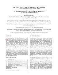
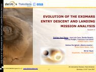
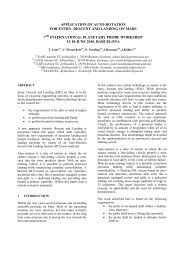
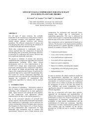
RECOVERY OF IN-SPACE CUBESAT EXPERIMENTS (RICE) PROJECT<br />
Bryan Chan (1) , Nicole Bauer (1) , Jessica R. Juneau (1) , Stephanie Stout (1) , Kento Masuyama (1) , Dave Spencer (1)<br />
(1) Georgia Tech SSDL, 270 Ferst Dr., Atlanta, GA 30332, USA, bchan@gatech.edu, nbauer3@gatech.edu,<br />
jjuneau3@gatech.edu, sstout3@gatech.edu, kmasuyama@gatech.edu, david.spencer@aerospace.gatech.edu:<br />
ABSTRACT<br />
The RICE project is a university project in conjunction<br />
with Eloret Corporation and NASA Ames Research<br />
Center that seeks to develop a low-cost, low-mass<br />
flight system that is capable of exposing scientific<br />
CubeSat experiments to the Low-Earth Orbit (LEO)<br />
environment and safely recovering them for laboratory<br />
analysis on the ground. A CubeSat sized payload was<br />
selected because it is a standard interface system that<br />
has become widely popular with university programs<br />
and the aerospace industry. The proceeding paper will<br />
describe the research and trade studies that have been<br />
completed in order to define mission architecture<br />
possibilities and science payload requirements for the<br />
RICE mission.<br />
1. MISSION ARCHITECTURE DESIGN<br />
The intent of this section is to describe the current<br />
mission architecture for the Recovery of In-Space<br />
CubeSat Experiments (RICE) mission. The mission<br />
objectives and overview are first described, with a<br />
basic explanation of the mission concept and flight<br />
system configuration. Next, the baseline architecture is<br />
outlined within the Grand Menu along with all<br />
architecture possibilities. The overarching baseline<br />
architecture selections are then explained,<br />
incorporating the trade studies and discussions that<br />
went into those decisions. The goal is to present an upto-date<br />
description of the mission architecture for the<br />
RICE mission.<br />
1.1 Mission Concept Overview<br />
The RICE project seeks to develop a low-cost, lowmass<br />
spacecraft that is capable of exposing scientific<br />
CubeSat experiments to the LEO space environment<br />
and safely recovering them for laboratory analysis on<br />
the ground. A CubeSat sized payload was selected<br />
because it is a standard interface system that has<br />
become widely popular with university programs and<br />
the aerospace industry. The overall mission objectives<br />
of RICE are as follows:<br />
1) The RICE mission and flight system will be<br />
designed in order to guarantee payload<br />
recovery and survivability<br />
2) The RICE system shall expose the science<br />
payload to the microgravity environment of<br />
LEO<br />
3) The RICE system shall re-enter the Earth’s<br />
atmosphere and return the science payload to<br />
Earth<br />
4) The RICE mission design will enable rapid<br />
payload recovery after re-entry and landing<br />
5) The RICE system design shall favor<br />
simplicity.<br />
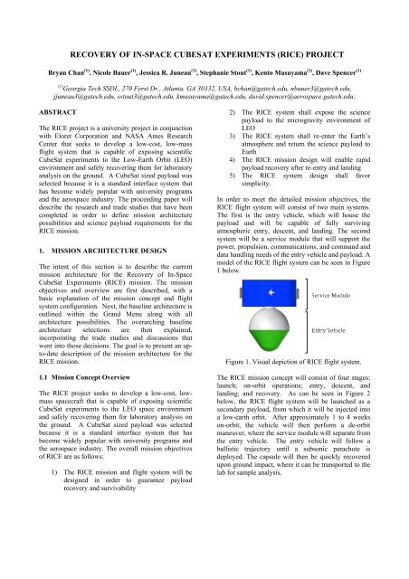
In order to meet the detailed mission objectives, the<br />
RICE flight system will consist of two main systems.<br />
The first is the entry vehicle, which will house the<br />
payload and will be capable of fully surviving<br />
atmospheric entry, descent, and landing. The second<br />
system will be a service module that will support the<br />
power, propulsion, communications, and command and<br />
data handling needs of the entry vehicle and payload. A<br />
model of the RICE flight system can be seen in Figure<br />
1 below.<br />
Figure 1. Visual depiction of RICE flight system.<br />
The RICE mission concept will consist of four stages:<br />
launch; on-orbit operations; entry, descent, and<br />
landing; and recovery. As can be seen in Figure 2<br />
below, the RICE flight system will be launched as a<br />
secondary payload, from which it will be injected into<br />
a low-earth orbit. After approximately 1 to 4 weeks<br />
on-orbit, the vehicle will then perform a de-orbit<br />
maneuver, where the service module will separate from<br />
the entry vehicle. The entry vehicle will follow a<br />
ballistic trajectory until a subsonic parachute is<br />
deployed. The capsule will then be quickly recovered<br />
upon ground impact, where it can be transported to the<br />
lab for sample analysis.
1.3 Description of Baseline Launch Decisions<br />
1.2 Grand Menu<br />
In order to examine all possible design paths for the<br />
RICE mission, a Grad Menu was developed and is<br />
shown in Table 1 in the Appendix. The mission was<br />
divided into four sections: Launch, On-Orbit, Re-<br />
Entry, and Recovery.<br />
The launch section covers all driving design<br />
considerations related to the launch, including the<br />
launch vehicle selection, payload class, launch adapter,<br />
and the launch priority. The on-orbit section largely<br />
covers the service module and payload design. Within<br />
the service module design, considerations exist for<br />
each subsystem, while the payload design focuses on<br />
payload requirements that affect the RICE interface<br />
with the CubeSat. The on-orbit section also includes<br />
the orbit for the RICE mission, including the range of<br />
altitudes and eccentricities considered in the mission<br />
design. The re-entry section focuses on all design<br />
considerations associated with the entry, descent, and<br />
landing portion of the mission. This encompasses the<br />
deceleration method (parachute vs. impact sphere), the<br />
aeroshell geometry, landing footprint, TPS, and<br />
stabilization method for the hypersonic portion of reentry.<br />
Finally, the recovery section covers the entry<br />
vehicle landing and recovery portion of the mission<br />
and all design considerations that affect it. This<br />
includes the baselined landing site, the recovery time<br />
set by the payload requirements, the recovery method,<br />
and the tracking method.<br />
Within the Grand Menu, certain design considerations<br />
have already been eliminated (shown in red) or<br />
baselined (shown in green). Design option elimination<br />
and baseline selections will be explained in the<br />
following section for the design decisions that have the<br />
largest effect on the overall mission and flight system<br />
architecture.<br />
The primary driver of the launch vehicle decisions is<br />
the spacecraft mass and the total mission cost, because<br />
one of the mission objectives of RICE is to keep the<br />
mission as simple as possible. Therefore, the RICE<br />
launch priority was selected to be secondary, because<br />
of the large reduction in mission cost. As a baseline,<br />
the payload class was selected to be the NanoSat, 30 kg<br />
class, because the estimated flight system mass was<br />
within this range. The NanoSat class requires the RSA<br />
launch interface, so it too was chosen as part of the<br />
baseline design. The FalconSat class was eliminated<br />
because the maximum launch payload mass was lower<br />
than the RICE estimated mass.<br />
This largely affects the mass and volume constraints<br />
placed on the flight system. As a NanoSat class<br />
payload, the maximum mass must not exceed 30kg and<br />
the volume must not exceed a cylinder with a diameter<br />
and height of 18.7 inches. The Ride-Share Adapter<br />
(RSA) also requires that the spacecraft be interfaced<br />
using a Lightband attachment and that the payload not<br />
interfere with the survival of the primary payload.<br />
Figure 3 shows the RSA adapter in which the RICE<br />
flight system would occupy the central, octagonal<br />
volume.<br />
Figure 3. RSA with payload envelope [1]<br />
1.4 Description of Baseline Orbit Decisions<br />
For the baseline mission orbit, the simplest case was<br />
selected: low-earth, circular orbit. The range of<br />
altitudes examined was determined by a study of the<br />
de-orbit burn and its effect on the amount of propellant<br />
required, the landing footprint, and the re-entry heat<br />
load. From a study of the de-orbit delta V and the<br />
required propellant (shown in Figure 4), the propellant<br />
mass for the range of -3 to -4 degrees was found to be<br />
relatively constant for orbits between 300km and<br />
1000km. Therefore, that range of altitudes was chosen<br />
as the baseline to be examined in all future analyses.
equirements can be maintained with respect to the<br />
Earth. For now, three omni-directional antennas were<br />
selected, with one placed on the lower surface of the<br />
service module and two placed 180 degrees apart on<br />
the curved service module walls.<br />
Figure 5 below captures the main architecture<br />
decisions that drive the baseline service module design.<br />
Figure 4. Deorbit characteristics for varying altitudes<br />
1.5 Service Module Architecture<br />
For the spacecraft attitude, spin-stabilization was<br />
selected as a baseline. By spin stabilizing about the<br />
minimum moment of inertia axis, the spacecraft would<br />
be more resilient to disturbance torques. The satellite<br />
could also be continually pointed along the solar<br />
vector, allowing for body-mounted solar panels along<br />
the top surface of the service module and maintaining<br />
the entry vehicle within the shadow of the service<br />
module at all times, thus minimizing excessive heating<br />
from the sun. Finally, spin stabilization minimizes the<br />
number of attitude control components required, thus<br />
greatly lowering the overall mass and cost.<br />
For the spacecraft propulsion system, a series of six<br />
micro-thrusters, two per axis, were selected as a<br />
baseline. Two clusters of the thrusters will be placed<br />
on opposite sides of the service module curved walls<br />
and aligned as closely as possible with the vehicle’s<br />
center of mass. This configuration was selected in<br />
order to minimize the amount of internal tubing and to<br />
simplify the attitude control and de-orbit propulsion<br />
system. However, losses exist with the system because<br />
of the offset from the spacecraft’s vertical axis during<br />
the re-entry burn. Further analysis will be done in order<br />
to justify this design choice.<br />
Body-mounted solar panels were baselined for RICE’s<br />
electrical power system for various reasons. First,<br />
using body-mounted rather than deployable solar cells<br />
reduces the risk, complexity, and overall cost of the<br />
system. In addition, because the spacecraft is spinstabilized,<br />
the panels can be placed largely on the top<br />
of the service module and oriented to along the solar<br />
vector at all times.<br />
Finally, for the communications subsystem, omnidirectional<br />
capabilities were selected for the baseline<br />
architecture. Because the spacecraft will be spinstabilized,<br />
it will maintain a fixed position in the<br />
inertial frame, and therefore no strict pointing<br />
Figure 5. Service module architecture for RICE.<br />
1.6 Re-entry Deceleration Method<br />
In order to safely recover the science payload, two<br />
methods of re-entry deceleration were examined. The<br />
first involved an impact sphere, made of carbon foam<br />
that would aid in absorbing the accelerations<br />
experienced during ground impact. The second option<br />
involved using a subsonic parachute. The chute was<br />
selected to be subsonic, because previous POST<br />
analysis showed that the entry vehicle would reach<br />
subsonic speeds during the entry trajectory with<br />
reasonable time to deploy a chute. The driving factor<br />
in the elimination of the impact sphere option was due<br />
to the high accelerations experienced in landing, which<br />
would not be acceptable for most science payloads.<br />
The impact loadings were approximated using Meyer’s<br />
theory, from which maximum accelerations can be<br />
calculated as a function of impact velocity, maximum<br />
capsule diameter, and mass. The expected acceleration<br />
experienced by the science payload upon landing was<br />
estimated to be between 161 and 281 G’s.<br />
In contrast, using a 1kg flare parachute with a drag area<br />
of 7.5 m 2 , the maximum acceleration expected upon<br />
ground impact was calculated to be around 8.43 G’s.<br />
Further analysis will be done in order to predict the<br />
deployment shock, which will depend upon the chute<br />
reefing, packaging, and deployment dynamic pressure.<br />
Certain problems exist with the selection of a parachute<br />
as the deceleration mechanism, including the question<br />
of how the chute will be deployed without<br />
overcomplicating the entry vehicle design. Also, when<br />
a flare parachute was investigated, the oblong<br />
parachute canister forced the entry capsule to be<br />
oversized, which added unnecessary mass and volume.
As a result, alternative parachute housings are being<br />
investigated.<br />
1.7 Aeroshell Geometry<br />
In order to select the proper geometry for the entry<br />
vehicle, or aeroshell, a quantitative survey of four<br />
possible geometries was completed. Several factors<br />
were taken into account, including the vehicle drag<br />
coefficient, the expected heating range, the initial<br />
orientation requirements, the stability in all flight Mach<br />
regimes, the terminal descent architecture, overall<br />
complexity, and finally the flight heritage. After all<br />
considerations, the Mars Microprobe 45 degree<br />
spherecone geometry was selected because of its<br />
excellent stability, its flight heritage, and its overall<br />
complexity. However, because the Microprobe<br />
geometry has a larger volume distribution in its<br />
spherical portion, difficulties will arise when trying to<br />
move the center of gravity forward. This will be<br />
accounted for in the entry vehicle packaging. Table 2<br />
in the appendix shows the factors considered for the<br />
four geometries considered (Mars Microprobe, Sphere,<br />
CEV, and Stardust). Figure 6 below shows a packaging<br />
model of the current entry vehicle design. The<br />
parachute is modeled within a canister, which will<br />
change when a suitable alternative is found. The<br />
insulating shell exists in order to insulate the science<br />
payload from the heat dissipated from the Thermal<br />
Protection System (TPS).<br />
flight path angle. Based on these results SIRCA is the<br />
best candidate material for the heatshield and LI-2200<br />
is the best material for the backshell based on both<br />
mass and volume.<br />
Table 3. Initial TPS sizing results.<br />
Un-‐margined <br />
Thickness (in) <br />
PICA SIRCA LI2200 <br />
Stagnation 0.664 0.315 x <br />
Frustum 0.548 0.254 x <br />
Back shell 0.310 0.134 0.114 <br />
Assumptions <br />
Nose Radius 0.1 m <br />
Velocity 7.6 km/s <br />
FPA -‐3 deg <br />
<strong>Probe</strong> Mass 6.88 kg <br />
Initial Temp 70 F <br />
Base Radius 0.267 m <br />
Cone Angle 45 deg <br />
Reference Info <br />
Peak Heating <br />
(stag) 191 W/cm^2 <br />
Peak Pressure <br />
(stag) 6.26 kPa <br />
Heat Load (stag) 9650 J/cm^2 <br />
2. SCIENCE REQUIREMENTS<br />
Figure 6. Current packaging model of entry vehicle<br />
1.8 TPS Selection<br />
A preliminary trade study of TPS material selection has<br />
been performed using the initial mass and geometry<br />
estimates for the parachute reference configuration and<br />
the -3 to -4 flight path angle. The TRAJ trajectory tool<br />
was used to define the ballistic trajectories, which were<br />
then fed into the FIAT thermal response model. Two<br />
TPS materials were considered for the heat shield<br />
including PICA and SIRCA. Three materials were<br />
considered for the backshell including PICA, SIRCA<br />
and LI-2200 (shuttle tile). Table 3 summarizes the<br />
results and assumptions of the case using a -3 deg<br />
The motivation behind the RICE mission is to build a<br />
framework for cost-effective, recoverable space<br />
missions. While many fields, including materials<br />
science, stand to benefit from the availability of such a<br />
system, the focus is currently on space biology<br />
missions. Results of such experiments will lead to<br />
enhanced understanding of the effects of microgravity<br />
or radiation on biological systems. RICE is not<br />
designed to a single specific mission, but rather is<br />
meant to be compatible with many missions within an<br />
acceptable range of complexity and requirements. The<br />
goal of this section is to define a set of requirements<br />
that the payload will constrain the spacecraft system to<br />
in order to support some envelope of possible missions.
2.1 Science Motivation<br />
There are several fields of science that could benefit<br />
from an inexpensive, flexible platform designed to<br />
expose experiments to aspects of the space<br />
environment and then safely return the experiment to<br />
Earth. One of the most important areas of research that<br />
could benefit from RICE is radiation and microgravity<br />
exposure for biological systems. Understanding of the<br />
effects of both long term exposure to radiation and<br />
microgravity is crucial to the further human<br />
exploration of the solar system and the RICE platform<br />
is a unique capability that would fill gaps in the current<br />
suite of space biology research laboratories.<br />
Existing biological research platforms that have sample<br />
return capability include the Russian Foton/Bion series<br />
spacecraft and the <strong>International</strong> Space Station. Both of<br />
these laboratories come with considerable constraints<br />
including: (a) relatively high mission costs that prevent<br />
a access to space from a large community of<br />
researchers, (b) large gaps in mission opportunities and<br />
long lead times for missions typically result in outdated<br />
science objectives that may be years out of sync with<br />
current research priorities, (c) for the case of the ISS,<br />
human safety constraints limit the environmental<br />
exposure and the place a multitude of requirements on<br />
even the simplest of science experiments. The RICE<br />
platform is specifically designed to reduce the cost of<br />
performing biological research, increase the number of<br />
mission opportunities, and enable access to space<br />
environments that are otherwise unreachable to other<br />
platforms such as high altitude and high inclination<br />
orbits which have a more harsh radiation environment<br />
[2].<br />
In 2007, the Ames Research Center hosted a workshop<br />
to develop concepts for small astrobiology science<br />
missions. The results of the workshop produced<br />
several mission concepts, two of which were small<br />
payload sample return missions [3]. This finding<br />
supports the need for the RICE platform.<br />
2.2 Microgravity and Radiobiology<br />
The combination of long-term exposure to<br />
microgravity and radiation environments cannot be<br />
simulated anywhere on the surface of the Earth. Space<br />
based biological experiments have indicated that the<br />
combination of radiation and microgravity create a<br />
synergy that has the potential to be more destructive<br />
and disable natural repair mechanisms in biological<br />
systems [2]. In addition the type of radiation<br />
encountered in space is unique and difficult to<br />
duplicate in the laboratory. It is well known that<br />
different types of radiation cause different types of<br />
damage to biological systems [4] which is one reason<br />
space based research laboratories are necessary for<br />
radiation research.<br />
2.3 Science Advisory Board<br />
Although RICE is intended to be compatible with a<br />
range of science missions, a set of maximum desirable<br />
capabilities was needed to serve as enveloping<br />
requirements. In order to set these values, a panel of<br />
scientists was put together to brainstorm reference<br />
missions specific to RICE. A charter was put together<br />
explaining the motivation and then-current design of<br />
RICE and distributed to several scientists at Ames,<br />
Georgia Tech, and other universities. Through a series<br />
of telephone conferences, meetings, and surveys,<br />
several possible payloads and associated missions were<br />
identified. These missions fell under several topics,<br />
including biology, materials science, and atmospheric<br />
sciences. However, in order to remain within the<br />
original RICE motivation, the focus has been kept on<br />
biology-related missions.<br />
Several constraints were given to the science panel as<br />
determined by the then-current design of the RICE<br />
spacecraft. These included a 1-U volume and mass<br />
constraint for the science payload, an orbit in Low-<br />
Earth Orbit (LEO), and survivability of the biology<br />
payload during expected waits for integration with the<br />
system as well as with the launch vehicle. Several<br />
common themes arose in response to these restrictions.<br />
One was that many science teams want 2-U allocated<br />
to the payload. Another comment was that<br />
Geosynchronous Transfer Orbit (GTO) offered a more<br />
interesting radiation environment. These are interesting<br />
possibilities whose feasibility will be studied in<br />
possible future generations of RICE. However, for this<br />
first iteration, as explained in the Grand Menu section,<br />
simplicity was a major driver. Table 4 (in the<br />
appendix) shows three reference missions identified<br />
with input from the science panel, which are believed<br />
to be feasible within the current design of the RICE<br />
system and will serve as the starting point for putting<br />
together the RICE science payload requirements.<br />
Other biological payloads and science concepts<br />
discussed include: fruit flys, fish, plants, rodents,<br />
material science, astrobiology, and atmospheric<br />
science.<br />
3. REFERENCES<br />
1. Design Net Engineering, LLC. (n.d.). Falcon<br />
Rideshare Adapter. Retrieved 2010 15-April from<br />
Design Net Engineering: http://www.designgroup.com/content/RideShareAdapterFC.pdf
2. Nelson, G. A. (1994). Radiation In Microgravity.<br />
Pasadena, CA: Jet Propulsion Laboratories.<br />
3. Yost, B., Fishman, J. L., & Fonda, M. (2007).<br />
Astrobiology Small Payloads <strong>Workshop</strong> Report.<br />
Moffett Field, CA: NASA Ames Research Center.<br />
4. Nelson, G. A. (2003). Fundamental Space<br />
Radiobiology. Gravitational and Space Biology<br />
Bulletin .
Table 1. RICE Grand Menu
Table 2. Summary of aeroshell geometry study.<br />
Table 4. Reference requirements for RICE biological payload.<br />
Field of Science Space Biology Space Biology Space Biology<br />
Microorganisms Snails in<br />
Human Tissue in<br />
Reference<br />
in Microgravity/ Microgravity/ Microgravity/<br />
Mission<br />
Radiation Radiation<br />
Radiation<br />
Science<br />
Objective<br />
Science<br />
Objective<br />
Science Priority<br />
Data Sources<br />
Determine the<br />
effects of<br />
microgravity on<br />
live animal<br />
development.<br />
Informs<br />
decisions on the<br />
design of<br />
exploration<br />
mission systems.<br />
See ASGSB<br />
(http://asgsb.org/i<br />
ndex.php) for<br />
links to relevant<br />
pubs.<br />
Determine the<br />
effects of<br />
microgravity on live<br />
animal<br />
development.<br />
Informs decisions<br />
on the design of<br />
exploration mission<br />
systems.<br />
See ASGSB<br />
(http://asgsb.org/in<br />
dex.php) for links to<br />
relevant pubs.<br />
Determine the<br />
effects of<br />
microgravity on live<br />
animal<br />
development.<br />
Informs decisions<br />
on the design of<br />
exploration mission<br />
systems.<br />
See ASGSB<br />
(http://asgsb.org/in<br />
dex.php) for links to<br />
relevant pubs.
Requirement<br />
Area<br />
Volume<br />
Mass<br />
Thermal<br />
Management<br />
Environmental<br />
Exposure<br />
On-Orbit Mission<br />
Life<br />
Max Recovery<br />
Time<br />
Minimum: 1 U<br />
CubeSat volume;<br />
2U greatly<br />
increases<br />
capability<br />
Minimum: 1 kg, 3-<br />
4 kg greatly<br />
increases<br />
capability<br />
20-25 C thermal<br />
control provided<br />
to CubeSat<br />
surface<br />
Microgravity,<br />
high inclination<br />
orbits will have<br />
high radiation<br />
exposure<br />
20-60 days or<br />
more is desirable<br />
to increase<br />
radiation<br />
exposure<br />
Minimum: 2U<br />
Minimum: 3-4 kg<br />
10-40 C thermal<br />
control provided to<br />
CubeSat surface<br />
Microgravity, high<br />
inclination orbits<br />
will have high<br />
radiation exposure<br />
20-60 days or more<br />
is desirable to<br />
increase radiation<br />
exposure [est.]<br />
6 hours 6 hours 6 hours<br />
Minimum: 1 U<br />
CubeSat volume;<br />
2U greatly<br />
increases capability<br />
Minimum: 1 kg, 3-4<br />
kg greatly<br />
increases capability<br />
20-25 C thermal<br />
control provided to<br />
CubeSat surface<br />
(must have 37 +/-<br />
0.1 deg C at<br />
sample)<br />
Microgravity, high<br />
inclination orbits<br />
will have high<br />
radiation exposure<br />
20-60 days or more<br />
is desirable to<br />
increase radiation<br />
exposure<br />
Static Inertial<br />
Loading<br />
At least Bion<br />
flight profile<br />
At least Bion flight<br />
profile<br />
At least Bion flight<br />
profile<br />
Dynamic Inertial<br />
Loading<br />
Total Electrical<br />
Energy<br />
Data Storage<br />
Communications<br />
Launch<br />
Integration Time<br />
500 MB of<br />
monitoring<br />
environmental<br />
data<br />
Real time<br />
temperature<br />
monitoring<br />
(updates at least<br />
every 6 hrs)<br />
500 MB of<br />
monitoring<br />
environmental data<br />
Real time<br />
temperature<br />
monitoring<br />
(updates at least<br />
every 6 hrs)<br />
500 MB of<br />
monitoring<br />
environmental data<br />
Real time<br />
temperature<br />
monitoring<br />
(updates at least<br />
every 6 hrs)<br />
3 weeks 3 weeks 3 weeks