eagle - International Planetary Probe Workshop
eagle - International Planetary Probe Workshop
eagle - International Planetary Probe Workshop

You also want an ePaper? Increase the reach of your titles
YUMPU automatically turns print PDFs into web optimized ePapers that Google loves.
EAGLE: AN EXTENSIBLE, END-TO-END SIMULATION AND EVALUATION<br />
FRAMEWORK FOR PLANETARY EDLS<br />
Ender St. John-Olcayto (1) , Guy Johns (2) , Alastair Pidgeon (3) , Christian Philippe (4)<br />
(1) SciSys U.K. Ltd, Methuen Park, Chippenham, Wiltshire SN14 0GB, U.K., Email: Ender.Olcayto@scisys.co.uk<br />
(2) SciSys U.K. Ltd., 23 Clothier Road, Bristol, Avon BS4 5SS, U.K., Email: Guy.Johns@scisys.co.uk<br />
(3) SciSys U.K. Ltd, Methuen Park, Chippenham, Wiltshire SN14 0GB, U.K., Email: Alastair.Pidgeon@scisys.co.uk<br />
(4) ESTEC, Keplerlaan 1, Postbus 299, 2200 AG Noordwijk, The Netherlands, Email: christian.philippe@esa.int<br />
ABSTRACT<br />
This paper introduces the EAGLE model-based design<br />
simulator framework for designing and testing<br />
guidance navigation algorithms for planetary probe<br />
entry / descent, landing and terminal-phase algorithms.<br />
EAGLE has been developed to aid systems engineers<br />
involved in the design, maturation, and evaluation of<br />
these algorithms throughout the design phases of the<br />
space system engineering life-cycle.<br />
This paper will describe the design goals and the<br />
principal elements of the software. The work-flow for<br />
maturing the technology readiness level of the<br />
algorithms will also be discussed.<br />
1. INTRODUCTION<br />
Entry, descent, and landing (E/DL 1 ) is one of the most<br />
critical parts of a surface planetary mission following<br />
the launch sequence. It is also a mission phase that is<br />
most reliant on spacecraft autonomy with little scope<br />
for human intervention. For this reason, E/DL is<br />
subject to high levels of simulation-based evaluation<br />
during each of the design phases of the space system<br />
engineering lifecycle (SSEL) [1].<br />
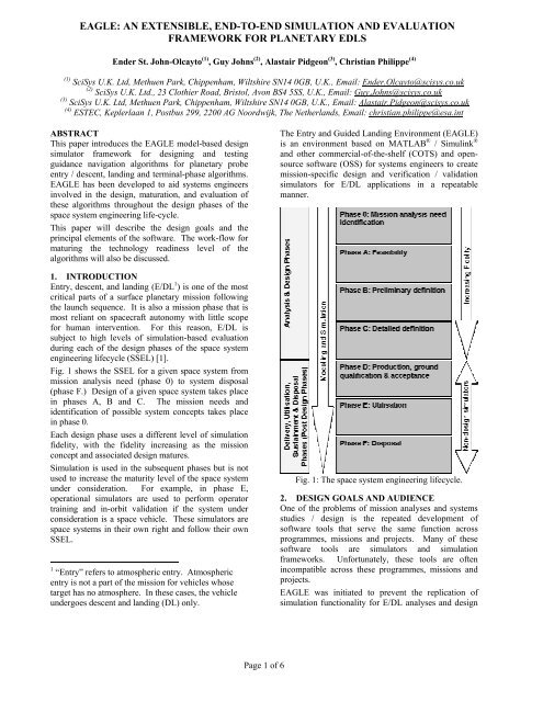
Fig. 1 shows the SSEL for a given space system from<br />
mission analysis need (phase 0) to system disposal<br />
(phase F.) Design of a given space system takes place<br />
in phases A, B and C. The mission needs and<br />
identification of possible system concepts takes place<br />
in phase 0.<br />
Each design phase uses a different level of simulation<br />
fidelity, with the fidelity increasing as the mission<br />
concept and associated design matures.<br />
Simulation is used in the subsequent phases but is not<br />
used to increase the maturity level of the space system<br />
under consideration. For example, in phase E,<br />
operational simulators are used to perform operator<br />
training and in-orbit validation if the system under<br />
consideration is a space vehicle. These simulators are<br />
space systems in their own right and follow their own<br />
SSEL.<br />
1 “Entry” refers to atmospheric entry. Atmospheric<br />
entry is not a part of the mission for vehicles whose<br />
target has no atmosphere. In these cases, the vehicle<br />
undergoes descent and landing (DL) only.<br />
The Entry and Guided Landing Environment (EAGLE)<br />
is an environment based on MATLAB ® / Simulink ®<br />
and other commercial-of-the-shelf (COTS) and opensource<br />
software (OSS) for systems engineers to create<br />
mission-specific design and verification / validation<br />
simulators for E/DL applications in a repeatable<br />
manner.<br />
Fig. 1: The space system engineering lifecycle.<br />
2. DESIGN GOALS AND AUDIENCE<br />
One of the problems of mission analyses and systems<br />
studies / design is the repeated development of<br />
software tools that serve the same function across<br />
programmes, missions and projects. Many of these<br />
software tools are simulators and simulation<br />
frameworks. Unfortunately, these tools are often<br />
incompatible across these programmes, missions and<br />
projects.<br />
EAGLE was initiated to prevent the replication of<br />
simulation functionality for E/DL analyses and design<br />
Page 1 of 6
phases (in its present form, it is capable of supporting<br />
parts of phase D and E.)<br />
The initial design goal of EAGLE is to provide a<br />
platform for the design and evaluation of GNC<br />
algorithms for Mars EDL (such as the ESA Mars EDL<br />
Demonstrator) and Lunar DL (such as the ESA Lunar<br />
Lander) vehicles. However, it can be applied to other<br />
applications such as Earth, Venus and Titan EDL.<br />
Additionally, it can be applied to non-ED/L spacecraft<br />
applications such as aerobraking and asteroid<br />
rendezvous / landing.<br />
Although primarily aimed at the SSEL design phases<br />
for GNC, EAGLE can also be used to create simulators<br />
(and simulation components) for evaluating candidate<br />
mission concepts during phase 0 and phase D (where<br />
specialized simulators are required for hardware /<br />
software integration and test.)<br />
EAGLE provides a framework for creating coupled<br />
multi-body vehicle and vehicle / environmental<br />
simulators using a model-based design (MBD)<br />
philosophy. This approach requires mathematical<br />
models (either first-principles models, data-centric<br />
models such as look-up tables and polynomial<br />
approximations, or combinations of the two) to be<br />
integrated so that a single mathematical model is<br />
obtained. The MBD philosophy then requires this<br />
model to be simulated with the results being used to<br />
drive mission and design decisions.<br />
The target users include:<br />
1. Mission Systems Engineers:<br />
Mission Systems Engineers perform feasibility<br />
studies and design the mission concepts and<br />
architectures. Additionally, mission systems<br />
engineers select the mission system candidate(s)<br />
that is (are) most likely to satisfy the science, cost,<br />
and schedule constraints imposed by the<br />
programme.<br />
2. Systems Engineers:<br />
Systems engineers perform integrated system<br />
design and system trade-offs to obtain solutions<br />
that are optimal with respect to the mission goals<br />
and constraints. They flow down mission and<br />
system requirements to subject matter experts<br />
(SMEs) such as GNC engineers.<br />
3. GNC Engineers:<br />
GNC Engineers develop guidance, navigation and<br />
control (GNC) algorithms, hazard detection and<br />
avoidance (HAD) algorithms. Additionally, GNC<br />
engineers specify / select GNC related hardware<br />
(such as sensing and actuation subsystems) and<br />
place requirements on the on-board computing<br />
resources.<br />
4. Other Subject Matter Experts:<br />
SMEs such as specialists in decelerator<br />
technologies, propulsion systems, power systems<br />
and other hardware engineers can provide<br />
subsystem and component models and integrate<br />
them into EAGLE.<br />
3. EAGLE CAPABILITIES<br />
The EAGLE framework is used to create simulators of<br />
appropriate fidelity for the design, testing and<br />
maturation of GNC and related algorithms. It supports<br />
the V-model [2] of system engineering as shown in<br />
Fig. 2.<br />
Fig. 2: EAGLE supports the V-model of system<br />
engineering.<br />
The V-model is supported through automated testing at<br />
every stage of the system design process (test suites are<br />
executed corresponding to the different design stages<br />
on left hand side of the diagram.) Additionally, the<br />
flight software verification and validation activities are<br />
supported by the following (sequential) simulation<br />
modes:<br />
1. Model-in-the-loop (MIL): Native Simulink blocks<br />
are used to represent the environment, the vehicle<br />
and the GNC algorithms / other flight software.<br />
2. Software-in-the-loop (SIL): The blocks<br />
representing the flight software are converted to<br />
code for the host platform (upon which EAGLE<br />
executes) using TargetLink ® . This code is<br />
compiled and linked with Simulink and replaces<br />
the corresponding native Simulink blocks.<br />
3. Processor-in-the-loop (PIL): The blocks<br />
representing the flight software are converted to<br />
code for the target platform (a flight-representative<br />
processor.) The vehicle and environment models<br />
are converted to code using TargetLink and<br />
compiled on a dSpace ® real-time, hardware<br />
system. A network then connects the processor<br />
and the real-time vehicle / environment model to<br />
enable feedback control.<br />
4. Hardware-in-the-loop (HIL): This is the same as<br />
the above but with flight hardware (such as<br />
sensors) replacing elements of the vehicle model.<br />
Page 2 of 6
An important part of flight software is its ability to<br />
respond to the effects of various in-flight contingencies<br />
(such as the occurrence of a failure mode or an<br />
unexpected environmental condition.) For this reason,<br />
EAGLE provides the user with the ability to trigger<br />
faults in the vehicle model’s subsystems and to change<br />
parameters that represent environmental variables.<br />
These faults and parameter changes can also be<br />
triggered from MATLAB scripts permitting automated<br />
testing of robustness and fault detection and recovery<br />
(FDIR) algorithms.<br />
EAGLE is also able to support phase D and phase E of<br />
a spacecraft’s lifecycle by permitting the generation of<br />
ESA’s simulation portability (SMP) standard<br />
compliant code (for SMP1 and SMP2) through the<br />
Mosaic [3] target for Real-Time <strong>Workshop</strong> ® . The<br />
automatically generated code can be compiled and<br />
linked into other frameworks such as real-time<br />
operational simulators for training, in-orbit validation,<br />
and vehicle anomaly-handling activities.<br />
4. ARCHITECTURE AND DESIGN<br />
EAGLE consists of the following elements (see Fig. 3):<br />
1. The simulation kernel,<br />
2. Analysis tools,<br />
3. Design tools,<br />
4. Graphical User Interface.<br />
Fig. 3: The primary components of EAGLE and the<br />
data flows between them.<br />
The simulation kernel supports continuous-time and<br />
discrete-time models for vehicle / environmental and<br />
algorithm state propagation respectively. Additionally,<br />
EAGLE also supports both variable-step and fixed-step<br />
propagation of the continuous-time states; the former<br />
used for desktop simulation and the latter used for PIL<br />
and HIL simulation.<br />
Simulation kernel: The simulation kernel is<br />
implemented in MATLAB and Simulink. It is<br />
comprised of Simulink blocks and supporting<br />
MATLAB files. The blocks are integrated into the<br />
Simulink user-interface as a “blockset” (Fig. 4.) This<br />
enables rapid building of models by users who are<br />
already well-versed in this popular simulation package.<br />
Fig. 4: The EAGLE blockset.<br />
The blockset is arranged into six sub-libraries:<br />
1. Dynamics: 3 / 6 DOF (Euler angle and quaternion<br />
computation), ablating rigid body, mass properties<br />
evolution, tank dynamics, fuel slosh, flexible<br />
structures, parachutes and airbags.<br />
2. Environment: Atmospheric (simple model, Earth<br />
models: NRL-MSISE00, GRAM2007, Mars<br />
models: EMCD, MarsGRAM2005), ground<br />
interactions and gravity (Nth order harmonics.)<br />
3. Mathematics: Coordinate transformations, vector<br />
and quaternion mathematics, aerodynamic angles.<br />
4. Actuators: On / off thrusters (suitable for pulsewidth<br />
modulation control and timed control) and<br />
continuously variable thrusters.<br />
5. Logic / Control: Flight regime modes (ballistic<br />
entry, parachute deceleration, powered descent,<br />
landing) and GNC / HDA models.<br />
6. Sensors: Landing LIDAR (provided through<br />
PANGU 2 [4]), accelerometers / gyros, camera,<br />
pressure measurement, Doppler radar (provided<br />
through PANGU), star tracker.<br />
2 PANGU: Planet and Asteroid Natural Scene<br />
Generation Utility software created by the Space<br />
Systems Research Group, the University of Dundee.<br />
Page 3 of 6
Comprehensive documentation for each block is<br />
provided through the Simulink on-line help facility.<br />
New blocks can be integrated into the appropriate sublibrary<br />
provided that they adhere to the EAGLE block<br />
interface standard. Blocks undergo a strict<br />
qualification procedure by which simulated data is<br />
compared with actual data (for example, from the<br />
manufacturer of the hardware being modelled or from<br />
actual space missions.)<br />
Analysis tools: Post-simulation analysis of results can<br />
be made through a number of different tools. These<br />
include statistical (such as landing dispersion as shown<br />
in Fig. 5) and dynamic analyses (such as dynamic<br />
pressure as shown in Fig. 6.)<br />
The current revision of EAGLE interfaces with the<br />
Worst-Case Analysis Tool (WCAT) from the<br />
University of Leicester. This tool can reduce the<br />
computational effort in determining the robustness to<br />
parameter variations. Robustness is normally<br />
determined through computationally intensive Monte<br />
Carlo methods.<br />
Graphical User interface: Following the creation of a<br />
simulator using the Simulink interface, all further<br />
interaction with the simulator is achieved through the<br />
EAGLE GUI (see Fig. 7), which is a Java-based<br />
application built using the Eclipse software<br />
development environment. The user has full control<br />
over the parameters used in the simulator. The benefits<br />
of separating the GUI from the simulator are:<br />
1. Non-users of MATLAB and Simulink can execute<br />
simulations and to analyse their results,<br />
2. It ensures that the simulator structure is not<br />
changed accidentally,<br />
3. The functions of the GUI and the simulator /<br />
simulator elements are separated which permits<br />
each to be maintained separately.<br />
Fig. 5: Landing dispersion in Cartesian coordinates.<br />
Fig. 7: The EAGLE graphical user interface.<br />
Fig. 6: Simulated dynamic pressure during entry.<br />
Design tools: Since the EAGLE simulation kernel is<br />
implemented in MATLAB and Simulink, many tools<br />
can be employed for design. The Control System<br />
Toolbox (upon which EAGLE relies to represent<br />
linear systems) can be used to design control loops.<br />
The data objects within EAGLE can also be used with<br />
the Robust Control Toolbox.<br />
5. EAGLE WORK-FLOW<br />
EAGLE provides an iterative simulation workflow (see<br />
Fig. 8) that starts with the simulation needs of phase 0<br />
and phases A studies. These studies provide data<br />
products for the simulation needs of subsequent system<br />
engineering phases; culminating in the validation of<br />
flight software.<br />
To support the above workflow, EAGLE provides four<br />
macro-levels of simulation fidelity that are mapped to<br />
the following simulation classes:<br />
1. System concepts simulator (SCS),<br />
Page 4 of 6
2. Mission performance simulator (MPS),<br />
3. Non-real-time functional engineering simulator<br />
(NRT-FES),<br />
4. Avionics test bed (ATB).<br />
EAGLE provides an iterative simulation workflow (see<br />
Fig. 8) that starts with the simulation needs of phase 0<br />
and phase A studies and provides data products for the<br />
simulation needs of subsequent SSEL phases,<br />
culminating in validated flight software.<br />
To support the above workflow, EAGLE provides four<br />
macro-levels of simulation fidelity that are mapped to<br />
the following simulation classes:<br />
1. System concepts simulator (SCS),<br />
2. Mission performance simulator (MPS),<br />
3. Non-real-time functional engineering simulator<br />
(NRT-FES),<br />
4. Avionics test bed (ATB).<br />
architecture. The MCS permits parameter trade-offs<br />
and robustness tests (through Monte Carlo methods) of<br />
the GNC concept to be performed.<br />
NRT-FES: The NRT-FES represents another<br />
increment in simulation fidelity and is derived from the<br />
MCS. It is used to focus on specific mission phases<br />
and events (such as parachute / airbag / landing leg<br />
deployments) and also to confirm GNC robustness in a<br />
full fidelity simulation. The NRT-FES may be<br />
bypassed, with the MPS being converted to the ATB<br />
directly.<br />
ATB: The ATB is used to evaluate the GNC<br />
algorithms in a real-time environment that represents<br />
the spacecraft computing resources as closely as<br />
possible (LEON 3 processors.) The ATB is especially<br />
useful in determining if the GNC algorithms satisfy<br />
timing, memory, and fault recovery constraints. The<br />
fidelity level of the spacecraft (dynamics, sensors,<br />
actuators, etc.) and the environment is equivalent to<br />
that of the MPS. The spacecraft and environment<br />
models are converted to real-time code and compiled<br />
and linked to run on the dSpace platform. This<br />
processor-in-the-loop architecture as shown in Fig. 9<br />
provides end-to-end simulation capability.<br />
Fig. 8: The EAGLE simulation development workflow.<br />
These simulation fidelity levels are described below:<br />
SCS: The SCS is built in a desktop computing<br />
environment. The purpose of the SCS is to determine<br />
the feasibility of the selected mission from the<br />
vehicle’s final trajectory correction manoeuvre to the<br />
lander touch-down point. A key feature of the SCS is<br />
that it operates much more quickly than wall-clock<br />
time. This is achieved using relatively simple<br />
spacecraft, environment, and algorithmic models (for<br />
example, point mass / single body representations of<br />
the spacecraft and a simple atmospheric model.) This<br />
simulation speed permits mission concepts to be<br />
evaluated, accepted / rejected, or modified quickly.<br />
MPS: Like the SCS, the MPS is built on the desktop.<br />
The MCS is a refinement of the SCS and is used to<br />
elaborate the spacecraft and environmental models.<br />
Aspects of the MCS include full 6 DOF modelling of<br />
all the spacecraft bodies, a realistic atmospheric model,<br />
and fault injection capability. After the necessary<br />
refinements and elaborations have been performed, the<br />
MCS provides a platform for the definition of a GNC<br />
Fig. 9: The architecture of an EAGLE ATB simulator.<br />
6. CONCLUSIONS AND FURTHER WORK<br />
The EAGLE simulation framework has been presented.<br />
The need for such a framework and the intended<br />
audience has been described. The primary capabilities<br />
of EAGLE and its architecture were also presented.<br />
Finally, the workflow for maturing the GNC<br />
algorithms was presented.<br />
EAGLE is being used (and improved) on several other<br />
projects, funded both internal to and external from<br />
SciSys. Recently completed work permits the<br />
modelling of the power generation (battery charging,<br />
solar-electric generation with eclipse effects) and usage<br />
of various subsystems. This permits the system<br />
engineer with another tool for requirements generation<br />
and compliance.<br />
Page 5 of 6
Work is also under way to extend the number of<br />
gravity models available in the EAGLE blockset.<br />
Recently, a panel method for high-fidelity<br />
representation of gravity fields of irregularly shaped<br />
bodies was developed at SciSys and this is being<br />
integrated with EAGLE currently. This method is<br />
useful for asteroid rendezvous and also for modelling<br />
local gravitational effects in the vicinity of vehicle<br />
landing sites.<br />
7. ACKNOWLEDGEMENTS<br />
SciSys is grateful for the support of ESTEC contract<br />
21286/07/NL/EK under which EAGLE is being<br />
developed for ESA. The authors are also grateful for<br />
the help provided by Michelangelo Russo and Benoit<br />
Pigneur of SciSys during the preparation of this paper.<br />
8. REFERENCES<br />
1. Space Engineering / System Engineering General<br />
Requirements, ECSS-E-ST-10 C. European<br />
Cooperation for Space Standardization, 6 March 2007<br />
2. Forsberg, K. and Mooz, H., System Engineering<br />
for Faster, Cheaper, Better. Internal report of the<br />
Center for Systems Management, Inc. Available at<br />
http://bit.ly/dmEcoR.<br />
3. Moelands, J.M., Lammen, W.F., Jansen, M.,<br />
Arcioni, M., Wijnands, Q., Automatic Model Transfer<br />
from MATLAB / Simulink to Simulation Model<br />
Portability 2. The Netherlands National Aerospace<br />
Laboratory internal report NLR-TP-2006-674.<br />
Available at http://bit.ly/cVnMJc.<br />
4. Parkes, S., Dunstan, M., Mendham, P.,<br />
Mancuso, S., Planet Surface Simulation Testing<br />
Vision-based Autonomous <strong>Planetary</strong> Landers.<br />
Page 6 of 6