application of auto-rotation for entry, descent and landing on mars 7 ...
application of auto-rotation for entry, descent and landing on mars 7 ...
application of auto-rotation for entry, descent and landing on mars 7 ...

You also want an ePaper? Increase the reach of your titles
YUMPU automatically turns print PDFs into web optimized ePapers that Google loves.
APPLICATION OF AUTO-ROTATION<br />
FOR ENTRY, DESCENT AND LANDING ON MARS<br />
7 TH INTERNATIONAL PLANETARY PROBE WORKSHOP<br />
12-18 JUNE 2010, BARCELONA<br />
T. Lutz (1) , U. Westerholt (2) , P. Noeding (3) , S.Ransom (4) , J.Köhler (5)<br />
(1) EADS Astrium ST, Airbusallee 1, 28199 Bremen, Germany, tobias.lutz@astrium.eads.net<br />
(2) EADS Astrium ST, Airbusallee 1, 28199 Bremen, Germany, uwe.westerholt@astrium.eads.net<br />
(3) EADS Astrium ST, Airbusallee 1, 28199 Bremen, Germany, peter.noeding@astrium.eads.net<br />
(4) SRC<strong>on</strong>sultancy, Kiebitzstraße 31, 28816 Stuhr, Germany, src<strong>on</strong>sultancy@freenet.de<br />
(5) ESA/ESTEC, Keplerlaan 1, Noordwijk, The Netherl<str<strong>on</strong>g>and</str<strong>on</strong>g>s, Johan.Kohler@esa.int<br />
ABSTRACT<br />
Entry, Descent <str<strong>on</strong>g>and</str<strong>on</strong>g> L<str<strong>on</strong>g>and</str<strong>on</strong>g>ing (EDL) <strong>on</strong> Mars is in the<br />
focus <str<strong>on</strong>g>of</str<strong>on</strong>g> <strong>on</strong>-going engineering activities in support to<br />
future interplanetary missi<strong>on</strong>s. Main technology drivers<br />
in this c<strong>on</strong>text are:<br />
• the requirements to be able to l<str<strong>on</strong>g>and</str<strong>on</strong>g> at higher<br />
altitudes,<br />
• to per<str<strong>on</strong>g>for</str<strong>on</strong>g>m precisi<strong>on</strong> l<str<strong>on</strong>g>and</str<strong>on</strong>g>ing <str<strong>on</strong>g>and</str<strong>on</strong>g> finally<br />
• to per<str<strong>on</strong>g>for</str<strong>on</strong>g>m hazard avoidance maneuvers.<br />
A new approach towards Descent <str<strong>on</strong>g>and</str<strong>on</strong>g> L<str<strong>on</strong>g>and</str<strong>on</strong>g>ing is<br />
presented within this paper which shall especially<br />
fulfill the new requirements <str<strong>on</strong>g>of</str<strong>on</strong>g> precisi<strong>on</strong> l<str<strong>on</strong>g>and</str<strong>on</strong>g>ing <str<strong>on</strong>g>and</str<strong>on</strong>g><br />
hazard avoidance. During an ESA study the idea <str<strong>on</strong>g>of</str<strong>on</strong>g><br />
l<str<strong>on</strong>g>and</str<strong>on</strong>g>ing payloads by means <str<strong>on</strong>g>of</str<strong>on</strong>g> an Auto-Rotati<strong>on</strong><br />
<str<strong>on</strong>g>descent</str<strong>on</strong>g> <str<strong>on</strong>g>and</str<strong>on</strong>g> L<str<strong>on</strong>g>and</str<strong>on</strong>g>ing System (DLS) was analyzed.<br />
Auto-<str<strong>on</strong>g>rotati<strong>on</strong></str<strong>on</strong>g> is a state <str<strong>on</strong>g>of</str<strong>on</strong>g> moti<strong>on</strong> in which the air<br />
stream around a free-falling vehicle propels a rotor<br />
such that the rotor produces thrust. With an <str<strong>on</strong>g>auto</str<strong>on</strong>g>rotating<br />
vehicle it is possible to per<str<strong>on</strong>g>for</str<strong>on</strong>g>m precisi<strong>on</strong><br />
l<str<strong>on</strong>g>and</str<strong>on</strong>g>ing while maintaining complete c<strong>on</strong>trollability. A<br />
Martian DLS based <strong>on</strong> <str<strong>on</strong>g>auto</str<strong>on</strong>g>-<str<strong>on</strong>g>rotati<strong>on</strong></str<strong>on</strong>g> can, there<str<strong>on</strong>g>for</str<strong>on</strong>g>e,<br />
decelerate after <str<strong>on</strong>g>entry</str<strong>on</strong>g> like a parachute equipped system<br />
<str<strong>on</strong>g>and</str<strong>on</strong>g> glide to a dedicated l<str<strong>on</strong>g>and</str<strong>on</strong>g>ing site providing also<br />
hazard avoidance capability. Within this paper such a<br />
system c<strong>on</strong>cept is presented.<br />
1 INTRODUCTION<br />
Within the next years several missi<strong>on</strong>s aim <strong>on</strong> l<str<strong>on</strong>g>and</str<strong>on</strong>g>ing<br />
scientific payloads <strong>on</strong> Mars. Most <str<strong>on</strong>g>of</str<strong>on</strong>g> the upcoming<br />
missi<strong>on</strong>s are rover missi<strong>on</strong>s, but also other scientific<br />
payloads are to be delivered to the surface. In the l<strong>on</strong>g<br />
term some missi<strong>on</strong>s aim at paving the way towards the<br />
first man-rated missi<strong>on</strong>.<br />
In this c<strong>on</strong>text <strong>on</strong>e critical technology to master is the<br />
<str<strong>on</strong>g>entry</str<strong>on</strong>g>, <str<strong>on</strong>g>descent</str<strong>on</strong>g> <str<strong>on</strong>g>and</str<strong>on</strong>g> l<str<strong>on</strong>g>and</str<strong>on</strong>g>ing (EDL). While previous<br />
missi<strong>on</strong>s targeted to reach easy-to-access l<str<strong>on</strong>g>and</str<strong>on</strong>g>ing sites<br />
with minor precisi<strong>on</strong> requirements, the more ambitious<br />
scientific missi<strong>on</strong>s will have to cope with new issues.<br />
Main technology drivers in this c<strong>on</strong>text are the<br />
requirements to be able to l<str<strong>on</strong>g>and</str<strong>on</strong>g> at higher altitudes, to<br />
per<str<strong>on</strong>g>for</str<strong>on</strong>g>m precisi<strong>on</strong> l<str<strong>on</strong>g>and</str<strong>on</strong>g>ing <str<strong>on</strong>g>and</str<strong>on</strong>g> finally to per<str<strong>on</strong>g>for</str<strong>on</strong>g>m<br />
hazard avoidance manoeuvres. The typical approach<br />
<str<strong>on</strong>g>for</str<strong>on</strong>g> such an EDL scenario is to use supers<strong>on</strong>ic<br />
parachutes in combinati<strong>on</strong> with powered s<str<strong>on</strong>g>of</str<strong>on</strong>g>t-l<str<strong>on</strong>g>and</str<strong>on</strong>g>ing.<br />
Clearly, the per<str<strong>on</strong>g>for</str<strong>on</strong>g>mance <str<strong>on</strong>g>of</str<strong>on</strong>g> a powered l<str<strong>on</strong>g>and</str<strong>on</strong>g>er is<br />
restricted by its amount <str<strong>on</strong>g>of</str<strong>on</strong>g> propellant, while all <str<strong>on</strong>g>of</str<strong>on</strong>g> its<br />
initial kinetic energy is dissipated during <str<strong>on</strong>g>entry</str<strong>on</strong>g> <str<strong>on</strong>g>and</str<strong>on</strong>g><br />
parachute <str<strong>on</strong>g>descent</str<strong>on</strong>g>. This disadvantage might be avoided<br />
by the implementati<strong>on</strong> <str<strong>on</strong>g>of</str<strong>on</strong>g> an <str<strong>on</strong>g>auto</str<strong>on</strong>g>rotative <str<strong>on</strong>g>descent</str<strong>on</strong>g> <str<strong>on</strong>g>and</str<strong>on</strong>g><br />
l<str<strong>on</strong>g>and</str<strong>on</strong>g>ing system.<br />
Auto-<str<strong>on</strong>g>rotati<strong>on</strong></str<strong>on</strong>g> is a state <str<strong>on</strong>g>of</str<strong>on</strong>g> moti<strong>on</strong> in which the air<br />
stream around a free-falling vehicle propels a rotor<br />
such that the rotor produces thrust. Helicopters use this<br />
principal to l<str<strong>on</strong>g>and</str<strong>on</strong>g> safely in the event <str<strong>on</strong>g>of</str<strong>on</strong>g> turbine failure.<br />
With an <str<strong>on</strong>g>auto</str<strong>on</strong>g>-rotating vehicle it is possible to per<str<strong>on</strong>g>for</str<strong>on</strong>g>m<br />
precisi<strong>on</strong> l<str<strong>on</strong>g>and</str<strong>on</strong>g>ing while maintaining complete<br />
c<strong>on</strong>trollability. A Martian EDL system based <strong>on</strong> <str<strong>on</strong>g>auto</str<strong>on</strong>g><str<strong>on</strong>g>rotati<strong>on</strong></str<strong>on</strong>g><br />
can, there<str<strong>on</strong>g>for</str<strong>on</strong>g>e, decelerate after <str<strong>on</strong>g>entry</str<strong>on</strong>g> like a<br />
parachute equipped system <str<strong>on</strong>g>and</str<strong>on</strong>g> glide to a dedicated<br />
l<str<strong>on</strong>g>and</str<strong>on</strong>g>ing site reaching down-range capability as high as<br />
25 kilometres. This paper describes such a system<br />
c<strong>on</strong>cept, its applicability <str<strong>on</strong>g>and</str<strong>on</strong>g> the need <str<strong>on</strong>g>for</str<strong>on</strong>g> technology<br />
dem<strong>on</strong>strati<strong>on</strong>.<br />
The work described here is based <strong>on</strong> the following<br />
requirements:<br />
• the probe to be l<str<strong>on</strong>g>and</str<strong>on</strong>g>ed shall follow a ballistic<br />
<str<strong>on</strong>g>entry</str<strong>on</strong>g> trajectory,<br />
• the probe shall have a Viking-like aeroshell,<br />
• the probe shall be l<str<strong>on</strong>g>and</str<strong>on</strong>g>ed at altitudes below<br />
2000 m,
• the probe shall be l<str<strong>on</strong>g>and</str<strong>on</strong>g>ed at a <str<strong>on</strong>g>descent</str<strong>on</strong>g> velocity<br />
<str<strong>on</strong>g>of</str<strong>on</strong>g> less than 20 m/s,<br />
• the l<str<strong>on</strong>g>and</str<strong>on</strong>g>ing vehicle shall be capable <str<strong>on</strong>g>of</str<strong>on</strong>g><br />
manoeuvring close to the surface prior to<br />
touchdown, <str<strong>on</strong>g>and</str<strong>on</strong>g><br />
• the l<str<strong>on</strong>g>and</str<strong>on</strong>g>ed mass shall be between 20 <str<strong>on</strong>g>and</str<strong>on</strong>g><br />
200 kg.<br />
2 MARS ENTRY, DESCENT AND LANDING<br />
CHALLENGES AND SOLUTIONS<br />
For scientific missi<strong>on</strong>s <strong>on</strong> Mars it is necessary to<br />
decelerate a probe from interplanetary arrival speeds <str<strong>on</strong>g>of</str<strong>on</strong>g><br />
about 5 km/s to 7 km/s to nearly zero speed at<br />
touchdown. Typically most <str<strong>on</strong>g>of</str<strong>on</strong>g> the kinetic energy is<br />
dissipated during <str<strong>on</strong>g>entry</str<strong>on</strong>g> <str<strong>on</strong>g>and</str<strong>on</strong>g> to date most <str<strong>on</strong>g>of</str<strong>on</strong>g> the<br />
remaining kinetic <str<strong>on</strong>g>and</str<strong>on</strong>g> potential energy is dissipated<br />
during a parachute <str<strong>on</strong>g>descent</str<strong>on</strong>g>. A typical <str<strong>on</strong>g>entry</str<strong>on</strong>g>, <str<strong>on</strong>g>descent</str<strong>on</strong>g><br />
<str<strong>on</strong>g>and</str<strong>on</strong>g> l<str<strong>on</strong>g>and</str<strong>on</strong>g>ing missi<strong>on</strong> <strong>on</strong> Mars c<strong>on</strong>sists <str<strong>on</strong>g>of</str<strong>on</strong>g> the following<br />
phases:<br />
• Entry<br />
• Parachute deployment (at about Mach 1.5 -<br />
2.0)<br />
• Descent<br />
• Retro-rocket braking (at about 100 m altitude<br />
<str<strong>on</strong>g>and</str<strong>on</strong>g> 60 m/s <str<strong>on</strong>g>descent</str<strong>on</strong>g> velocity)<br />
• Airbag l<str<strong>on</strong>g>and</str<strong>on</strong>g>ing<br />
Alternatively, powered l<str<strong>on</strong>g>and</str<strong>on</strong>g>ing missi<strong>on</strong>s (e.g. Viking)<br />
were per<str<strong>on</strong>g>for</str<strong>on</strong>g>med in which the l<str<strong>on</strong>g>and</str<strong>on</strong>g>ing was achieved<br />
completely by thrusters <str<strong>on</strong>g>and</str<strong>on</strong>g> l<str<strong>on</strong>g>and</str<strong>on</strong>g>ing legs instead <str<strong>on</strong>g>of</str<strong>on</strong>g><br />
retro-rockets <str<strong>on</strong>g>and</str<strong>on</strong>g> airbags. Reference [1] provides an<br />
overview <str<strong>on</strong>g>of</str<strong>on</strong>g> past <str<strong>on</strong>g>and</str<strong>on</strong>g> planned Mars explorati<strong>on</strong><br />
missi<strong>on</strong>s.<br />
The <str<strong>on</strong>g>entry</str<strong>on</strong>g> phase <str<strong>on</strong>g>of</str<strong>on</strong>g> an EDL missi<strong>on</strong> is usually<br />
per<str<strong>on</strong>g>for</str<strong>on</strong>g>med by means <str<strong>on</strong>g>of</str<strong>on</strong>g> blunt body type aeroshells.<br />
Potentially <str<strong>on</strong>g>auto</str<strong>on</strong>g>-<str<strong>on</strong>g>rotati<strong>on</strong></str<strong>on</strong>g> technology could be applied<br />
to this phase. However, thermal, mechanical <str<strong>on</strong>g>and</str<strong>on</strong>g><br />
aerodynamic issues arise when a rotor system is<br />
applied to the very harsh <str<strong>on</strong>g>entry</str<strong>on</strong>g> envir<strong>on</strong>ment. There<str<strong>on</strong>g>for</str<strong>on</strong>g>e<br />
this study is intended mainly to analyse the feasibility<br />
<str<strong>on</strong>g>of</str<strong>on</strong>g> an <str<strong>on</strong>g>auto</str<strong>on</strong>g>-<str<strong>on</strong>g>rotati<strong>on</strong></str<strong>on</strong>g> system <str<strong>on</strong>g>for</str<strong>on</strong>g> <str<strong>on</strong>g>descent</str<strong>on</strong>g> <str<strong>on</strong>g>and</str<strong>on</strong>g> l<str<strong>on</strong>g>and</str<strong>on</strong>g>ing <strong>on</strong><br />
Mars.<br />
Though the focus has not been set <strong>on</strong> the <str<strong>on</strong>g>entry</str<strong>on</strong>g> phase,<br />
the <str<strong>on</strong>g>entry</str<strong>on</strong>g> str<strong>on</strong>gly influences the rotor deployment<br />
c<strong>on</strong>diti<strong>on</strong>s, as it does also with the parachute<br />
deployment c<strong>on</strong>diti<strong>on</strong>s in a “traditi<strong>on</strong>al” EDL scenario.<br />
It is known that the ballistic coefficient <str<strong>on</strong>g>of</str<strong>on</strong>g> the <str<strong>on</strong>g>entry</str<strong>on</strong>g><br />
vehicle significantly influences the rotor deployment<br />
c<strong>on</strong>diti<strong>on</strong>s. The ballistic coefficient is defined as:<br />
m<br />
β =<br />
C (1)<br />
⋅<br />
D A ref<br />
where m = mass <str<strong>on</strong>g>of</str<strong>on</strong>g> <str<strong>on</strong>g>entry</str<strong>on</strong>g> vehicle, C D = drag<br />
coefficient, <str<strong>on</strong>g>and</str<strong>on</strong>g> Α ref = aerodynamic reference area<br />
For a Viking-like <str<strong>on</strong>g>entry</str<strong>on</strong>g> probe the drag coefficient<br />
around zero degree angle-<str<strong>on</strong>g>of</str<strong>on</strong>g>-attack (hypers<strong>on</strong>ic<br />
ballistic <str<strong>on</strong>g>entry</str<strong>on</strong>g>) is CD ≈1.6. The reference area in this<br />
case is a circular area with a diameter d. For different<br />
<str<strong>on</strong>g>entry</str<strong>on</strong>g> vehicles the mass <str<strong>on</strong>g>and</str<strong>on</strong>g> the diameter are different<br />
thus leading to different ballistic coefficients.<br />
As can be seen from Fig. 1, the <str<strong>on</strong>g>entry</str<strong>on</strong>g> becomes steeper<br />
with increasing ballistic coefficient <str<strong>on</strong>g>and</str<strong>on</strong>g> the<br />
decelerati<strong>on</strong> starts at lower altitudes. The result is a<br />
higher velocity at any given altitude (e.g. at 10 km the<br />
velocity <str<strong>on</strong>g>for</str<strong>on</strong>g> β = 50 kg/m² is 340 m/s <str<strong>on</strong>g>and</str<strong>on</strong>g> <str<strong>on</strong>g>for</str<strong>on</strong>g><br />
β = 150 kg/m² it is 900 m/s). The shaded z<strong>on</strong>e in Fig. 1<br />
marks the z<strong>on</strong>e <str<strong>on</strong>g>of</str<strong>on</strong>g> typical parachute deployment<br />
(dynamic pressures between 250 Pa to 1200 Pa <str<strong>on</strong>g>and</str<strong>on</strong>g><br />
Mach numbers between 1.1 <str<strong>on</strong>g>and</str<strong>on</strong>g> 2.1). It can be seen<br />
that the <str<strong>on</strong>g>entry</str<strong>on</strong>g> flight paths with ballistic coefficients<br />
above 140 kg/m² do not pass through this regi<strong>on</strong> <str<strong>on</strong>g>and</str<strong>on</strong>g><br />
hence cannot be used with ballistic <str<strong>on</strong>g>entry</str<strong>on</strong>g> missi<strong>on</strong>s.<br />
This limit will most probably decrease further when<br />
atmosphere variati<strong>on</strong>s are taken into account. Also, a<br />
ballistic coefficient <str<strong>on</strong>g>of</str<strong>on</strong>g> 30 kg/m² defines a lower limit.<br />
Altitude [km]<br />
80<br />
70<br />
60<br />
50<br />
Mach 1 Mach 5 Mach 10 Mach 20<br />
40<br />
30<br />
20<br />
10<br />
Entry trajectory <str<strong>on</strong>g>for</str<strong>on</strong>g> various ballistic coefficients [kg/m²]<br />
30<br />
70<br />
110<br />
150<br />
0<br />
0 1000 2000 3000 4000 5000 6000<br />
Velocity [m/s]<br />
Fig. 1. Flight path velocity - altitude diagram <str<strong>on</strong>g>for</str<strong>on</strong>g><br />
entries with various ballistic coefficients<br />
Probes are either c<strong>on</strong>trolled during <str<strong>on</strong>g>entry</str<strong>on</strong>g> in order to<br />
achieve lift at a specific angle-<str<strong>on</strong>g>of</str<strong>on</strong>g>-attack or enter <strong>on</strong> a<br />
ballistic trajectory. However, just be<str<strong>on</strong>g>for</str<strong>on</strong>g>e <str<strong>on</strong>g>entry</str<strong>on</strong>g><br />
unc<strong>on</strong>trolled ballistic capsules are rotated with a small<br />
spin rate in order to provide spin-stabilizati<strong>on</strong> (Mars<br />
Pathfinder’s roll-rate is 12 deg/s [2]). The design <str<strong>on</strong>g>of</str<strong>on</strong>g> the<br />
decelerati<strong>on</strong> system has to take into account spinning<br />
moti<strong>on</strong> which might tangle parachute lines or induce<br />
other undesirable effects.
Besides missi<strong>on</strong> specific c<strong>on</strong>straints arising from the<br />
<str<strong>on</strong>g>entry</str<strong>on</strong>g>, the selecti<strong>on</strong> <str<strong>on</strong>g>of</str<strong>on</strong>g> a target l<str<strong>on</strong>g>and</str<strong>on</strong>g>ing site is also <str<strong>on</strong>g>of</str<strong>on</strong>g><br />
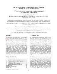
importance <str<strong>on</strong>g>for</str<strong>on</strong>g> EDL missi<strong>on</strong>s. Fig. 2 shows the global<br />
topography <str<strong>on</strong>g>of</str<strong>on</strong>g> the surface <str<strong>on</strong>g>of</str<strong>on</strong>g> Mars as a functi<strong>on</strong> <str<strong>on</strong>g>of</str<strong>on</strong>g><br />
surface elevati<strong>on</strong>. While the northern hemisphere is<br />
well below the reference zero altitude, the southern<br />
hemisphere is mostly above. The southern hemisphere<br />
is <strong>on</strong> average six kilometres higher than the northern<br />
<str<strong>on</strong>g>and</str<strong>on</strong>g> c<strong>on</strong>tains older areological <str<strong>on</strong>g>for</str<strong>on</strong>g>mati<strong>on</strong>s.<br />
Fig. 2. Maps <str<strong>on</strong>g>of</str<strong>on</strong>g> Mars global topography (Courtesy<br />
NASA/JPL-Caltech)<br />
Fig. 3 depicts some <str<strong>on</strong>g>of</str<strong>on</strong>g> the past l<str<strong>on</strong>g>and</str<strong>on</strong>g>ed science missi<strong>on</strong>s<br />
as well as the envisaged l<str<strong>on</strong>g>and</str<strong>on</strong>g>ing altitude <str<strong>on</strong>g>of</str<strong>on</strong>g> the Mars<br />
Science Laboratory. From this figure it can be seen that<br />
most <str<strong>on</strong>g>of</str<strong>on</strong>g> the past missi<strong>on</strong>s reached l<str<strong>on</strong>g>and</str<strong>on</strong>g>ing sites in<br />
modest <str<strong>on</strong>g>and</str<strong>on</strong>g> easy to reach altitudes. Regi<strong>on</strong>s <str<strong>on</strong>g>of</str<strong>on</strong>g> interest<br />
are, nevertheless, located <strong>on</strong> the ancient highl<str<strong>on</strong>g>and</str<strong>on</strong>g>s <str<strong>on</strong>g>of</str<strong>on</strong>g><br />
the south. However, l<str<strong>on</strong>g>and</str<strong>on</strong>g>ing sites above 4 km altitude<br />
are relatively small parts <str<strong>on</strong>g>of</str<strong>on</strong>g> the whole planet. L<str<strong>on</strong>g>and</str<strong>on</strong>g>ing<br />
missi<strong>on</strong>s should, there<str<strong>on</strong>g>for</str<strong>on</strong>g>e, aim <str<strong>on</strong>g>for</str<strong>on</strong>g> l<str<strong>on</strong>g>and</str<strong>on</strong>g>ing altitudes <str<strong>on</strong>g>of</str<strong>on</strong>g><br />
up to 4 km. The altitudes were measured by the Mars<br />
Orbiter Laser Altimeter (MOLA). Future missi<strong>on</strong>s are,<br />
there<str<strong>on</strong>g>for</str<strong>on</strong>g>e, likely to aim <str<strong>on</strong>g>for</str<strong>on</strong>g> l<str<strong>on</strong>g>and</str<strong>on</strong>g>ings below this height.<br />
Selecti<strong>on</strong> <str<strong>on</strong>g>of</str<strong>on</strong>g> a specific l<str<strong>on</strong>g>and</str<strong>on</strong>g>ing site depends <strong>on</strong> the<br />
goals <str<strong>on</strong>g>of</str<strong>on</strong>g> each individual missi<strong>on</strong> <str<strong>on</strong>g>and</str<strong>on</strong>g> imposes<br />
c<strong>on</strong>straints <strong>on</strong> the design <str<strong>on</strong>g>of</str<strong>on</strong>g> any l<str<strong>on</strong>g>and</str<strong>on</strong>g>ing system. An<br />
issue <str<strong>on</strong>g>of</str<strong>on</strong>g> importance is the hazard due to rocks in the<br />
l<str<strong>on</strong>g>and</str<strong>on</strong>g>ing area. The rock size <str<strong>on</strong>g>and</str<strong>on</strong>g> distributi<strong>on</strong> defines the<br />
l<str<strong>on</strong>g>and</str<strong>on</strong>g>ing system as well as the desired method <str<strong>on</strong>g>of</str<strong>on</strong>g><br />
l<str<strong>on</strong>g>and</str<strong>on</strong>g>ing (e.g. l<str<strong>on</strong>g>and</str<strong>on</strong>g>ing with a horiz<strong>on</strong>tal velocity<br />
comp<strong>on</strong>ent <str<strong>on</strong>g>and</str<strong>on</strong>g> a sled-like l<str<strong>on</strong>g>and</str<strong>on</strong>g>ing system).<br />
The above definiti<strong>on</strong> <str<strong>on</strong>g>of</str<strong>on</strong>g> the maximum target l<str<strong>on</strong>g>and</str<strong>on</strong>g>ing<br />
site altitude defines a lower limit <str<strong>on</strong>g>for</str<strong>on</strong>g> the deployment<br />
altitude. Assuming a parachute decelerati<strong>on</strong> <str<strong>on</strong>g>of</str<strong>on</strong>g> typical<br />
missi<strong>on</strong>s, the vertical distance covered during<br />
decelerati<strong>on</strong> is about 800 to 1000 m. Accounting <str<strong>on</strong>g>for</str<strong>on</strong>g><br />
deployment delays due to sensor uncertainties <str<strong>on</strong>g>and</str<strong>on</strong>g><br />
other sources, a loss <str<strong>on</strong>g>of</str<strong>on</strong>g> altitude <str<strong>on</strong>g>of</str<strong>on</strong>g> 1500 m should be<br />
assumed <str<strong>on</strong>g>for</str<strong>on</strong>g> the decelerati<strong>on</strong>. Combining these with the<br />
desired l<str<strong>on</strong>g>and</str<strong>on</strong>g>ing altitude the deployment must be<br />
per<str<strong>on</strong>g>for</str<strong>on</strong>g>med at least at an altitude above 5.5 km.<br />
From Fig. 1 it can be seen that <str<strong>on</strong>g>for</str<strong>on</strong>g> a parachute<br />
deployment at Mach 2.1, the minimum 5.5 km altitude<br />
can <strong>on</strong>ly be achieved by <str<strong>on</strong>g>entry</str<strong>on</strong>g> capsules with a ballistic<br />
coefficient less than 120 kg/m². The upper deployment<br />
altitude is not really limited despite the fact that higher<br />
altitudes at given Mach numbers are <strong>on</strong>ly reached <str<strong>on</strong>g>for</str<strong>on</strong>g><br />
lower ballistic pr<str<strong>on</strong>g>of</str<strong>on</strong>g>ile capsules. The upper limit <str<strong>on</strong>g>for</str<strong>on</strong>g> a<br />
30 kg/m² capsule would be 19 km. Such a capsule<br />
would very so<strong>on</strong> break through the upper dynamic<br />
pressure boundary <str<strong>on</strong>g>and</str<strong>on</strong>g> thus reach Mach 1.1 at a higher<br />
than allowed dynamic pressure. An upper limit <str<strong>on</strong>g>of</str<strong>on</strong>g> 19<br />
km was, nevertheless, selected as the parameter range<br />
<str<strong>on</strong>g>for</str<strong>on</strong>g> further analysis. Table 1 summarizes the selected<br />
boundary c<strong>on</strong>diti<strong>on</strong>s.<br />
Parameter<br />
Lower<br />
limit<br />
Upper<br />
limit<br />
Ballistic coefficient (<str<strong>on</strong>g>entry</str<strong>on</strong>g>) [kg/m²] 30 120<br />
Mach number [-] 1.1 2.1<br />
Dynamic pressure [Pa] 250 1200<br />
Deployment altitude [km] 5.5 19<br />
Table 1. Deployment c<strong>on</strong>diti<strong>on</strong>s <str<strong>on</strong>g>for</str<strong>on</strong>g> parachute/<str<strong>on</strong>g>auto</str<strong>on</strong>g>rotative<br />
EDL missi<strong>on</strong>s<br />
3 AUTO-ROTATION<br />
Fig. 3. Mars elevati<strong>on</strong> area distributi<strong>on</strong> [2]<br />
The <str<strong>on</strong>g>auto</str<strong>on</strong>g>-<str<strong>on</strong>g>rotati<strong>on</strong></str<strong>on</strong>g> principle is based <strong>on</strong> the<br />
aerodynamic lift generated by freely-rotating (i.e.<br />
unpowered) rotor blades in <str<strong>on</strong>g>for</str<strong>on</strong>g>ward <str<strong>on</strong>g>and</str<strong>on</strong>g> verticallydescending<br />
flight. Vehicles using this principle are<br />
termed <str<strong>on</strong>g>auto</str<strong>on</strong>g>gyros. Unlike helicopter rotor systems, the<br />
<str<strong>on</strong>g>auto</str<strong>on</strong>g>gyro rotor is mechanically simple <str<strong>on</strong>g>and</str<strong>on</strong>g> the blades<br />
do not necessarily require cyclic pitch c<strong>on</strong>trol.<br />
Autogyros have been developed <str<strong>on</strong>g>and</str<strong>on</strong>g> flown with a
moveable axis without cyclic pitch c<strong>on</strong>trol or a fixed<br />
rotor axis with cyclic pitch c<strong>on</strong>trol.<br />
Auto-<str<strong>on</strong>g>rotati<strong>on</strong></str<strong>on</strong>g>al l<str<strong>on</strong>g>and</str<strong>on</strong>g>ings <str<strong>on</strong>g>of</str<strong>on</strong>g> various types <str<strong>on</strong>g>of</str<strong>on</strong>g> vehicle<br />
have been c<strong>on</strong>ducted in terrestrial free flight trials <str<strong>on</strong>g>and</str<strong>on</strong>g><br />
wind tunnels tests, <str<strong>on</strong>g>and</str<strong>on</strong>g>, practically, in emergency<br />
situati<strong>on</strong>s with helicopters since the 1920s. Interest in<br />
<str<strong>on</strong>g>auto</str<strong>on</strong>g>-<str<strong>on</strong>g>rotati<strong>on</strong></str<strong>on</strong>g> l<str<strong>on</strong>g>and</str<strong>on</strong>g>ing systems re-emerged in the 1950s<br />
with schemes <str<strong>on</strong>g>for</str<strong>on</strong>g> the recovery <str<strong>on</strong>g>of</str<strong>on</strong>g> air-launched<br />
payloads, rocket boosters <str<strong>on</strong>g>and</str<strong>on</strong>g> manned lifting bodies<br />
<str<strong>on</strong>g>and</str<strong>on</strong>g> capsules as an alternative to parachutes <str<strong>on</strong>g>and</str<strong>on</strong>g><br />
parafoils. In the event <strong>on</strong>ly parachutes were adopted<br />
<str<strong>on</strong>g>for</str<strong>on</strong>g> the retrieval <str<strong>on</strong>g>of</str<strong>on</strong>g> re-<str<strong>on</strong>g>entry</str<strong>on</strong>g> vehicles; rotor systems<br />
being c<strong>on</strong>sidered difficult to develop, especially if<br />
deployed during the re<str<strong>on</strong>g>entry</str<strong>on</strong>g> phase (aerothermodynamic<br />
technology development was required), too complex<br />
mechanically <str<strong>on</strong>g>and</str<strong>on</strong>g> difficult to install.<br />
The most extensive investigati<strong>on</strong> <str<strong>on</strong>g>of</str<strong>on</strong>g> <str<strong>on</strong>g>auto</str<strong>on</strong>g>-<str<strong>on</strong>g>rotati<strong>on</strong></str<strong>on</strong>g><br />
l<str<strong>on</strong>g>and</str<strong>on</strong>g>ing systems was d<strong>on</strong>e by Kaman Aircraft<br />
Corporati<strong>on</strong> in the period mid-1957 to mid-1967. At<br />
that time Kaman was interested in developing these<br />
systems <str<strong>on</strong>g>for</str<strong>on</strong>g> air-launched payloads but suggested that<br />
the system was applicable to the terrestrial recovery <str<strong>on</strong>g>of</str<strong>on</strong>g><br />
space vehicles such as manned re-<str<strong>on</strong>g>entry</str<strong>on</strong>g> capsules [3].<br />
Other proposals <str<strong>on</strong>g>for</str<strong>on</strong>g> <str<strong>on</strong>g>auto</str<strong>on</strong>g>-<str<strong>on</strong>g>rotati<strong>on</strong></str<strong>on</strong>g> EDL systems also<br />
c<strong>on</strong>sidered inflatable rotors [4, 5].<br />
square root <str<strong>on</strong>g>of</str<strong>on</strong>g> the total l<str<strong>on</strong>g>and</str<strong>on</strong>g>ed mass (l<str<strong>on</strong>g>and</str<strong>on</strong>g>ing mass <str<strong>on</strong>g>and</str<strong>on</strong>g><br />
mass <str<strong>on</strong>g>of</str<strong>on</strong>g> <str<strong>on</strong>g>descent</str<strong>on</strong>g> <str<strong>on</strong>g>and</str<strong>on</strong>g> l<str<strong>on</strong>g>and</str<strong>on</strong>g>ing system).<br />
The main c<strong>on</strong>siderati<strong>on</strong>s <str<strong>on</strong>g>for</str<strong>on</strong>g> initial rotor sizing can be<br />
summarized as follows:<br />
• The rotor diameter is basically determined by<br />
the desired vertical <str<strong>on</strong>g>descent</str<strong>on</strong>g> velocity.<br />
• The desired vertical <str<strong>on</strong>g>descent</str<strong>on</strong>g> velocity 10-20<br />
m/s (ESA Specificati<strong>on</strong>) is high. However,<br />
glide operati<strong>on</strong>s with a <str<strong>on</strong>g>for</str<strong>on</strong>g>ward speed<br />
comp<strong>on</strong>ent as well as l<str<strong>on</strong>g>and</str<strong>on</strong>g>ing flare allow<br />
significant reducti<strong>on</strong>s <str<strong>on</strong>g>of</str<strong>on</strong>g> sink rate compared to<br />
vertical <str<strong>on</strong>g>descent</str<strong>on</strong>g>.<br />
• Blade geometry (chord length, aspect ratio) is<br />
determined by the number <str<strong>on</strong>g>of</str<strong>on</strong>g> blades <str<strong>on</strong>g>and</str<strong>on</strong>g> the<br />
desired rotor solidity.<br />
• Maximum permissible rotor RPM is<br />
determined by rotor blade tip Mach number<br />
limitati<strong>on</strong> (Mach 0.8 … 0.9).<br />
A comparatively simple calculati<strong>on</strong> to determine rotor<br />
sizes to meet the requirements specified in the<br />
introducti<strong>on</strong> to this paper can be based <strong>on</strong> estimates <str<strong>on</strong>g>of</str<strong>on</strong>g><br />
the per<str<strong>on</strong>g>for</str<strong>on</strong>g>mance <str<strong>on</strong>g>of</str<strong>on</strong>g> a rotor system by applying<br />
momentum theory <str<strong>on</strong>g>for</str<strong>on</strong>g> an actuator disc model <str<strong>on</strong>g>of</str<strong>on</strong>g> a<br />
uni<str<strong>on</strong>g>for</str<strong>on</strong>g>mly loaded rotor. The <str<strong>on</strong>g>auto</str<strong>on</strong>g>-<str<strong>on</strong>g>rotati<strong>on</strong></str<strong>on</strong>g> per<str<strong>on</strong>g>for</str<strong>on</strong>g>mance<br />
may be c<strong>on</strong>sidered in terms <str<strong>on</strong>g>of</str<strong>on</strong>g> a drag coefficient based<br />
<strong>on</strong> rotor disc area <str<strong>on</strong>g>and</str<strong>on</strong>g> vertical <str<strong>on</strong>g>descent</str<strong>on</strong>g> velocity (leading<br />
to a drag coefficient CD ≈ 1.1).<br />
C<strong>on</strong>sidering a vertical <str<strong>on</strong>g>descent</str<strong>on</strong>g>, the c<strong>on</strong>diti<strong>on</strong> that the<br />
<str<strong>on</strong>g>auto</str<strong>on</strong>g>-<str<strong>on</strong>g>rotati<strong>on</strong></str<strong>on</strong>g> system drag should equal weight <str<strong>on</strong>g>for</str<strong>on</strong>g> the<br />
maximum permissible <str<strong>on</strong>g>descent</str<strong>on</strong>g> velocity at the elevati<strong>on</strong><br />
<str<strong>on</strong>g>of</str<strong>on</strong>g> the l<str<strong>on</strong>g>and</str<strong>on</strong>g>ing surface leads to the following simple<br />
<str<strong>on</strong>g>for</str<strong>on</strong>g>mula:<br />
1<br />
d =<br />
V<br />
8 ⋅ m ⋅ g<br />
π ⋅ ⋅ ρ<br />
C D<br />
(2)<br />
where d = rotor diameter, V = <str<strong>on</strong>g>descent</str<strong>on</strong>g> velocity, m =<br />
l<str<strong>on</strong>g>and</str<strong>on</strong>g>ing mass including rotor system, g = gravitati<strong>on</strong>al<br />
accelerati<strong>on</strong>, CD = drag coefficient, <str<strong>on</strong>g>and</str<strong>on</strong>g> ρ =<br />
atmospheric density<br />
There<str<strong>on</strong>g>for</str<strong>on</strong>g>e, the rotor diameter required is inversely<br />
proporti<strong>on</strong>al to the maximum permissible vertical<br />
speed at l<str<strong>on</strong>g>and</str<strong>on</strong>g>ing elevati<strong>on</strong> <str<strong>on</strong>g>and</str<strong>on</strong>g> proporti<strong>on</strong>al to the<br />
Fig. 4. Required Rotor Diameter vs. Total L<str<strong>on</strong>g>and</str<strong>on</strong>g>ing<br />
Mass <str<strong>on</strong>g>for</str<strong>on</strong>g> vertical <str<strong>on</strong>g>descent</str<strong>on</strong>g> speeds <str<strong>on</strong>g>of</str<strong>on</strong>g> 10 m/s <str<strong>on</strong>g>and</str<strong>on</strong>g> 20 m/s<br />
(Mars c<strong>on</strong>diti<strong>on</strong>s 0 m MOLA)<br />
Assuming a single rotor system, a variati<strong>on</strong> <str<strong>on</strong>g>of</str<strong>on</strong>g> key<br />
parameters reveals the dependencies shown in Figs. 4<br />
<str<strong>on</strong>g>and</str<strong>on</strong>g> 5, the <str<strong>on</strong>g>for</str<strong>on</strong>g>mer showing the required rotor diameter<br />
versus total l<str<strong>on</strong>g>and</str<strong>on</strong>g>ing mass <str<strong>on</strong>g>for</str<strong>on</strong>g> a vertical <str<strong>on</strong>g>descent</str<strong>on</strong>g> speed<br />
range <str<strong>on</strong>g>of</str<strong>on</strong>g> 10 to 20 m/s under Mars c<strong>on</strong>diti<strong>on</strong>s at 0 m<br />
MOLA.<br />
Figure 5 shows the n<strong>on</strong>-linear increase <str<strong>on</strong>g>of</str<strong>on</strong>g> the rotor<br />
diameter with increasing EDL system mass. The shape<br />
<str<strong>on</strong>g>of</str<strong>on</strong>g> the curve allows the c<strong>on</strong>clusi<strong>on</strong> that the relative<br />
weight <str<strong>on</strong>g>and</str<strong>on</strong>g> size required <str<strong>on</strong>g>for</str<strong>on</strong>g> rotor system based EDL<br />
system tends to favour such <str<strong>on</strong>g>applicati<strong>on</strong></str<strong>on</strong>g>s towards<br />
heavier l<str<strong>on</strong>g>and</str<strong>on</strong>g>er masses.
4.1 Transiti<strong>on</strong> from Entry to Descent<br />
Fig. 5. Rotor Diameter vs. Vertical Descent Velocity<br />
<str<strong>on</strong>g>for</str<strong>on</strong>g> Mars <str<strong>on</strong>g>and</str<strong>on</strong>g> Earth (Mars c<strong>on</strong>diti<strong>on</strong>s 0 m MOLA)<br />
4 APPLICATION OF AUTO-ROTATION FOR<br />
ENTRY, DESCENT AND LANDING<br />
The state <str<strong>on</strong>g>of</str<strong>on</strong>g> <str<strong>on</strong>g>auto</str<strong>on</strong>g>-<str<strong>on</strong>g>rotati<strong>on</strong></str<strong>on</strong>g> can be applied to EDL<br />
missi<strong>on</strong>s. In c<strong>on</strong>trast to classical EDL missi<strong>on</strong>s, the<br />
missi<strong>on</strong> sequence <str<strong>on</strong>g>of</str<strong>on</strong>g> an <str<strong>on</strong>g>auto</str<strong>on</strong>g>-<str<strong>on</strong>g>rotati<strong>on</strong></str<strong>on</strong>g> system can be as<br />
follows:<br />
• <str<strong>on</strong>g>entry</str<strong>on</strong>g><br />
• release <str<strong>on</strong>g>of</str<strong>on</strong>g> rotor cover<br />
• deployment <str<strong>on</strong>g>of</str<strong>on</strong>g> rotor, establishment <str<strong>on</strong>g>of</str<strong>on</strong>g> <str<strong>on</strong>g>auto</str<strong>on</strong>g><str<strong>on</strong>g>rotati<strong>on</strong></str<strong>on</strong>g><br />
state <str<strong>on</strong>g>and</str<strong>on</strong>g> decelerati<strong>on</strong><br />
• release <str<strong>on</strong>g>of</str<strong>on</strong>g> heat shield (assuming traditi<strong>on</strong>al<br />
heat shield technology)<br />
• glide phase<br />
• flare<br />
• touchdown<br />
For a missi<strong>on</strong> capable <str<strong>on</strong>g>of</str<strong>on</strong>g> meeting future requirements it<br />
will almost certainly be m<str<strong>on</strong>g>and</str<strong>on</strong>g>atory to provide full<br />
hazard avoidance capability <str<strong>on</strong>g>and</str<strong>on</strong>g>, there<str<strong>on</strong>g>for</str<strong>on</strong>g>e, the<br />
complete chain <str<strong>on</strong>g>of</str<strong>on</strong>g> EDL events should be designed to<br />
support guided flight operati<strong>on</strong>. In order to ensure this<br />
type <str<strong>on</strong>g>of</str<strong>on</strong>g> operati<strong>on</strong>, the orientati<strong>on</strong> <str<strong>on</strong>g>of</str<strong>on</strong>g> the rotor disc <str<strong>on</strong>g>of</str<strong>on</strong>g><br />
the deployed c<strong>on</strong>figurati<strong>on</strong> must be fully c<strong>on</strong>trollable.<br />
There<str<strong>on</strong>g>for</str<strong>on</strong>g>e, an <str<strong>on</strong>g>auto</str<strong>on</strong>g>-<str<strong>on</strong>g>rotati<strong>on</strong></str<strong>on</strong>g> based EDL system will<br />
have a high degree <str<strong>on</strong>g>of</str<strong>on</strong>g> <str<strong>on</strong>g>auto</str<strong>on</strong>g>nomy <str<strong>on</strong>g>and</str<strong>on</strong>g>, when equipped<br />
with a dedicated sensor suite <str<strong>on</strong>g>and</str<strong>on</strong>g> a modern avi<strong>on</strong>ics<br />
system, it will have the following features:<br />
• <str<strong>on</strong>g>auto</str<strong>on</strong>g>nomous deployment <str<strong>on</strong>g>of</str<strong>on</strong>g> the rotor system as<br />
comm<str<strong>on</strong>g>and</str<strong>on</strong>g>ed by the guidance system<br />
• guided flight to a dedicated target point<br />
• <str<strong>on</strong>g>auto</str<strong>on</strong>g>nomous per<str<strong>on</strong>g>for</str<strong>on</strong>g>mance <str<strong>on</strong>g>of</str<strong>on</strong>g> hazard avoidance<br />
manoeuvres (selecti<strong>on</strong> <str<strong>on</strong>g>of</str<strong>on</strong>g> new target point)<br />
• flare manoeuvre to per<str<strong>on</strong>g>for</str<strong>on</strong>g>m a s<str<strong>on</strong>g>of</str<strong>on</strong>g>t <str<strong>on</strong>g>and</str<strong>on</strong>g> precise<br />
l<str<strong>on</strong>g>and</str<strong>on</strong>g>ing at the selected locati<strong>on</strong><br />
Transiti<strong>on</strong> from <str<strong>on</strong>g>entry</str<strong>on</strong>g> to <str<strong>on</strong>g>descent</str<strong>on</strong>g> takes place when the<br />
rotor is deployed. This is assumed to happen at<br />
Mach 2. Past missi<strong>on</strong>s tend to release the parachute at<br />
smaller Mach numbers but in order to reach l<str<strong>on</strong>g>and</str<strong>on</strong>g>ing<br />
sites at a high altitude an earlier deployment at higher<br />
Mach numbers is necessary. Rotor deployment is<br />
designed to take place at Mach 2 <str<strong>on</strong>g>and</str<strong>on</strong>g> at an altitude <str<strong>on</strong>g>of</str<strong>on</strong>g><br />
approximately 10 km. The required target l<str<strong>on</strong>g>and</str<strong>on</strong>g>ing<br />
velocity is in the range from 10 m/s to 20 m/s. Fig. 6<br />
shows the velocity-altitude diagram <str<strong>on</strong>g>for</str<strong>on</strong>g> the transiti<strong>on</strong> to<br />
both l<str<strong>on</strong>g>and</str<strong>on</strong>g>ing velocities, the solid red lines indicating<br />
the velocity pr<str<strong>on</strong>g>of</str<strong>on</strong>g>iles <str<strong>on</strong>g>for</str<strong>on</strong>g> 10 m/s <str<strong>on</strong>g>and</str<strong>on</strong>g> 20 m/s l<str<strong>on</strong>g>and</str<strong>on</strong>g>ing<br />
speeds. It can be seen that after <str<strong>on</strong>g>entry</str<strong>on</strong>g> the capsule<br />
encounters the regi<strong>on</strong> <str<strong>on</strong>g>of</str<strong>on</strong>g> parachute/rotor deployment<br />
(shaded z<strong>on</strong>e). After deployment the velocity decreases<br />
until the vehicle achieves steady state <str<strong>on</strong>g>descent</str<strong>on</strong>g>.<br />
Depending <strong>on</strong> the target l<str<strong>on</strong>g>and</str<strong>on</strong>g>ing speed, the vehicle<br />
either decelerates faster at higher altitudes or slower at<br />
lower altitudes. The dotted line shows the <str<strong>on</strong>g>entry</str<strong>on</strong>g><br />
trajectory to touchdown if no decelerati<strong>on</strong> device is<br />
deployed. The final <str<strong>on</strong>g>descent</str<strong>on</strong>g> trajectories with 10 m/s<br />
<str<strong>on</strong>g>and</str<strong>on</strong>g> 20 m/s in this figure are assumed to be vertical.<br />
Altitude [km]<br />
25<br />
20<br />
15<br />
10<br />
5<br />
Mach 1 Mach 2 Mach 3 Mach 4<br />
0<br />
0 100 200 300 400 500 600 700 800 900 1000<br />
Velocity [m/s]<br />
Fig. 6. Altitude vs. Velocity <str<strong>on</strong>g>for</str<strong>on</strong>g> reference missi<strong>on</strong><br />
It was found during first missi<strong>on</strong> design iterati<strong>on</strong>s that<br />
it might be beneficial to use the lifting capabilities <str<strong>on</strong>g>of</str<strong>on</strong>g><br />
the rotor even during deployment. However, at present<br />
it is not clear how this would interfere with the<br />
acquisiti<strong>on</strong> <str<strong>on</strong>g>of</str<strong>on</strong>g> <str<strong>on</strong>g>auto</str<strong>on</strong>g>-<str<strong>on</strong>g>rotati<strong>on</strong></str<strong>on</strong>g> <str<strong>on</strong>g>and</str<strong>on</strong>g> what the impacts will<br />
be <strong>on</strong> c<strong>on</strong>trollability. There<str<strong>on</strong>g>for</str<strong>on</strong>g>e, it was assumed <str<strong>on</strong>g>for</str<strong>on</strong>g> the<br />
purposes <str<strong>on</strong>g>of</str<strong>on</strong>g> analysis, that during rotor deployment, the<br />
rotor disc will be perpendicular to the free stream <str<strong>on</strong>g>and</str<strong>on</strong>g><br />
hence to the general moti<strong>on</strong> <str<strong>on</strong>g>of</str<strong>on</strong>g> the vehicle. Glide <str<strong>on</strong>g>and</str<strong>on</strong>g><br />
c<strong>on</strong>trolled flight will take place after the vehicle has<br />
been decelerated <str<strong>on</strong>g>and</str<strong>on</strong>g> a steady <str<strong>on</strong>g>descent</str<strong>on</strong>g> state has been<br />
achieved.
4.2 Glide Phase<br />
During the glide phase it is possible to guide the <str<strong>on</strong>g>auto</str<strong>on</strong>g><str<strong>on</strong>g>rotati<strong>on</strong></str<strong>on</strong>g><br />
system in a desired directi<strong>on</strong>. Figure 7 shows<br />
the theoretically possible down range capability. For<br />
example, the l<str<strong>on</strong>g>and</str<strong>on</strong>g>er could achieve a maximum down<br />
range <str<strong>on</strong>g>of</str<strong>on</strong>g> 28 km from an initial height <str<strong>on</strong>g>of</str<strong>on</strong>g> 8 km to reach<br />
a desired l<str<strong>on</strong>g>and</str<strong>on</strong>g>ing site at an elevati<strong>on</strong> <str<strong>on</strong>g>of</str<strong>on</strong>g> 0 km assuming<br />
a lift/drag (L/D) ratio <str<strong>on</strong>g>of</str<strong>on</strong>g> 3.5.<br />
5<br />
4.5<br />
10<br />
20<br />
30<br />
40<br />
Fig. 8 shows the down range capability <str<strong>on</strong>g>of</str<strong>on</strong>g> an <str<strong>on</strong>g>auto</str<strong>on</strong>g><str<strong>on</strong>g>rotati<strong>on</strong></str<strong>on</strong>g><br />
system <str<strong>on</strong>g>for</str<strong>on</strong>g> a ballistic coefficient <str<strong>on</strong>g>of</str<strong>on</strong>g> 0.8 kg/m²<br />
<str<strong>on</strong>g>and</str<strong>on</strong>g> an 8 km altitude difference. It can be seen that,<br />
depending <strong>on</strong> the L/D ratio at lower wind velocities,<br />
flight against the wind is possible. When the wind<br />
increases, the down range capability is lost <str<strong>on</strong>g>and</str<strong>on</strong>g> even<br />
becomes negative. Changing the L/D ratio actively<br />
during flight by altering the angle-<str<strong>on</strong>g>of</str<strong>on</strong>g>-attack has a<br />
beneficial effect <strong>on</strong>ly <strong>on</strong> the down range if the drag is<br />
not increased.<br />
4.3 Flare <str<strong>on</strong>g>and</str<strong>on</strong>g> Touchdown<br />
L/D ratio [-]<br />
4<br />
3.5<br />
3<br />
2.5<br />
2<br />
1.5<br />
1<br />
0.5<br />
10<br />
0<br />
0 1 2 3 4 5 6 7 8 9 10<br />
Altitude Difference [km]<br />
Fig. 7. Down range (km) capability a as functi<strong>on</strong> <str<strong>on</strong>g>of</str<strong>on</strong>g><br />
altitude difference <str<strong>on</strong>g>and</str<strong>on</strong>g> L/D ratio<br />
However, two effects need to be c<strong>on</strong>sidered. Firstly, if<br />
it is intended to l<str<strong>on</strong>g>and</str<strong>on</strong>g> at higher altitudes, say 4 km, the<br />
possible achievable down range is reduced to 14 km.<br />
Sec<strong>on</strong>dly, if winds are encountered (which is most<br />
likely), then the down range capability might also be<br />
reduced since the wind alters the angle-<str<strong>on</strong>g>of</str<strong>on</strong>g>-attack <str<strong>on</strong>g>and</str<strong>on</strong>g><br />
hence the L/D ratio. Furthermore, it might be necessary<br />
to per<str<strong>on</strong>g>for</str<strong>on</strong>g>m a hazard avoidance manoeuvre, which,<br />
depending <strong>on</strong> the missi<strong>on</strong> specific needs, imposes a<br />
minimum cross <str<strong>on</strong>g>and</str<strong>on</strong>g> down range requirement<br />
10<br />
20<br />
30<br />
10<br />
20<br />
L<str<strong>on</strong>g>and</str<strong>on</strong>g>ing can be per<str<strong>on</strong>g>for</str<strong>on</strong>g>med in two different ways:<br />
vertically or horiz<strong>on</strong>tally. In the case a vertical l<str<strong>on</strong>g>and</str<strong>on</strong>g>ing<br />
shall be per<str<strong>on</strong>g>for</str<strong>on</strong>g>med the rotor disc is tilted such, that any<br />
lateral wind induced movement wrt the ground is<br />
mitigated <str<strong>on</strong>g>and</str<strong>on</strong>g> the vehicle in turn <str<strong>on</strong>g>descent</str<strong>on</strong>g>s purely<br />
vertically. Of course, above a certain wind speed this<br />
strategy will lead again to a lateral movement <str<strong>on</strong>g>of</str<strong>on</strong>g> the<br />
l<str<strong>on</strong>g>and</str<strong>on</strong>g>er. If a horiz<strong>on</strong>tal l<str<strong>on</strong>g>and</str<strong>on</strong>g>ing is to be per<str<strong>on</strong>g>for</str<strong>on</strong>g>med a flare<br />
manoeuvre must be per<str<strong>on</strong>g>for</str<strong>on</strong>g>med that changes the<br />
velocity directi<strong>on</strong> such, that the trajectory hits the<br />
ground nearly tangentially. The flare manoeuvre can be<br />
per<str<strong>on</strong>g>for</str<strong>on</strong>g>med in two ways:<br />
• by pitching up the whole vehicle <str<strong>on</strong>g>and</str<strong>on</strong>g> thus<br />
reducing vertical speed while simultaneously<br />
decreasing lateral speed (maximum horiz<strong>on</strong>tal<br />
velocity comp<strong>on</strong>ent reducti<strong>on</strong> will be<br />
achieved when pitching against the wind<br />
directi<strong>on</strong>), or<br />
• by increasing the collective pitch angle <str<strong>on</strong>g>of</str<strong>on</strong>g> the<br />
rotor blades.<br />
5 AN INFLATABLE AUTO-ROTATION<br />
SYSTEM CONCEPT FOR EDL ON MARS<br />
Glide Ratio [-]<br />
5<br />
4.5<br />
4<br />
3.5<br />
3<br />
2.5<br />
2<br />
1.5<br />
1<br />
30<br />
20<br />
10<br />
20<br />
10<br />
10<br />
0<br />
0<br />
-10<br />
0.5<br />
0 5 10 15 20 25 30<br />
Wind Speed [m/s]<br />
Fig. 8. Down range (km) as a functi<strong>on</strong> <str<strong>on</strong>g>of</str<strong>on</strong>g> L/D ratio <str<strong>on</strong>g>and</str<strong>on</strong>g><br />
wind speed (ΔH = 8 km, β = 0.8 kg/m²)<br />
0<br />
-10<br />
-20<br />
-30<br />
-40<br />
-20<br />
-10<br />
-30<br />
-60<br />
-50<br />
5.1 Design<br />
Two basic rotor c<strong>on</strong>cepts were examined using data<br />
derived from Figs. 4 <str<strong>on</strong>g>and</str<strong>on</strong>g> 5, namely, a “rigid” rotor<br />
system with telescopic blades <str<strong>on</strong>g>and</str<strong>on</strong>g> a fully inflatable<br />
rotor system which is shown in Fig. 9.<br />
The potential advantage <str<strong>on</strong>g>of</str<strong>on</strong>g> the rigid rotor system might<br />
be seen in the fact that there exists a wealth <str<strong>on</strong>g>of</str<strong>on</strong>g><br />
experience <strong>on</strong> the actual aerodynamic functi<strong>on</strong> <str<strong>on</strong>g>of</str<strong>on</strong>g> rotor<br />
systems made <str<strong>on</strong>g>of</str<strong>on</strong>g> rigid materials, at least <str<strong>on</strong>g>for</str<strong>on</strong>g> terrestrial<br />
<str<strong>on</strong>g>applicati<strong>on</strong></str<strong>on</strong>g>s. This also includes various rotor folding<br />
mechanisms to reduce hangar space required by larger<br />
helicopters. Of course, such folding mechanisms can in<br />
no way be c<strong>on</strong>sidered fully comparable to the<br />
requirements <str<strong>on</strong>g>for</str<strong>on</strong>g> a rotor system to be unfolded in flight<br />
<strong>on</strong> Mars. On the other h<str<strong>on</strong>g>and</str<strong>on</strong>g>, no actual experience exists<br />
regarding the aerodynamic operati<strong>on</strong> <str<strong>on</strong>g>and</str<strong>on</strong>g> per<str<strong>on</strong>g>for</str<strong>on</strong>g>mance
<str<strong>on</strong>g>of</str<strong>on</strong>g> inflatable rotor systems. However, inflatable fixed<br />
wing piloted <str<strong>on</strong>g>and</str<strong>on</strong>g> remotely-piloted aircraft have been<br />
dem<strong>on</strong>strated in actual flight under Earth c<strong>on</strong>diti<strong>on</strong>s.<br />
Inflatable<br />
Deployment Ring<br />
Fig. 9. Inflatable rotor system c<strong>on</strong>cept<br />
A detailed trade-<str<strong>on</strong>g>of</str<strong>on</strong>g>f between these two basic opti<strong>on</strong>s<br />
clearly favoured the inflatable system both in terms <str<strong>on</strong>g>of</str<strong>on</strong>g><br />
mass <str<strong>on</strong>g>and</str<strong>on</strong>g> packaging. The rigid rotor system proved<br />
much heavier than the inflatable system <str<strong>on</strong>g>and</str<strong>on</strong>g> had a mass<br />
almost as much as the capsule it was intended to l<str<strong>on</strong>g>and</str<strong>on</strong>g>.<br />
The inflatable rotor mass/l<str<strong>on</strong>g>and</str<strong>on</strong>g>ed mass fracti<strong>on</strong> is <str<strong>on</strong>g>of</str<strong>on</strong>g> the<br />
order <str<strong>on</strong>g>of</str<strong>on</strong>g> 15%. The size <str<strong>on</strong>g>of</str<strong>on</strong>g> the stowed rigid rotors<br />
required them to be housed in a tail-like fairing behind<br />
the <str<strong>on</strong>g>entry</str<strong>on</strong>g> vehicle, whereas the deflated inflatable rotor<br />
was stowed in a flat circular compartment within the<br />
capsule’s back shell. The inflatable rotor was selected<br />
as the more promising c<strong>on</strong>cept.<br />
5.2 Evaluati<strong>on</strong><br />
Capsule<br />
Rotor C<strong>on</strong>trol<br />
Swashplate<br />
Inflatable<br />
Rotor Blade<br />
For the evaluati<strong>on</strong> <str<strong>on</strong>g>of</str<strong>on</strong>g> the inflatable <str<strong>on</strong>g>auto</str<strong>on</strong>g>-<str<strong>on</strong>g>rotati<strong>on</strong></str<strong>on</strong>g> D&L<br />
system several design opti<strong>on</strong>s were established <str<strong>on</strong>g>and</str<strong>on</strong>g> its<br />
per<str<strong>on</strong>g>for</str<strong>on</strong>g>mance evaluated with dedicated simulati<strong>on</strong><br />
s<str<strong>on</strong>g>of</str<strong>on</strong>g>tware. Table 2 gives an overview about the opti<strong>on</strong>s<br />
which are based up<strong>on</strong> target l<str<strong>on</strong>g>and</str<strong>on</strong>g>ed mass <str<strong>on</strong>g>and</str<strong>on</strong>g> vertical<br />
l<str<strong>on</strong>g>and</str<strong>on</strong>g>ing velocity.<br />
L<str<strong>on</strong>g>and</str<strong>on</strong>g>ed Mass [kg]<br />
20 100 200<br />
L<str<strong>on</strong>g>and</str<strong>on</strong>g>ing 10 Opti<strong>on</strong> 1 Opti<strong>on</strong> 3 Opti<strong>on</strong> 5<br />
Velocity [m/s] 20 Opti<strong>on</strong> 2 Opti<strong>on</strong> 4 Opti<strong>on</strong> 6<br />
Table 2. System opti<strong>on</strong> designati<strong>on</strong>s<br />
For each opti<strong>on</strong> a design was set-up assuming a rotor<br />
deployment altitude <str<strong>on</strong>g>of</str<strong>on</strong>g> 10041 m at a flight path<br />
Velocity <str<strong>on</strong>g>of</str<strong>on</strong>g> 383.45 m/s <str<strong>on</strong>g>and</str<strong>on</strong>g> a flight path angle <str<strong>on</strong>g>of</str<strong>on</strong>g> -28.4<br />
deg. The resulting designs are given within Table 3.<br />
Opti<strong>on</strong> 1 2 3 4 5 6<br />
Entry Capsule<br />
Diameter [m]<br />
0.75 0.62 1.63 1.37 2.36 1.93<br />
Solidity [-] 0.10 0.15 0.10 0.15 0.10 0.15<br />
Rotor<br />
Diameter [m]<br />
14.87 6.20 32.60 13.50 47.12 19.20<br />
Diameter<br />
Ratio [-]<br />
0.05 0.10 0.05 0.10 0.05 0.10<br />
Blade Pitch<br />
Angle [deg]<br />
2 4 2 4 1 4<br />
Entry<br />
Mass [kg]<br />
41.9 29.4 201.5 140.9 420.9 281.7<br />
Rotor Cover<br />
Mass [kg]<br />
0.6 0.4 3.0 2.1 6.3 4.2<br />
Heatshield<br />
Mass [kg]<br />
6.3 4.4 30.2 21.1 63.1 42.3<br />
Rotor System<br />
Mass [kg]<br />
15.0 4.6 68.2 17.6 151.4 35.2<br />
L<str<strong>on</strong>g>and</str<strong>on</strong>g>ed<br />
Mass [kg]<br />
20 20 100 100 200 200<br />
Table 3. Auto-Rotati<strong>on</strong> system opti<strong>on</strong>s<br />
Since the above opti<strong>on</strong>s were derived with a specific<br />
vertical l<str<strong>on</strong>g>and</str<strong>on</strong>g>ing velocity requirement Fig 10 shows the<br />
resulting vertical l<str<strong>on</strong>g>and</str<strong>on</strong>g>ing velocity <str<strong>on</strong>g>of</str<strong>on</strong>g> the different<br />
opti<strong>on</strong>s <str<strong>on</strong>g>for</str<strong>on</strong>g> various wind c<strong>on</strong>diti<strong>on</strong>s.<br />
Vertical L<str<strong>on</strong>g>and</str<strong>on</strong>g>ing Velocity [m/s]<br />
25.00<br />
20.00<br />
15.00<br />
10.00<br />
5.00<br />
0.00<br />
Opti<strong>on</strong><br />
1<br />
Opti<strong>on</strong><br />
2<br />
Opti<strong>on</strong><br />
3<br />
Opti<strong>on</strong><br />
4<br />
Opti<strong>on</strong><br />
5<br />
Opti<strong>on</strong><br />
6<br />
No Wind<br />
Medium Tail Wind<br />
Medium Head Wind<br />
Fig. 10. L<str<strong>on</strong>g>and</str<strong>on</strong>g>ing velocity <str<strong>on</strong>g>of</str<strong>on</strong>g> a vertical l<str<strong>on</strong>g>and</str<strong>on</strong>g>ing, <str<strong>on</strong>g>auto</str<strong>on</strong>g><str<strong>on</strong>g>rotati<strong>on</strong></str<strong>on</strong>g><br />
c<strong>on</strong>figurati<strong>on</strong><br />
It can be seen, that the velocity decreases slightly when<br />
moderate wind acts <strong>on</strong> the vehicle. This is a result <str<strong>on</strong>g>of</str<strong>on</strong>g><br />
the capability <str<strong>on</strong>g>of</str<strong>on</strong>g> the <str<strong>on</strong>g>auto</str<strong>on</strong>g>-<str<strong>on</strong>g>rotati<strong>on</strong></str<strong>on</strong>g> l<str<strong>on</strong>g>and</str<strong>on</strong>g>er to glide<br />
against moderate winds <str<strong>on</strong>g>and</str<strong>on</strong>g> <str<strong>on</strong>g>descent</str<strong>on</strong>g> purely vertically.<br />
This is definitely an advantage to parachute based<br />
missi<strong>on</strong>s, which need complex thruster set-ups <str<strong>on</strong>g>for</str<strong>on</strong>g><br />
wind mitigati<strong>on</strong> while within the <str<strong>on</strong>g>auto</str<strong>on</strong>g>-<str<strong>on</strong>g>rotati<strong>on</strong></str<strong>on</strong>g> system<br />
this capability is already included.<br />
Figure 11 shows the resulting lateral velocity if a flare<br />
l<str<strong>on</strong>g>and</str<strong>on</strong>g>ing is per<str<strong>on</strong>g>for</str<strong>on</strong>g>med. Flare l<str<strong>on</strong>g>and</str<strong>on</strong>g>ings reduces the<br />
l<str<strong>on</strong>g>and</str<strong>on</strong>g>ing velocity significantly. It is to be noted, that<br />
head <str<strong>on</strong>g>and</str<strong>on</strong>g> tail wind refers to the wind c<strong>on</strong>diti<strong>on</strong> during
the gliding flight. The l<str<strong>on</strong>g>and</str<strong>on</strong>g>ing is always per<str<strong>on</strong>g>for</str<strong>on</strong>g>med<br />
against the wind directi<strong>on</strong>.<br />
Flare L<str<strong>on</strong>g>and</str<strong>on</strong>g>ing Velocity [m/s]<br />
6.00<br />
5.00<br />
4.00<br />
3.00<br />
2.00<br />
1.00<br />
0.00<br />
-1.00<br />
-2.00<br />
Opti<strong>on</strong><br />
1<br />
Opti<strong>on</strong><br />
2<br />
Opti<strong>on</strong><br />
3<br />
Opti<strong>on</strong><br />
4<br />
Opti<strong>on</strong><br />
5<br />
Opti<strong>on</strong><br />
6<br />
No Wind<br />
Medium Tail Wind<br />
Medium Head Wind<br />
Fig. 11. L<str<strong>on</strong>g>and</str<strong>on</strong>g>ing velocity <str<strong>on</strong>g>of</str<strong>on</strong>g> a flare l<str<strong>on</strong>g>and</str<strong>on</strong>g>ing, <str<strong>on</strong>g>auto</str<strong>on</strong>g><str<strong>on</strong>g>rotati<strong>on</strong></str<strong>on</strong>g><br />
c<strong>on</strong>figurati<strong>on</strong><br />
Figure 12 gives an example <str<strong>on</strong>g>of</str<strong>on</strong>g> the downrange<br />
capability <str<strong>on</strong>g>and</str<strong>on</strong>g> how the downrange maps to l<str<strong>on</strong>g>and</str<strong>on</strong>g>ing site<br />
altitude. It can be seen, that the downrange increases<br />
with lower l<str<strong>on</strong>g>and</str<strong>on</strong>g>ing sites. However, at altitudes <str<strong>on</strong>g>of</str<strong>on</strong>g><br />
2000 m still 9 to 18 km downrange are possible.<br />
L<str<strong>on</strong>g>and</str<strong>on</strong>g>ing Site Altitude [m]<br />
2500<br />
2000<br />
1500<br />
1000<br />
500<br />
0<br />
-500 0 10 20 30 40<br />
-1000<br />
-1500<br />
-2000<br />
-2500<br />
Downrange [km]<br />
No Wind<br />
Medium Tail Wind<br />
Medium Head Wind<br />
Fig. 12. Downrange vs. l<str<strong>on</strong>g>and</str<strong>on</strong>g>ing site altitude, <str<strong>on</strong>g>auto</str<strong>on</strong>g><str<strong>on</strong>g>rotati<strong>on</strong></str<strong>on</strong>g><br />
c<strong>on</strong>figurati<strong>on</strong>, opti<strong>on</strong> 6<br />
5.3 Deployment Dem<strong>on</strong>strati<strong>on</strong><br />
Critical issues in applying inflatable rotor systems to<br />
Martian EDL are the rotor deployment <str<strong>on</strong>g>and</str<strong>on</strong>g> the flight<br />
dynamical stability. While the flight dynamical issues<br />
were already addressed in the evaluati<strong>on</strong> secti<strong>on</strong> (5.2)<br />
the rotor deployment must be analysed by means <str<strong>on</strong>g>of</str<strong>on</strong>g> a<br />
dem<strong>on</strong>strati<strong>on</strong> test. Preliminary testing <str<strong>on</strong>g>of</str<strong>on</strong>g> a rotor<br />
system in a wind tunnel showed that deployment at<br />
supers<strong>on</strong>ic speeds is possible.<br />
6 CONCLUSIONS<br />
“unc<strong>on</strong>venti<strong>on</strong>al” approach, the authors c<strong>on</strong>sider that<br />
the risk associated with the development <str<strong>on</strong>g>of</str<strong>on</strong>g> appropriate<br />
inflatable rotor system technology is acceptable <str<strong>on</strong>g>and</str<strong>on</strong>g><br />
can be realized.<br />
Compared with “rigid” rotor systems, the proposed<br />
inflatable c<strong>on</strong>cept <str<strong>on</strong>g>of</str<strong>on</strong>g>fers a low installati<strong>on</strong> mass An<br />
<str<strong>on</strong>g>auto</str<strong>on</strong>g>-<str<strong>on</strong>g>rotati<strong>on</strong></str<strong>on</strong>g> EDL systems <str<strong>on</strong>g>of</str<strong>on</strong>g>fers the possibility <str<strong>on</strong>g>of</str<strong>on</strong>g><br />
per<str<strong>on</strong>g>for</str<strong>on</strong>g>ming precisi<strong>on</strong> l<str<strong>on</strong>g>and</str<strong>on</strong>g>ings at relatively high<br />
elevati<strong>on</strong>s <str<strong>on</strong>g>and</str<strong>on</strong>g> low <str<strong>on</strong>g>descent</str<strong>on</strong>g> speeds when combined<br />
with a flared l<str<strong>on</strong>g>and</str<strong>on</strong>g>ing. Auto-Rotati<strong>on</strong> systems are less<br />
sensitive to wind effects than parachute designs <str<strong>on</strong>g>and</str<strong>on</strong>g><br />
there<str<strong>on</strong>g>for</str<strong>on</strong>g>e reduce the wind related missi<strong>on</strong> uncertainties.<br />
7 ACKNOWLEDGEMENTS<br />
The work described here is part <str<strong>on</strong>g>of</str<strong>on</strong>g> an <strong>on</strong>-going study<br />
being c<strong>on</strong>ducted under ESA C<strong>on</strong>tract No.<br />
21233/07/NL/CB.<br />
8 REFERENCES<br />
1. Braun, R. D. <str<strong>on</strong>g>and</str<strong>on</strong>g> Manning, R. M., “Mars<br />
Explorati<strong>on</strong> Entry, Descent, <str<strong>on</strong>g>and</str<strong>on</strong>g> L<str<strong>on</strong>g>and</str<strong>on</strong>g>ing<br />
Challenges,” Journal <str<strong>on</strong>g>of</str<strong>on</strong>g> Spacecraft <str<strong>on</strong>g>and</str<strong>on</strong>g> Rockets,<br />
Vol.44, No. 2, 2007, pp.310-323. Available:<br />
http://emits.esa.int/emits-doc/ESTEC/AO-1-5422-<br />
RD2.pdf<br />
2. Pathfinder website, accessed 4 July 2008,<br />
http://<strong>mars</strong>.jpl.nasa.gov/MPF/mpf/edl/edl1.html<br />
3. Kaman Aircraft Corporati<strong>on</strong>, “Investigati<strong>on</strong> <str<strong>on</strong>g>of</str<strong>on</strong>g><br />
stored energy rotors <str<strong>on</strong>g>for</str<strong>on</strong>g> recovery,” Technical<br />
Documentary Report ASD-TDR-63-745, Flight<br />
Dynamics Laboratory, Research <str<strong>on</strong>g>and</str<strong>on</strong>g> Technology<br />
Divisi<strong>on</strong>, Air Force Systems Comm<str<strong>on</strong>g>and</str<strong>on</strong>g>, Wright-<br />
Patters<strong>on</strong> Air Force Base, Ohio, December 1963.<br />
4. Levin, A.D. <str<strong>on</strong>g>and</str<strong>on</strong>g> Smith, R.C., “An analytical<br />
investigati<strong>on</strong> <str<strong>on</strong>g>of</str<strong>on</strong>g> the aerodynamic <str<strong>on</strong>g>and</str<strong>on</strong>g> per<str<strong>on</strong>g>for</str<strong>on</strong>g>mance<br />
characteristics <str<strong>on</strong>g>of</str<strong>on</strong>g> an unpowered rotor <str<strong>on</strong>g>entry</str<strong>on</strong>g><br />
vehicle,” NASA TN D-4537, April 1968.<br />
5. Brunelle, E.J., Kershaw, T.N., Rayfield, W.P., <str<strong>on</strong>g>and</str<strong>on</strong>g><br />
S<str<strong>on</strong>g>and</str<strong>on</strong>g>or, G.N., “L<str<strong>on</strong>g>and</str<strong>on</strong>g>ing <strong>on</strong> Mars by Autogyro,”<br />
Rensselaer Review <str<strong>on</strong>g>of</str<strong>on</strong>g> Graduate Studies, No.53,<br />
October 1968, pp.19-23.<br />
The present status <str<strong>on</strong>g>of</str<strong>on</strong>g> the study indicates that <str<strong>on</strong>g>auto</str<strong>on</strong>g><str<strong>on</strong>g>rotati<strong>on</strong></str<strong>on</strong>g><br />
EDL systems are feasible within the limits<br />
specified by the requirements. Preliminary results <str<strong>on</strong>g>of</str<strong>on</strong>g><br />
wind tunnel tests <str<strong>on</strong>g>of</str<strong>on</strong>g> the rotor deployment support this<br />
c<strong>on</strong>clusi<strong>on</strong>. Although the preferred c<strong>on</strong>cept relies <strong>on</strong> an