Hydraguide HGB Series Hydrostatic Steering System - Pirate4x4.Com
Hydraguide HGB Series Hydrostatic Steering System - Pirate4x4.Com
Hydraguide HGB Series Hydrostatic Steering System - Pirate4x4.Com

Create successful ePaper yourself
Turn your PDF publications into a flip-book with our unique Google optimized e-Paper software.
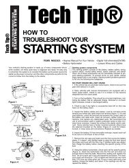
Hydraulics<br />
<strong>Hydraguide</strong><br />
<strong>Hydrostatic</strong> <strong>Steering</strong> <strong>System</strong><br />
<strong>HGB</strong> Service Manual<br />
Service Manual 2752<br />
Hydraulic Pump/Motor Division
TYPICAL OIL FLOW
Table of Contents<br />
Section I<br />
<strong>System</strong> Operation .................................................................................................................page 2<br />
Design and Function.............................................................................................................page 2<br />
Control Valve ........................................................................................................................page 3<br />
Metering Section...................................................................................................................page 3<br />
Rotor Operation ....................................................................................................................page 3<br />
Power <strong>Steering</strong> Operation ....................................................................................................page 4<br />
Manual <strong>Steering</strong> Operation...................................................................................................page 4<br />
Exploded View ......................................................................................................................page 5<br />
Service Parts List..................................................................................................................page 6<br />
Pressure Dam Check Installation .........................................................................................page 7<br />
Section II<br />
Service Procedure ................................................................................................................page 8<br />
Work Conditions ...................................................................................................................page 8<br />
Seal Replacement Instructions .............................................................................................page 8<br />
Servicing of <strong>HGB</strong> Unit...........................................................................................................page 8<br />
Disassembly Procedure........................................................................................................page 8<br />
Section III<br />
Inspection and Replacement ..............................................................................................page 11<br />
Section IV<br />
Assembly Procedure...........................................................................................................page 12<br />
Filling and Air Bleeding <strong>System</strong> ..........................................................................................page 15<br />
Hydraulic Fluid ....................................................................................................................page 15<br />
Column Assembly and Disassembly Procedures ...............................................................page 16<br />
Tips for Maintaining the <strong>System</strong> .........................................................................................page 17<br />
Exploded View ....................................................................................................................page 19<br />
!<br />
WARNING<br />
FAILURE OR IMPROPER SELECTION OF<br />
IMPROPER USE OF THE PRODUCTS<br />
AND/OR SYSTEMS DESCRIBED HEREIN<br />
OR RELATED ITEMS CAN CAUSE DEATH,<br />
PERSONAL INJURY AND PROPERTY DAM-<br />
AGE.<br />
This document and other information from Ross<br />
Operation, its subsidiaries and authorized distributors<br />
provide product and/or system options for further<br />
investigation by users having technical expertise.<br />
It is important that you analyze all aspects of<br />
your application and review the information concerning<br />
the product or system in the current product<br />
catalog. Due to the variety of operating conditions<br />
and applications for these products or systems,<br />
the user, through its own analysis is and<br />
testing, is solely responsible for making the final<br />
selection of the products and systems and assuring<br />
that all performance, safety and warning<br />
requirements of the application are met.<br />
The products described herein, including without<br />
limitation, product features, specifications, designs,<br />
availability and pricing, are subject to change by<br />
Ross Operation and its subsidiaries at any time<br />
without notice.
HYDRAGUIDE STEERING<br />
MODEL <strong>HGB</strong><br />
For over half a century, Ross has anticipated and met the changing and increasing needs for better steering of<br />
automotive, construction, industrial and agricultural machines. This hydrostatic steering system described herein<br />
is further evidence of this fact.<br />
<strong>Hydraguide</strong> is the Ross name given to hydrostatic steering systems. In the <strong>HGB</strong> type <strong>Hydraguide</strong> steering<br />
system, an engine-driven pump, relief valve, or cylinder, reservoir, filter, fluid lines, and an <strong>HGB</strong> control unit are<br />
needed. An automotive type steering wheel is attached to the <strong>HGB</strong> unit and the power cylinder is connected by<br />
suitable means to the steered wheels.<br />
The driver has power steering control at all times, so long as system components work together, system integrity<br />
is maintained, and adequate fluid is present. If there is a failure in the high-pressure circuit, a loss of power steering<br />
will result. The <strong>HGB</strong>, however, is designed to have some manual steering capability, depending on the installation.<br />
If you can’t manually steer the vehicle without using extraordinary measures, such as leaving your seat, or<br />
pushing with your legs, don’t try it. Repair the failure in the power circuit. Some vehicles may be impossible to<br />
steer manually because of their weight and size.<br />
WARNING: EXTRAORDINARY MEASURES SHOULD NOT BE USED IN ATTEMPTING TO MANUALLY<br />
STEER THE VEHICLE, AS THEY MAY GENERATE FORCES IN EXCESS OF 125 FT. LBS., THEREBY<br />
DAMAGING THE UNIT INTERNALLY, WHICH COULD RESULT IN A COMPLETE LOSS OF STEERING.<br />
WARNING: ALL STEERING MECHANISMS ARE LIFE AND LIMB ITEMS. AS SUCH, IT IS IMPERATIVE<br />
THAT THE INSTRUCTIONS IN THIS BOOKLET ARE FOLLOWED TO THE LETTER. FAILURE TO<br />
OBSERVE THE PROCEDURES SET OUT IN THIS PAMPHLET MAY RESULT IN LOSS OF STEERING.<br />
1
SECTION I<br />
A. SYSTEM OPERATION<br />
This literature with the illustrations shown covers a<br />
standard basic design of the <strong>HGB</strong> unit. Variations<br />
may be engineered to suit special requirements.<br />
The description of the operation of the <strong>HGB</strong> unit and<br />
the illustrations explain the functioning of the system<br />
for the utilization of the hydraulic power generated by<br />
the engine-driven pump for power steering.<br />
Satisfactory performance of this system requires a<br />
well engineered installation designed for the particular<br />
type of vehicle and the type and kind of<br />
service for which it will be used. Ross Engineering<br />
advice and assistance is available and we welcome<br />
requests.<br />
Information on the required engine-driven pump<br />
capacity and the power cylinder size and connecting<br />
lines are provided through engineering contacts. A<br />
balanced cylinder design is preferred.<br />
Figure <strong>HGB</strong>-1<br />
B. DESIGN & FUNCTION<br />
The <strong>HGB</strong> unit consists of a fluid control valve section<br />
and a fluid metering section which are hydraulically<br />
and mechanically inter-connected.<br />
2
C. CONTROL VALVE<br />
The control valve section contains a mechanically<br />
actuated linear spool which is torsion bar centered.<br />
The function of the control valve section is to direct<br />
the fluid to and from the metering section, to and<br />
from the cylinder, and to regulate the pressure supplied<br />
to the cylinder. The valve is provided with<br />
unique pressure chambers which insure effective circuit<br />
isolation.<br />
D. METERING SECTION<br />
The metering section consists of a commutator and<br />
bi-directional gerotor element, which contains an<br />
orbiting rotor and a fixed stator. The commutator<br />
rotates at orbit speed with the rotor and channels the<br />
fluid to and from the rotor set and the valve section.<br />
The function of the metering section is to meter the<br />
oil to the cylinder, maintaining the relationship<br />
between the hand wheel and the steered wheels.<br />
E. ROTOR OPERATION IN THE METERING<br />
ELEMENT (See Fig. <strong>HGB</strong>-3)<br />
Each lobe of the rotor has a diametrically opposite<br />
lobe, therefore, when one lobe is in a cavity its opposite<br />
lobe is at the crest of the stator’s convex form<br />
opposite the cavity. As the rotor is rotated, each lobe<br />
in sequence is moved out of its cavity to the crest of<br />
the stator’s convex form and this forces each opposite<br />
lobe, in sequence, into a cavity. Due to the interaction<br />
between the rotor and the stator, there are 42<br />
fluid discharging actions in one revolution of the<br />
rotor. When the rotor is moving, fluid is always flowing<br />
out of three of the cavities while fluid is flowing<br />
Figure <strong>HGB</strong>-2<br />
into three other cavities, and one of the cavities is<br />
inactive as it changes from one of discharging fluid to<br />
one of admitting fluid. The commutator rotates with<br />
the rotor and channels the fluid from and to the valve<br />
section, and to and from the metering element.<br />
3<br />
Figure <strong>HGB</strong>-3
F. POWER STEERING OPERATION<br />
When the spool is in center or neutral position, the<br />
hydraulic oil from the engine-driven pump circulates<br />
through the valve section, directly back to the reservoir<br />
with sufficient pressure only to overcome friction<br />
of valve channels and lines. There is no circulation of<br />
engine-driven pump oil to or from the cylinder. Note<br />
the center diagram showing neutral position<br />
(Reference the typical oil flow diagram on the back of<br />
the front cover) on which no directional arrows<br />
appear in the metering channels. The oil pressure at<br />
the two cylinder ports is equal and produces ineffective<br />
forces in the cylinder.<br />
In order to accomplish a power steering maneuver,<br />
the operator must rotate the steering wheel in the<br />
direction of the steering maneuver. The initial rotation<br />
of the steering wheel rotates the input shaft which<br />
tends to rotate the drive link and rotor set through the<br />
torsion bar centering spring. Rotation of the rotor set<br />
and spool which are coupled by the drive link, is<br />
resisted by the cylinder pressure required to overcome<br />
the steering forces. As the input shaft is rotated<br />
relative to the spool, the centering spring is torsionally<br />
deflected. Axial shift of the spool is inducted<br />
by the ball which is captive in the spool and engaged<br />
in the helical groove provided in the input shaft.<br />
When the spool is axially displaced within the body,<br />
fluid channels are selected connecting the enginedriven<br />
pump to the intake side of the rotor set via the<br />
commutator. The exhaust side of the rotor set is connected,<br />
through the commutator, to one side of the<br />
cylinder while the other side of the cylinder is connected<br />
to the reservoir. (See Figures <strong>HGB</strong>-1 and 2).<br />
Further axial displacement of the spool results in<br />
increased system pressure to provide the level of<br />
pressure required. A portion or all of the hydraulic<br />
fluid at the required pressure from the engine-driven<br />
pump, depending upon the speed of steering, is<br />
directed to the cylinder via the metering section,<br />
using cylinder movement to accomplish the steering<br />
maneuver.<br />
G. MANUAL STEERING OPERATION<br />
In the absence of system pressure, the driver's manual<br />
effort displaces the spool axially. When the spool<br />
is displaced within the body, fluid channels are<br />
selected connecting the rotor set, which is now acting<br />
as a pump, via the commutator to one side of the<br />
cylinder. The return flow from the other side of the<br />
cylinder is channeled through a recirculation valve so<br />
that the oil will flow to the intake side of the rotor set<br />
via the commutator instead of back to the reservoir.<br />
(See. Figure <strong>HGB</strong>-5) The recirculation valve is a ball<br />
check valve in a channel connecting the return flow<br />
chamber to the engine-driven pump pressure inlet<br />
chamber. The recirculation valve is closed during<br />
power operation.<br />
WARNING: EXTRAORDINARY MEASURES<br />
SHOULD NOT BE USED IN ATTEMPTING TO<br />
MANUALLY STEER THE VEHICLE, AS THEY MAY<br />
GENERATE FORCES IN EXCESS OF 125 FT.<br />
LBS., THEREBY DAMAGING THE UNIT INTER-<br />
NALLY, WHICH COULD RESULT IN A COMPLETE<br />
LOSS OF STEERING.<br />
4
USE WITH <strong>HGB</strong> SERVICE MANUAL EXPLODED VIEW<br />
1 2, 4, 5, & 6 3 7 8 9 10 11 12<br />
Wheel Seal Snap Screw Upper Seal Shim Snap Thrust<br />
Nut Kit Ring (4 ea.) Cover Kit Ring Washer<br />
026045 HG500007 401233 020206 HGA016005X1 032840X1 033157-X2 401367 400100<br />
13 14 15 16 17 Or 17 Or 17 18 19 24<br />
Thrust Thrust Wave Spacer Pin Whole Wheel Moun Full Bolt Needle Drive Ball<br />
Bearing Washer Washer Shaft Shaft Groove Shaft Roller Ring 5/16” dia.<br />
063979 400075 401366 477277 089181 089180 089193 040114 <strong>HGB</strong>013006 400013<br />
25 27 28 29 32 33 & 34 36 & 37<br />
Springs Ball Seal Wear Manifold Commutator End Cover<br />
13/16 dia. (2 ea.) Plate & Ring Assy.<br />
401412 400107 032519 477251 <strong>HGB</strong>015000 <strong>HGB</strong>014000-A1 402392-X1<br />
STANDARD PARTS THAT CHANGE WITH DISPLACEMENT<br />
20 21 & 22 30 31 35 38<br />
<strong>Series</strong> Spacer Torsion Bar* Drive Link Rotor Set Sleeve Bolts (7 ea.)<br />
<strong>HGB</strong> 16 477252-177 BASE-A1-500 <strong>HGB</strong>013001 <strong>HGB</strong>167001 099044 021400<br />
<strong>HGB</strong> 24 477252-227 BASE-A1-550 <strong>HGB</strong>013001 <strong>HGB</strong>247001 099045 021401<br />
<strong>HGB</strong> 32 477252-227 BASE-A1-600 <strong>HGB</strong>013001 <strong>HGB</strong>327001 099046 021402<br />
<strong>HGB</strong> 40 477252-327 BASE-A1-650 <strong>HGB</strong>013001 <strong>HGB</strong>407001 099043 021403<br />
<strong>HGB</strong> 48 477252-177 BASE-A1-500 <strong>HGB</strong>013002 <strong>HGB</strong>487000 099054 021404<br />
<strong>HGB</strong> 64 477252-277 BASE-A1-600 <strong>HGB</strong>013007 <strong>HGB</strong>647001 099062 021320<br />
23 & 26 Spool and housing are non-serviceable due to select fit. If either needs replaced entire hydraguide must be replaced.<br />
* Torsion bars are unit specific. To select the correct replacement, measure the diameter of the center section of the bar and the length between holes, then select<br />
the correct base number from the following chart:<br />
Base Number Bar Center Diameter - in. Length Between Holes - in.<br />
401360 0.147 5.00 - 5.62<br />
401363 0.160 6.00 - 6.50<br />
401368 0.160 5.00 - 5.62<br />
401413 0.154 5.00 - 5.62<br />
401432 0.147 6.00 - 6.50<br />
401435 0.139 5.00 - 5.62<br />
401627 0.139 6.00<br />
6
7<br />
PRESSURE DAM CHECK INSTALLATION<br />
39A<br />
39B<br />
39C<br />
39D<br />
39E<br />
39E<br />
39D<br />
39A - 036183-A1<br />
39B - 040138<br />
39C - 040113<br />
39D - 040139<br />
39E - 401411<br />
(1) PLUG & “O” RING ASSY.<br />
(2) HEX ROD<br />
(2) NEEDLE ROLLER<br />
(2) ROD<br />
(2) SPRING<br />
39B<br />
39C
SECTION II<br />
SERVICE PROCEDURE<br />
For service information on the steering pump<br />
(engine-driven) and cylinder, see information provided<br />
by the manufacturer of these units.<br />
For servicing the <strong>HGB</strong> unit and the system, see information<br />
and instructions in the following sections.<br />
Servicing of <strong>HGB</strong> Unit Page 8<br />
Filling and Air Bleeding the<br />
<strong>System</strong> When Drained of Oil Page 16<br />
Hydraulic Fluid Page 16<br />
WARNING: SINCE SOLVENTS ARE FLAMMABLE,<br />
BE EXTREMELY CAREFUL WHEN USING THEM.<br />
EVEN A SMALL EXPLOSION OR FIRE COULD<br />
CAUSE DEATH OR INJURY.<br />
SEAL REPLACEMENT INSTRUCTIONS<br />
For numerous installation you may want to purchase the<br />
J26910 tool kit available from KENT MOORE TOOL DIVI-<br />
SION, 29784 Little Mack, Roseville, Michigan 48066 -<br />
Phone 800-345-2233.<br />
Caution: Follow the Instruction and do not disassemble<br />
The <strong>Hydraguide</strong> unit upper cover (8) to replace the shaft<br />
seal (5).<br />
1. Remove the steering wheel nut (1), steering wheel<br />
and steering wheel column, if applicable. Refer to<br />
page 17 for instruction on removal of the steering column.<br />
2. Remove the dirt seal (2) over the end of the<br />
<strong>Hydraguide</strong> unit upper cover, if applicable. Discard<br />
this part.<br />
3. Remove the retaining ring (3), do not discard, this part<br />
must be reinstalled during assembly procedure.<br />
4. Remove the seal package parts (4) (5) + (6) from the<br />
<strong>Hydraguide</strong> unit by one of the following methods:<br />
a) If the <strong>Hydraguide</strong> unit has not been<br />
removed from the vehicle, rotate the<br />
<strong>Hydraguide</strong> unit input shaft either clockwise<br />
or counter clockwise to pressurize the system<br />
and force the seal package out. Discard<br />
these parts.<br />
b) If the <strong>Hydraguide</strong> unit has been removed<br />
from the vehicle plug three of the four ports<br />
in the <strong>Hydraguide</strong> unit and pressurize the<br />
other port with air pressure to force the seal<br />
package out. Discard these parts.<br />
CLEAN WORK CONDITIONS<br />
It is a must that the system be kept free of dirt or foreign<br />
matter in the oil circuit. Cleanliness in serving<br />
this power steering system is absolutely necessary.<br />
If it is necessary to disassemble any of the units,<br />
make sure that a clean work bench or table is used.<br />
(A piece of clean wrapping paper makes an excellent<br />
disposable top).<br />
Outside dirt should be cleaned off before disconnecting<br />
lines and port holes should be plugged immediately<br />
after disconnecting lines.<br />
Finish cleaning off outside dirt before placing on work<br />
bench.<br />
When disassembled, parts should be cleaned only in<br />
clear-clean petroleum base solvent and blown dry<br />
with clean, dry air. Other solvents may cause deterioration<br />
of rubber seals. Avoid wiping parts with cloth<br />
and never steam clean hydraulic steering assemblies.<br />
WARNING: EYE PROTECTION SHOULD BE<br />
WORN.<br />
WARNING: OSHA MAXIMUM AIR PRESSURE<br />
REQUIREMENTS SHOULD BE COMPLIED WITH<br />
TO PREVENT INJURY.<br />
5. Note: Clean the <strong>Hydraguide</strong> unit input shaft (17) and<br />
upper cover (8) seal bore to remove particles of dirt,<br />
felt, lint, etc. with a clean, lint-free rag. Caution:<br />
excessive particles of felt or lint can cause the new<br />
seal package to leak.<br />
6. Cover the end of the <strong>Hydraguide</strong> unit input shaft with<br />
cellophane tape to protect the new seal (5) when it is<br />
assembled over the sharp edges of the input shaft.<br />
7. Lubricate the new seal using hydraulic oil and install<br />
the new seal (5) with lip side first, onto the <strong>Hydraguide</strong><br />
unit input shaft.<br />
8. Remove the cellophane tape from the <strong>Hydraguide</strong> unit<br />
input shaft.<br />
9. Assemble the new washer (4), with small end first,<br />
onto the <strong>Hydraguide</strong> unit input shaft and push the new<br />
washer and the new seal (5), previously installed,<br />
down into the <strong>Hydraguide</strong> unit upper cover. (A short<br />
piece of metal tubing 15/16 minimum I.D. x 1-3/16<br />
maximum O.D. or a 7/8 deep well socket may be used<br />
to push these parts into place.)<br />
10. Assemble the previously used retaining ring (3) onto<br />
the <strong>Hydraguide</strong> unit input shaft and down into the<br />
<strong>Hydraguide</strong> unit upper cover groove. Be sure the<br />
rounded edge of the retaining ring (3) is faced inward.<br />
11. Assemble the new seal (2) onto the <strong>Hydraguide</strong> unit<br />
input shaft and down into the <strong>Hydraguide</strong> unit upper<br />
cover (8) counter bore.<br />
12. Assemble the steering column, if applicable.<br />
13. Assemble the steering wheel and wheel nut, torque<br />
the wheel nut to 35 ft. lbs.<br />
8
SERVICING OF <strong>HGB</strong> UNIT<br />
Refer to exploded view, Figure <strong>HGB</strong>-6 for parts identification.<br />
The valve spool (23) and the housing (26),<br />
the commutator (34), and commutator ring (33), as<br />
well as the rotor (31B) and the stator (31A) are not<br />
separately replaceable because they are selectively<br />
fitted at the factory. If the valve spool or housing<br />
need replacement, the complete housing assembly<br />
must be replaced. If the commutator or the commutator<br />
ring need replacement, both must be replaced as<br />
a matched set. If the rotor or stator need replacement,<br />
the complete rotor set (31) must be replaced.<br />
The pin in the end cover assembly (37) is not separately<br />
replaceable. If the pin or end cover need<br />
replacement, the end cover assembly (37) must be<br />
replaced.<br />
NOTE: The upper cover screws (7) and end cover<br />
screws (38) are special screws and must be<br />
replaced with the same type if they need replacement.<br />
DISSASSEMBLY PROCEDURE<br />
Plug the four port holes and clean the exterior of the<br />
unit thoroughly. Then remove the plugs.<br />
1. To prevent possible distortion or damage to unit<br />
if placed directly in vise, the following procedure<br />
should be used. Insert an “o” ring tube fitting,<br />
with tube nut or fitting cap attached, into one of<br />
the four threaded ports in the housing. Clamp<br />
the fitting in a vise in a manner which will locate<br />
the seven end cover screws (38) in an upright<br />
position. (See Figure <strong>HGB</strong>-6).<br />
2. Remove the seven end cover screws (38) from<br />
the end cover assembly (37).<br />
NOTE: Special care should be used in the<br />
following steps to insure protection of the<br />
ground and lapped faces of the components.<br />
Avoid scratching or nicking of finished<br />
surfaces.<br />
3. Remove end cover assembly (37) by inserting<br />
screw driver between end cover assembly (37)<br />
and sleeve (35). Pry up end cover assembly<br />
and lift from unit. Inspect seven end cover<br />
assembly holes for damage around edge of<br />
holes. If there is evidence of damage, replace<br />
end cover assembly. Remove and discard seal<br />
(28).<br />
CAUTION: The washer (36) and commutator<br />
(34) may adhere to the end cover assembly<br />
by oil film and may be removed with the end<br />
cover assembly. Do not attempt to remove<br />
pin in end cover because pin is press fit and<br />
is non-serviceable.<br />
4. Remove the commutator ring (33) and manifold<br />
(32) by using two of the end cover screws (38)<br />
as a lifting tool. (See Figure <strong>HGB</strong>-7). If the<br />
washer (36) and commutator (34) did not<br />
adhere to the end cover assembly, they should<br />
be lifted out with commutator ring (33) and<br />
manifold (32).<br />
Figure <strong>HGB</strong>-7<br />
5. Remove rotor set (31) and wear plate (29) by<br />
using two of the end cover screws (38) as a lifting<br />
tool. (Similar to Figure <strong>HGB</strong>-7).<br />
9<br />
Figure <strong>HGB</strong>-6
6. Remove sleeve (35) by inserting screw driver<br />
between sleeve (35) and housing (26) and pry<br />
up.<br />
7. Remove drive link (30).<br />
8. Remove seal (28) and discard.<br />
9. Remove 13/16” dia. steel ball (27). (See Figure<br />
<strong>HGB</strong>-8). Remove pressure dam components;<br />
items 39B, 39C, 39D and 39E. Refer to page 7<br />
for details.<br />
Figure <strong>HGB</strong>-9<br />
16. Remove seal (2), retaining ring (3), spacer (4),<br />
seal (5) and seal ring (6) from upper cover (8).<br />
Discard seal (2), spacer (4), Seal (5) and Seal<br />
ring (6).<br />
Figure <strong>HGB</strong>-8<br />
10. Reverse the <strong>HGB</strong> unit in the vise to place the<br />
input shaft (17) in a vertical position. Using a<br />
center punch, mark the upper cover flange (8) in<br />
relation to a similar mark placed on the port face<br />
of the housing (26) to facilitate reassembly.<br />
(See Figure <strong>HGB</strong>-9).<br />
11. Remove the four upper cover screws (7) by<br />
using a 5/16-12 point socket.<br />
12. Grasp the input shaft (17) and with a smooth<br />
upward motion, remove the input shaft (17),<br />
upper cover (8) and valve spool (23) from the<br />
housing (26).<br />
NOTE: Avoid applying side forces to the<br />
valve spool which would cause binding of<br />
the closely fitted assembly. Never use<br />
excessive force to remove the valve spool<br />
from the housing.<br />
13. Remove and discard seal (9).<br />
14. Remove the upper cover (8) with shaft seal<br />
package (items 2 thru 6) intact. Remove spacer<br />
item (16).<br />
15. Remove shims (10) from either upper cover (8)<br />
cavity or from face of thrust washer (12). Count<br />
and record the number of shims to aid in<br />
reassembly of the unit.<br />
NOTE: Retaining ring pliers should be used<br />
to remove retaining ring (3).<br />
NOTE: Seal (5) and seal ring (6) may be<br />
bonded together as a single unit.<br />
17. Remove the retaining ring (11), thrust washer<br />
(12), thrust bearing (13), thrust washer (14) and<br />
wave washer (15) from input shaft (17).<br />
18. Remove the needle roller (18) by using a pin<br />
punch of .120 max. diameter for a minimum of<br />
.625 length. The input shaft (17) should be<br />
placed on a block of wood (to avoid shaft damage)<br />
and the needle roller removed by impact<br />
using light hammer blows. (See Figure <strong>HGB</strong>-<br />
10).<br />
Figure <strong>HGB</strong>-10<br />
10
19. Remove the torsion bar (21) and spacer (20) by<br />
inverting the valve spool assembly and allowing<br />
the parts to fall free. Do not remove needle<br />
roller (22) from torsion bar. (See Figure <strong>HGB</strong>-<br />
11).<br />
Figure <strong>HGB</strong>-11<br />
20. Remove the drive ring (19) by placing the end of<br />
valve spool (23) on the surface and rotate input<br />
shaft (17) to extremes of travel until drive ring<br />
(19) falls free. (See Figure <strong>HGB</strong>-12).<br />
21. With the valve spool assembly in the same position<br />
as the step above, rotate the input shaft<br />
(17) in a clockwise direction until the 5/16” dia.<br />
steel ball (24) disengages from the helical<br />
groove in the input shaft. Lift out input shaft.<br />
CAUTION: The 5/16” dia. steel ball may fall<br />
free and care should be used to not lose it.<br />
Figure <strong>HGB</strong>-12<br />
22. Do not remove ball retaining spring (25)<br />
unless replacement is required. If necessary<br />
to remove this ball retaining spring, grasp the<br />
end with pliers and lift over the shoulder on<br />
valve spool (23). Continue with a pulling motion<br />
to progressively remove the ball retaining<br />
spring. A screw driver may be used to assist in<br />
the prying of the spring over the shoulder of the<br />
valve spool. Care must be used to avoid<br />
scratching or nicking of the valve spool outside<br />
diameter and control edges. Discard the retainer<br />
(25) if removed.<br />
This completes disassembly of the <strong>HGB</strong> unit.<br />
11
Section III<br />
INSPECTION AND REPLACEMENT<br />
Visually inspect all parts and replace those parts not<br />
in good condition. The following finished surfaces<br />
should be inspected for abnormal wear, scoring or<br />
damage.<br />
1. Housing (26) bore and ends.<br />
2. Valve spool (23) outside diameter. Some burnishing<br />
due to use may be observed.<br />
3. Valve spool (23) control edges.<br />
4. Valve spool (23) splines.<br />
5. Input shaft (17) seal area. Check for rust, pitting<br />
and excessive wear. Light circumferential polishing<br />
due to seal contact may be observed.<br />
6. Input shaft (17) helical groove. Note the contact<br />
pattern created by the actuator ball (24).<br />
Surface should be free from pits, chipping or<br />
surface break down.<br />
7. Thrust bearing (13) and thrust washers (12 and<br />
14). Inspect for pitting of rolls and faces of<br />
thrust washers.<br />
8. Drive link (30) pin slot. Width of slot must not<br />
exceed .001 inch difference at any point in its<br />
length.<br />
9. Drive link (30) teeth.<br />
10. Torsion bar (21) and needle roller (22).<br />
Difference in diameter of needle roller (22)<br />
should not exceed .001.<br />
The following parts may show a polish pattern due to<br />
the rotor action and the circular motion of the commutator.<br />
The mating surfaces of these components<br />
are ground and lapped and should be free from<br />
nicks, burrs and scoring.<br />
1. Wear Plate (29).<br />
2. Manifold (32).<br />
3. Rotor Set (31).<br />
4. Commutator (34) and commutator ring (33).<br />
Pilot Ring Tool<br />
Figure <strong>HGB</strong>-13<br />
and check for freedom of rotor rotation within<br />
the stator.<br />
Carefully lift rotor set (31) from the end cover<br />
assembly (37) and measure the thickness of<br />
the rotor (31B) and stator (31A). Thickness difference<br />
between rotor and stator shall not<br />
exceed .007 inch.<br />
Using a feeler gage, check the rotor (31B) to<br />
stator (31A) clearance as shown in figure <strong>HGB</strong>-<br />
14. If there is more than a .007 inch clearance,<br />
rotor set (31) must be replaced. (See Figure<br />
<strong>HGB</strong>-14).<br />
NOTE: If the rotor set is four inches thick,<br />
the maximum allowable clearance is .011<br />
inch.<br />
The internal splines in the rotor (31B) should<br />
not show abnormal wear or damage.<br />
Note: Thickness difference between commutator<br />
and commutator ring (33) shall not<br />
exceed .0025 inch.<br />
5. End cover assembly (37).<br />
NOTE: Rotor set (31) requires special attention<br />
in handling to avoid nicks and scratching<br />
and it is recommended that the rotor<br />
(31B), stator (31A) be checked in the assembled<br />
condition. To inspect the rotor set,<br />
place the assembly, face down, on the<br />
lapped face of the end cover assembly (37)<br />
Figure <strong>HGB</strong>-14<br />
12
SECTION IV<br />
ASSEMBLY PROCEDURE<br />
IMPORTANT: Before starting assembly, clean<br />
all parts with clean petroleum base solvent and<br />
air dry. Do not wipe dry with rags. Be sure all<br />
dried paint chips have been removed from<br />
edges of lapped surfaces. Unless otherwise<br />
indicated, do not oil parts before assembly.<br />
1. Reclamp housing (26) in the vise as shown in<br />
Figure <strong>HGB</strong>-9.<br />
2. Assemble thrust washer (14), thrust bearing<br />
(13), thrust washer (12) and retaining ring (11)<br />
(in that order) on input shaft (17).<br />
3. If the ball retaining spring (25) has been<br />
removed, install a new ball retaining spring (25)<br />
on valve spool (23). The spring must fit tightly.<br />
4. Insert 5/16” dia. steel ball (24) into ball seat<br />
located inside valve spool. (23).<br />
5. Assemble wave washer (15) over thrust washer<br />
(14) and thrust bearing (13). Insert the input<br />
shaft (17) into the valve spool engaging the<br />
helix and 5/16” dia. steel ball with counterclockwise<br />
motion. This operation is best done while<br />
holding the spool in a horizontal position.<br />
6. Using the midsection of the torsion bar (21) as<br />
a gage, insert the gage between the valve<br />
spool end and the thrust washer (14). (See<br />
Figure <strong>HGB</strong>-15). This will position the spool in<br />
the necessary radial relationship with the input<br />
shaft spline teeth for the assembly of the drive<br />
ring (19).<br />
Figure <strong>HGB</strong>-15<br />
Figure <strong>HGB</strong>-15A<br />
of the input shaft will allow the drive ring to<br />
become fully engaged. Remove the torsion bar<br />
(21) gage. (See Figure <strong>HGB</strong>-15A).<br />
NOTE: Rotate the input shaft (17) out of the<br />
valve spool (23) until input shaft will no<br />
longer rotate. There will be a gap of approximately<br />
.350 between end of valve spool (23)<br />
and thrust washer (14) if the drive ring (19)<br />
is assembled properly.<br />
CAUTION: The <strong>HGB</strong> will not operate properly<br />
if the correct orientation of spool, drive<br />
ring, and input shaft is not obtained.<br />
9. Install spacer (20) over torsion bar (21) and<br />
insert the torsion bar into the valve spool (23).<br />
10. Align the cross-hole in the torsion bar (21) with<br />
the cross-hole in the input shaft (17) and insert<br />
a .120 diameter pin punch to maintain alignment.<br />
11. Insert needle roller (18) into cross-hole in input<br />
shaft (17) and while retracting the pin punch,<br />
engage the needle roller in the torsion bar (21)<br />
cross-hole.<br />
12. Initiate press of needle roller (18) into torsion<br />
bar (21) with a few light impacts. Press needle<br />
roller flush with outside diameter of input shaft<br />
(17) using a 1/2” drive socket of 11/16” size for<br />
supporting the input shaft. (See Figure <strong>HGB</strong>-<br />
16). With a few light impacts on .120 diameter<br />
pin punch, drive needle roller (18) approximately<br />
1/32 below the input shaft (17) outside diameter.<br />
(See <strong>HGB</strong>-10).<br />
7. Place the input shaft (17) and valve spool (23)<br />
assembly in a vertical position with the input<br />
shaft end on the table surface.<br />
13<br />
8. Insert the drive ring (19) into the valve spool<br />
(23) end by visually aligning an internal space<br />
on the drive ring with a tooth on the input shaft<br />
(17) spline and allow drive ring to drop to the<br />
limit of its travel. If the drive ring does not<br />
engage the input shaft spline, a slight rotation<br />
Figure <strong>HGB</strong>-16
13a. Assemble spacer (16) over valve spool end of<br />
input shaft and valve spool assembly. If spacer<br />
(16) has an inside lip on one end, the inside lip<br />
end must be against the wave washer (15)<br />
when spacer (16) is assembled.<br />
13b. Place assembly, spool end first, into housing<br />
(26).<br />
NOTE: Avoid applying side forces to the<br />
valve spool which could cause binding of<br />
the closely fitted assembly.<br />
NOTE: If neither the input shaft (17) or<br />
upper cover (8) are replaced the original<br />
shims (10) may be reused. However, if in<br />
the inspection of parts, damage is found to<br />
the shims, discard these shims and replace<br />
with new parts of equal thickness.<br />
14a. Place shims on top of the thrust washer (12).<br />
Coat seal (9) with clean grease and place in<br />
upper cover (8) counter-bore. Assemble upper<br />
cover onto input shaft (17) and rotate to align<br />
punch marks previously made during disassembly.<br />
spool, torsion bar or upper cover (8) have<br />
been replaced, the following procedure for<br />
checking and shim adjustment must be<br />
used.<br />
14b. Re-assemble as in “14a” above using the<br />
required new parts. After torquing the four<br />
upper cover screws (7), revolve unit in vise so<br />
that the input shaft is pointing downward. In<br />
order to determine that the unit is shimmed<br />
correctly, the drive link (30) must be in its proper<br />
position. To do this, grasp the input shaft<br />
(17), pull downward, to prevent rotation.<br />
Engage drive link splines in valve spool (23)<br />
and rotate to position valve spool essentially<br />
flush with end of housing (26). Remove drive<br />
link (30) and orient drive link slot to engage<br />
needle roller (22) and insert drive link (30).<br />
Observe relationship of valve spool (23) end to<br />
housing (26) step. If this is within .0025 of<br />
being flush, no additional shimming is required.<br />
(See Figure <strong>HGB</strong>-19). If not within .0025, add<br />
or remove shims (10) until this requirement is<br />
satisfied repeating assembly steps as outlined<br />
in “14a” above. (See Figure <strong>HGB</strong>-19).<br />
Figure <strong>HGB</strong>-18<br />
Figure <strong>HGB</strong>-17<br />
NOTE: If a new upper cover (8) is used, no<br />
angular orientation is required. However, it<br />
is necessary to align the upper cover (8)<br />
and housing (26) if both parts are reused.<br />
Replace upper cover screws (7) finger tight.<br />
Assemble pilot ring tool (See Figure <strong>HGB</strong>-13,<br />
page 12) over upper cover (8) (See Figures<br />
<strong>HGB</strong>-17 and <strong>HGB</strong>-18). Assemble worm drive<br />
type hose clamp over pilot ring tool and pilot on<br />
housing (26) (See Figures <strong>HGB</strong>-17 and <strong>HGB</strong>-<br />
18). Tighten hose clamp to align upper cover<br />
with housing. Now torque the four upper cover<br />
screws (7) to 18-22 ft. lbs.<br />
NOTE: If the input shaft (17), housing and<br />
14c. The correct shimming must be checked on the<br />
vehicle or on a suitable hydraulic test stand.<br />
The amount of steering effort required to steer<br />
the vehicle when the vehicle is at rest on dry<br />
pavement must be equal within two inch<br />
pounds. For example: if fifteen inch pounds is<br />
required to steer to the right, not less than thirteen<br />
or more than seventeen inch pounds<br />
should be required to steer to the left.<br />
If a test stand is available to place a load<br />
between cylinder ports in the same manner as<br />
on the vehicle, a test stand may be used. Add<br />
shims to increase steering efforts in a left<br />
turn, subtract shims to increase steering<br />
effort in a right turn.<br />
15. With drive link (30) installed as described<br />
above, install new seal (28). Install 13/16” dia.<br />
14
must be assembled with the countersink<br />
side against the washer (36).<br />
22. Position the end cover assembly (37) with commutator<br />
(34), washer (36) and seal (28) in place<br />
as shown in Figure <strong>HGB</strong>-21.<br />
NOTE: The relationship of the small elongated<br />
hole in the commutator (34) to one of the<br />
seven holes in the end cover assembly (37)<br />
and one of the assembly posts is very<br />
important. They must be “in line” as shown<br />
in Figure <strong>HGB</strong>-21.<br />
23. Turn the input shaft (17) to locate the tip of the<br />
drive link (30) in a position so that it will accept<br />
the elongated hole in the commutator (34).<br />
Figure <strong>HGB</strong>-19<br />
steel ball (27) into housing. (See Figure <strong>HGB</strong>-<br />
8).<br />
16. Screw the two assembly posts into the housing<br />
as shown in Figure <strong>HGB</strong>-20. These assembly<br />
posts can be made by simply cutting the heads<br />
off of two screws similar to the end cover<br />
screws (38).<br />
17. Install wear plate (29), rotor set (31), manifold<br />
(32) and commutator ring (33) over the assembly<br />
posts. (See Figure <strong>HGB</strong>-20). NOTE: The<br />
rotor spines are positioned toward the commutator<br />
end.<br />
18. Apply a small amount of clean grease to the<br />
inside of each end of sleeve (35) and to the<br />
exposed area of seal (28) previously assembled<br />
on housing (26).<br />
Assemble the sleeve (35) over the <strong>HGB</strong> unit<br />
and place it on top of seal (28) and housing (26)<br />
in a non-cocked position. Assemble end cover<br />
assembly (37) onto sleeve (35). Assemble five<br />
of the end cover screws (38) into the <strong>HGB</strong> unit<br />
finger tight. Alternately and progressively, snug<br />
up the end cover screws to draw the sleeve<br />
down into its proper position over seal (28).<br />
Remove five end cover screws (38). Remove<br />
end cover assembly (37).<br />
19. Assemble new seal (28) on small diameter of<br />
end cover assembly (37).<br />
20. Apply a small amount of clean grease to the<br />
washer (36) and install it over the pin in the end<br />
cover assembly (37). The grease should<br />
adhere the washer to the end cover assembly.<br />
21. Apply a small amount of clean grease to commutator<br />
(34) and install it over the pin in the end<br />
cover assembly (37) and on top of washer (36).<br />
The grease should adhere the commutator to<br />
the end cover assembly. The commutator (34)<br />
15<br />
Figure <strong>HGB</strong>-20<br />
Figure <strong>HGB</strong>-21
24. Apply a generous amount of clean grease to<br />
seal (28) assembled previously on end cover<br />
assembly (37). Carefully turn the end cover<br />
assembly (37) over and onto the assembly<br />
posts. Place the end cover assembly on top of<br />
the sleeve in a non-cocked position. Do Not<br />
Attempt to press end cover assembly down<br />
into place.<br />
25. Install five end cover screws (38) finger tight.<br />
Remove the two assembly posts and install<br />
other two end cover screws (38) finger tight.<br />
Alternately and progressively, snug up end<br />
cover assembly down into place. Finish tightening<br />
end cover screws to 45-55 ft. lbs. torque.<br />
NOTE: Rotate the input shaft during final<br />
torque procedure to prevent binding.<br />
26. Relocate <strong>HGB</strong> Unit in vise with input shaft (17)<br />
up and install new seal ring (6) onto input shaft.<br />
27. Note: Cover the end of the <strong>Hydraguide</strong> unit<br />
input shaft with cellophane tape to protect the<br />
new seal (5) when it is assembled over the<br />
sharp edges of the input shaft.<br />
Lubricate the new seal using hydraulic oil and<br />
install the new seal (5) with lip side first, on to<br />
the <strong>Hydraguide</strong> unit input shaft (17).<br />
NOTE: Seal (5) and seal ring (6) may be<br />
bonded together as a single unit. Lubricate<br />
and install new seal with lip side first onto<br />
input shaft.<br />
28. Assemble new spacer (4) with small end first,<br />
onto input shaft (17) and push new spacer (4),<br />
new seal ring (6) and new seal (5), previously<br />
installed, down into upper cover (8) seal bore.<br />
(A short piece of metal tubing, 15/16 minimum<br />
I.D. x 1-3/16 maximum O.D. or a 7/8 deep well<br />
socket may be used to push these parts into<br />
place.<br />
29. Assemble retaining ring (3) onto input shaft (17)<br />
and down into upper cover (8) groove. Be sure<br />
the rounded edge of the retaining ring (3) is<br />
faced inward.<br />
30. Assemble new seal (2) onto input shaft (17) and<br />
down into upper cover (8) counterbore.<br />
NOTE: if the unit is to be stored, plug the<br />
cylinder ports and fill the inlet port with<br />
clean oil. Rotate input shaft until oil appears<br />
at port.<br />
31. Replug the port holes to prevent entrance of<br />
dirt. This completes assembly of the <strong>HGB</strong> unit.<br />
FILLING AIR BLEEDING THE SYSTEM<br />
WHEN DRAINED OF OIL<br />
1. Fill reservoir nearly full. Be ready to add oil<br />
when the engine is started. Do not let oil level<br />
drop below the inlet to the power pump so that<br />
the power pump will not suck air into the system.<br />
2. Start engine and let it idle. Immediately add oil<br />
to the reservoir as needed.<br />
NOTE: This oil will now be circulating only<br />
from the power pump to and through part of<br />
the <strong>HGB</strong> control valve and to the reservoir<br />
and back to the power pump.<br />
When no more oil can be added and oil is clear,<br />
proceed as follows.<br />
3. With one finger on a spoke of the steering<br />
wheel, spin wheel as rapidly as possible to<br />
bleed the air in the steering cylinder(s) and<br />
lines.<br />
4. Immediately upon <strong>HGB</strong> valve spool actuation oil<br />
must be added to the reservoir — to replenish<br />
the oil moving into the circuit.<br />
5. Keep rotating the steering wheel to keep the<br />
<strong>HGB</strong> valve spool actuated. Do this until the road<br />
wheels have reached the stop in that direction,<br />
then quickly reverse the steering wheel rotation<br />
to actuate the <strong>HGB</strong> valve spool in the opposite<br />
direction.<br />
6. Keep rotating the steering wheel left and right<br />
from stop to stop of the road wheels to bleed<br />
out air. Replenish oil as necessary.<br />
7. The air will bleed out only at the reservoir,<br />
therefore, the oil must be circulated in both<br />
directions repeatedly until the air has bled out.<br />
NOTE: The oil in the lines to the power<br />
cylinder reaches a “dead end” at the piston.<br />
The oil in the cylinder does not flow in a circuit.<br />
As the piston moves back and forth the<br />
oil moves back and forth in the lines.<br />
Therefore, air in these lines and the cylinder<br />
may be slow moving into the <strong>HGB</strong> control<br />
valve and to the reservoir.<br />
CAUTION: Do not operate vehicle until air is<br />
bled out.<br />
8. When the oil in the reservoir is clear (not cloudy<br />
or creamy), the system is free of air. (Slight<br />
creep or drift of the steering wheel is normal.)<br />
9. Adjust the oil to recommended level in reservoir<br />
and assemble reservoir cover.<br />
10. Always fill reservoir to recommended level.<br />
HYDRAULIC FLUID<br />
Keep the steering system filled with one of the<br />
following:<br />
Automatic Transmission Fluid Type “F”<br />
Automatic Transmission Fluid Dexron II<br />
Hydraulic fluid as recommended by the vehicle<br />
manufacturer.<br />
WARNING: DO NOT MIX OIL TYPES, ANY MIX-<br />
TURE, OR AN UNAPPROVED OIL, COULD<br />
DETERIORATE THE SEALS. ENOUGH FLUID<br />
COULD THEN LEAK TO CREATE A LOSS OF<br />
POWER STEERING ASSIST. DO NOT ALLOW<br />
FLUID LEVEL TO GO BELOW FILL LINE ON<br />
DIPSTICK. BEFORE ADDING NEW FLUID,<br />
COMPLETELY DRAIN OLD OIL FROM THE<br />
SYSTEM. IT MAY BE NECESSARY ALSO THAT<br />
YOU FLUSH THE SYSTEM WITH CLEAN OIL.<br />
16
<strong>HGB</strong> COLUMN<br />
1. 475109-A1<br />
2. 403813<br />
3. 401362<br />
4. 040050<br />
5. 089142<br />
6. 096245<br />
7. 063980<br />
8. 026045<br />
6. & 7. 096245-A1<br />
17<br />
TO DISASSEMBLE COLUMN<br />
1. Remove steering wheel and wheel nut (8).<br />
2. Loosen clamp assembly (1) on upper cover of<br />
<strong>HGB</strong> unit. If the application has a column support<br />
clamp, this clamp should be loosened at<br />
this time.<br />
3. If there is a horn contact assembly on the column,<br />
remove the 4 small screws from the metal<br />
cover (if applicable), and remove the metal<br />
cover and gasket. Remove the 2 small screws<br />
from the horn contact assembly.<br />
4. Pull the jacket tube (6) and bearing assembly<br />
(7) off of the wheel tube (5).<br />
5. Remove the retaining springs (3).<br />
6. Lightly tap out the pins (4) with brass rods and<br />
hammer. Do not hit the pins with heavy hammer<br />
blows, as this may damage the needle<br />
bearing in the <strong>HGB</strong> unit.<br />
7. Remove the wheel tube (5).<br />
8. Remove the coupling (2).<br />
9. Remove the clamp assembly (1).<br />
TO ASSEMBLE COLUMN<br />
1. Assemble the clamp assembly (1) onto the <strong>HGB</strong><br />
unit. (Do not tighten.)<br />
2. Assemble the coupling (2) and align pin hole.<br />
3. Assemble one of the pins (4) and one of the<br />
retaining rings (3).<br />
4. Assemble the wheel tube (5) and align pin hole.<br />
5. Assemble the other pin (4) and retaining ring (3).<br />
6. Apply a small amount of clean grease to the<br />
inside of bearing assembly (7).<br />
7. Assemble the jacket tube (6) and bearing<br />
assembly (7) over the wheel tube, through the<br />
clamp assembly (1) and onto the <strong>HGB</strong> unit<br />
upper cover.<br />
8. Tighten the clamp assembly (1) bolt to 15-20 ft.<br />
lbs.<br />
9. Assemble the steering wheel and tighten the<br />
wheel nut to 32.5 - 37.5 ft. lbs.<br />
10. If the application has a column support clamp, it<br />
is extremely important that the jacket tube (6)<br />
align with this clamp in the free state. If misalignment<br />
is evident, the <strong>HGB</strong> unit must be shimmed<br />
at the mounting surface to eliminate the misalignment,<br />
or damage may result to the <strong>HGB</strong><br />
unit.<br />
11. If applicable, assemble the horn contact assembly,<br />
cover gasket and metal cover on the jacket<br />
tube (6).
TIPS FPR MAINTAINING THE HYDRO-<br />
STATIC STEERING SYSTEM<br />
— Top up fluid level in reservoir as necessary.<br />
— Maintain correctly inflated tires.<br />
— Always use a puller to remove the steering<br />
wheel. Do not use a hammer, torch, or crow bar.<br />
— Investigate and correct immediately any play,<br />
rattle, shimmy, or other unusual occurrence in<br />
the steering system.<br />
— Remove cause of steering column misalignment.<br />
— Encourage all drivers or operators to report any<br />
malfunction or accident that may have damaged<br />
a steering system part.<br />
component. Replace the component with original<br />
equipment only.<br />
— Do not cold straighten, hot straighten, or bend<br />
any steering part.<br />
— Prevent dirt or other foreign matter from entering<br />
the hydraulic system. Clean off around filler<br />
caps before checking oil level.<br />
— Investigate and correct any external leak in the<br />
steering system, no matter how minor the leak.<br />
— Comply with manufacturer’s specifications for<br />
cleaning or replacing the filter.<br />
WARNINGS for Proper <strong>Steering</strong><br />
<strong>System</strong> Operation<br />
— Do not attempt to weld any broken steering<br />
WARNING:DO NOT WELD, BRAZE, OR SOL-<br />
DER ANY STEERING SYSTEM COMPONENT.<br />
WARNING: MAXIMUM OPERATING PRESSURE<br />
MUST NOT EXCEED VEHICLE MANUFACTUR-<br />
ER’S RECOMMENDED PUMP PRESSURE<br />
CAPACITY.<br />
WARNING: ALWAYS CAREFULLY INSPECT<br />
ANY STEERING SYSTEM COMPONENT THAT<br />
MAY HAVE BEEN STRUCK OR DAMAGED DUR-<br />
ING OPERATION OR IN AN ACCIDENT.<br />
REPLACE ANY COMPONENT THAT IS DAM-<br />
AGED OR THAT IS QUESTIONABLE.<br />
Ross extends close technical cooperation and assistance. If steering problems occur which you cannot<br />
solve, please contact our Ross Field Service Department. Our phone number and address are on the<br />
back cover of this manual.<br />
18
OIL FLOW (From Recirculating Valve)<br />
RETURN OIL (To Recirculating Valve)<br />
METERED OIL FLOW (To Cylinder)
<strong>HGB</strong> Service Manual<br />
Ross Operation<br />
2745 Snapps Ferry Road<br />
Greeneville, TN 37745 USA<br />
Tel: (423) 639-8151<br />
Fax: (423) 787-2418 (Sales)<br />
2500/1-96 BB