Sooner Trailers Owners Manual - Pirate4x4.Com
Sooner Trailers Owners Manual - Pirate4x4.Com
Sooner Trailers Owners Manual - Pirate4x4.Com

Create successful ePaper yourself
Turn your PDF publications into a flip-book with our unique Google optimized e-Paper software.
<strong>Sooner</strong> Trailer User’s <strong>Manual</strong><br />
<strong>Sooner</strong> Trailer Manufacturing Co.<br />
1515 McCurdy<br />
Duncan, OK 73533<br />
(800) 256-6668<br />
Fax (580) 255-9783<br />
<strong>Sooner</strong> <strong>Trailers</strong><br />
I
<strong>Sooner</strong> Trailer Manufacturing Co.<br />
SOONER TRAILERS<br />
THIS OPERATING MANUAL CONTAINS SAFETY<br />
INFORMATION AND INSTRUCTIONS FOR YOUR TRAILER.<br />
YOU MUST READ THIS MANUAL BEFORE LOADING OR<br />
TOWING YOUR TRAILER.<br />
YOU MUST FOLLOW ALL SAFETY PRECAUTIONS AND<br />
INSTRUCTIONS.<br />
<strong>Sooner</strong> Trailer Manufacturing Co.<br />
1515 McCurdy<br />
Duncan, OK 73533<br />
(800) 256-6668 Phone<br />
(580) 255-9783 Facsimile<br />
III
Table of Contents<br />
SOONER TRAILERS<br />
1. SAFETY INFORMATION . . . . . . . . . . . . . . . . . . . . . . . . . . . . . . . . . . . . . . . . . . . . . 3<br />
1.A. Safety Alert Symbols and Signal Words . . . . . . . . . . . . . . . . . . . . . . . . . . . 3<br />
1.B. Major Hazards . . . . . . . . . . . . . . . . . . . . . . . . . . . . . . . . . . . . . . . . . . . . . . . 4<br />
1.B.1. Driving Too Fast. . . . . . . . . . . . . . . . . . . . . . . . . . . . . . . . . . . . . . . . . . 4<br />
1.B.2. Failure to Adjust Handling While Towing a Trailer . . . . . . . . . . . . . . . . 5<br />
1.B.3. Trailer Not Properly Coupled to the Hitch . . . . . . . . . . . . . . . . . . . . . . 6<br />
1.B.4. Incorrect Use of Safety Chains . . . . . . . . . . . . . . . . . . . . . . . . . . . . . . 6<br />
1.B.5. Incorrect Use of Breakaway Brake . . . . . . . . . . . . . . . . . . . . . . . . . . . 7<br />
1.B.6. Mismatch of Trailer and Hitch . . . . . . . . . . . . . . . . . . . . . . . . . . . . . . . 8<br />
1.B.7. Unsafe Tires, Lug Nuts or Wheels. . . . . . . . . . . . . . . . . . . . . . . . . . . . 8<br />
1.B.8. Overload . . . . . . . . . . . . . . . . . . . . . . . . . . . . . . . . . . . . . . . . . . . . . . 10<br />
1.B.9. Unsafe Load Distribution . . . . . . . . . . . . . . . . . . . . . . . . . . . . . . . . . . . 11<br />
1.B.10. Shifting Cargo . . . . . . . . . . . . . . . . . . . . . . . . . . . . . . . . . . . . . . . . . 12<br />
1.B.11. Inappropriate Cargo . . . . . . . . . . . . . . . . . . . . . . . . . . . . . . . . . . . . . 13<br />
1.B.12. Inoperable Brakes, Lights or Mirrors . . . . . . . . . . . . . . . . . . . . . . . . 14<br />
1.B.13. Hazards From Modifying Your Trailer . . . . . . . . . . . . . . . . . . . . . . . 14<br />
1.B.14. Hazards to Horses (Horse Trailer). . . . . . . . . . . . . . . . . . . . . . . . . . 15<br />
1.B.15. Hazards to Livestock (Livestock Trailer) . . . . . . . . . . . . . . . . . . . . . 16<br />
1.B.16. Hazards from Accessories . . . . . . . . . . . . . . . . . . . . . . . . . . . . . . . . 17<br />
1.B.17. Reporting Safety Defects. . . . . . . . . . . . . . . . . . . . . . . . . . . . . . . . . 21<br />
1.B.18. Safety Warning Labels on Your Trailer . . . . . . . . . . . . . . . . . . . . . . 22<br />
1.B.19. Trailer Towing Guide . . . . . . . . . . . . . . . . . . . . . . . . . . . . . . . . . . . . 26<br />
2. COUPLING TO THE TOW VEHICLE . . . . . . . . . . . . . . . . . . . . . . . . . . . . . . . . . . . 29<br />
2.A. Use an Adequate Tow Vehicle and Hitch . . . . . . . . . . . . . . . . . . . . . . . . . 29<br />
2.A.1. Trailer Information . . . . . . . . . . . . . . . . . . . . . . . . . . . . . . . . . . . . . . . 30<br />
2.A.2. Tow Vehicle . . . . . . . . . . . . . . . . . . . . . . . . . . . . . . . . . . . . . . . . . . . . 32<br />
2.B. Coupling and Uncoupling the Trailer . . . . . . . . . . . . . . . . . . . . . . . . . . . . . 34<br />
2.B.1. Trailer with Ball-Hitch Coupler . . . . . . . . . . . . . . . . . . . . . . . . . . . . . . 36<br />
2.B.2. Couple the trailer to the tow vehicle . . . . . . . . . . . . . . . . . . . . . . . . . 39<br />
2.B.3. Rig the safety chains . . . . . . . . . . . . . . . . . . . . . . . . . . . . . . . . . . . . . 40<br />
2.B.4. Attach and test electric breakaway brake system . . . . . . . . . . . . . . . 41<br />
2.B.5. Connect the electrical cables. . . . . . . . . . . . . . . . . . . . . . . . . . . . . . . 43<br />
2.B.6. Uncoupling the Ball Hitch Trailer with Tongue Jack. . . . . . . . . . . . . . 44<br />
2.B.7. Trailer with Gooseneck Coupler and Drop-leg Jack . . . . . . . . . . . . . 45<br />
2.B.8. Prepare the ball receiver and gooseneck ball . . . . . . . . . . . . . . . . . . 51<br />
2.B.9. Couple the trailer to the tow vehicle . . . . . . . . . . . . . . . . . . . . . . . . . 52<br />
2.B.10. Rig the safety chains . . . . . . . . . . . . . . . . . . . . . . . . . . . . . . . . . . . . 55<br />
2.B.11. Attach and test the breakaway brake system . . . . . . . . . . . . . . . . . 56<br />
2.B.12. Connect the electrical cables. . . . . . . . . . . . . . . . . . . . . . . . . . . . . . 58<br />
2.B.13. Uncoupling the Gooseneck Trailer with Drop-leg Jack . . . . . . . . . . 58<br />
1
Table of Contents<br />
SOONER TRAILERS<br />
3. LOADING THE TRAILER . . . . . . . . . . . . . . . . . . . . . . . . . . . . . . . . . . . . . . . . . . . 63<br />
3.A. Checking Tongue Weight. . . . . . . . . . . . . . . . . . . . . . . . . . . . . . . . . . . . . . 65<br />
3.B. Securing the Cargo . . . . . . . . . . . . . . . . . . . . . . . . . . . . . . . . . . . . . . . . . . 65<br />
3.B.1. Loading Cargo (Enclosed Trailer) . . . . . . . . . . . . . . . . . . . . . . . . . . . 65<br />
3.B.2. Loading Horses (Horse Trailer) . . . . . . . . . . . . . . . . . . . . . . . . . . . . . 69<br />
3.B.3. Loading Livestock (Livestock Trailer) . . . . . . . . . . . . . . . . . . . . . . . . 75<br />
4. Checking the Trailer Before and During Each Tow . . . . . . . . . . . . . . . . . . . 78<br />
4.A. Pre-tow Checklist . . . . . . . . . . . . . . . . . . . . . . . . . . . . . . . . . . . . . . . . . . . 78<br />
4.B. Make Regular Stops . . . . . . . . . . . . . . . . . . . . . . . . . . . . . . . . . . . . . . . . . 78<br />
5. Breaking-in a New Trailer . . . . . . . . . . . . . . . . . . . . . . . . . . . . . . . . . . . . . . . . 79<br />
5.A. Retighten Lug Nuts at First 10, 25 & 50 Miles . . . . . . . . . . . . . . . . . . . . . 79<br />
5.B. Adjust Brake Shoes at First 200 Miles . . . . . . . . . . . . . . . . . . . . . . . . . . . 79<br />
5.C. Synchronizing the Brake Systems . . . . . . . . . . . . . . . . . . . . . . . . . . . . . . 80<br />
6. Accessories . . . . . . . . . . . . . . . . . . . . . . . . . . . . . . . . . . . . . . . . . . . . . . . . . . . 81<br />
6.A. Gasoline-powered Electric Generators . . . . . . . . . . . . . . . . . . . . . . . . . . . 81<br />
6.B. Accessory Battery . . . . . . . . . . . . . . . . . . . . . . . . . . . . . . . . . . . . . . . . . . . 82<br />
6.C. Shore Power . . . . . . . . . . . . . . . . . . . . . . . . . . . . . . . . . . . . . . . . . . . . . . . 83<br />
6.D. LP Gas Fuel System . . . . . . . . . . . . . . . . . . . . . . . . . . . . . . . . . . . . . . . . . 84<br />
6.D.1. LP Gas System Troubleshooting. . . . . . . . . . . . . . . . . . . . . . . . . . . . 86<br />
6.E. Vending & Accessory Doors . . . . . . . . . . . . . . . . . . . . . . . . . . . . . . . . . . . 87<br />
6.F. Electric-powered Jack(s) . . . . . . . . . . . . . . . . . . . . . . . . . . . . . . . . . . . . . . 87<br />
7. Inspection Service & Maintenance . . . . . . . . . . . . . . . . . . . . . . . . . . . . . . . . 89<br />
7.A. Inspection, Service & Maintenance Summary Charts. . . . . . . . . . . . . . . . 89<br />
7.B. Inspection and Service Instructions . . . . . . . . . . . . . . . . . . . . . . . . . . . . . 92<br />
7.B.1. Axle Bolts, Frame, Suspension, & Structure . . . . . . . . . . . . . . . . . . . 92<br />
7.B.2. Trailer Cleaning . . . . . . . . . . . . . . . . . . . . . . . . . . . . . . . . . . . . . . . . . 93<br />
7.B.3. Drop Ramp Torsion Springs. . . . . . . . . . . . . . . . . . . . . . . . . . . . . . . . 96<br />
7.B.4. Slide-Outs . . . . . . . . . . . . . . . . . . . . . . . . . . . . . . . . . . . . . . . . . . . . . 96<br />
7.B.5. Trailer Brakes. . . . . . . . . . . . . . . . . . . . . . . . . . . . . . . . . . . . . . . . . . . 97<br />
7.B.6. Trailer Connection to Tow Vehicle . . . . . . . . . . . . . . . . . . . . . . . . . . 100<br />
7.B.7. Landing Leg or Jack . . . . . . . . . . . . . . . . . . . . . . . . . . . . . . . . . . . . 102<br />
7.B.8. Lights and Signals . . . . . . . . . . . . . . . . . . . . . . . . . . . . . . . . . . . . . . 102<br />
7.B.9. Accessory Battery . . . . . . . . . . . . . . . . . . . . . . . . . . . . . . . . . . . . . . 102<br />
7.B.10. Tires . . . . . . . . . . . . . . . . . . . . . . . . . . . . . . . . . . . . . . . . . . . . . . . . 103<br />
7.B.11. Wheel Rims . . . . . . . . . . . . . . . . . . . . . . . . . . . . . . . . . . . . . . . . . . 103<br />
7.B.12. Wheels, Bearings and Lug Nuts . . . . . . . . . . . . . . . . . . . . . . . . . . 103<br />
7.B.13. Lug Nuts (Bolts) . . . . . . . . . . . . . . . . . . . . . . . . . . . . . . . . . . . . . . . 107<br />
2
1. Safety Information<br />
Safety Information<br />
1.A. Safety Alert Symbols and Signal Words<br />
Loss of control of the trailer or trailer/tow vehicle combination can result in<br />
death or serious injury. The most common causes for loss of control of the<br />
trailer are:<br />
Driving too fast for the conditions (maximum speed when towing a trailer<br />
is 60 m.p.h.); Overloading the trailer or loading the trailer unevenly; Trailer<br />
improperly coupled to the hitch; Inadequate tow vehicle or towing hitch;<br />
No braking on trailer; Not maintaining proper tire pressure; Not keeping lug<br />
nuts tight; and Not properly maintaining the trailer structure.<br />
An operating manual that provides general trailer information cannot<br />
cover all of the specific details necessary for the proper combination of<br />
every trailer, tow vehicle and hitch. Therefore, you must read, understand<br />
and follow the instructions given by the tow vehicle and trailer hitch<br />
manufacturers, as well as the instructions in this manual.<br />
Trailer Components<br />
Our trailers are built with components produced by various manufacturers.<br />
Some of these items have separate instruction manuals. Where this<br />
manual indicates that you should read another manual, and you do not<br />
have that manual, call <strong>Sooner</strong> Trailer Manufacturing Co. at (800) 256-6668<br />
for a free copy.<br />
The safety information in this manual is denoted by the safety alert symbol:<br />
The level of risk is indicated by the following signal words.<br />
DANGER- IMMEDIATE HAZARDS WHICH WILL RESULT<br />
IN SEVER PERSONAL INJURY OR DEATH IF THE<br />
WARNING IS IGNORED.<br />
3
Safety Information<br />
<strong>Sooner</strong> <strong>Trailers</strong><br />
WARNING- HAZARDS OR UNSAFE PRACTICES WHICH<br />
COULD RESULT IN SEVER PERSONAL INJURY OR<br />
DEATH IF THE WARNING IS IGNORED.<br />
CAUTION - HAZARDS OR UNSAFE PRACTICES WHICH<br />
COULD RESULT IN MINOR OR MODERATE INJURY IF<br />
THE WARNING IS IGNORED.<br />
NOTICE - PRACTICES THAT COULD RESULT IN<br />
DAMAGE TO THE TRAILER OR OTHER PROPERTY.<br />
1.B. Major Hazards<br />
1.B.1. Driving Too Fast<br />
With ideal road conditions, the maximum speed when safely towing a trailer<br />
is 60 m.p.h. If you drive too fast, the trailer tires will overheat and possibly<br />
blowout. As your speed increases, you are more likely to suddenly lose<br />
control. Never exceed 60 m.p.h. while towing the trailer.<br />
DRIVING TOO FAST FOR CONDITIONS CAN RESULT IN<br />
LOSS OF CONTROL AND CAUSE DEATH OR SERIOUS<br />
INJURY.<br />
DECREASE YOUR SPEED AS ROAD, WEATHER AND<br />
LIGHTING CONDITIONS DETERIORATE.<br />
4
Safety Information<br />
<strong>Sooner</strong> <strong>Trailers</strong><br />
1.B.2. Failure to Adjust Handling While Towing a Trailer<br />
When towing a trailer, you will have decreased acceleration, increased<br />
stopping distance, and increased turning radius (which means you must<br />
make wider turns to keep from hitting curbs, vehicles, and anything else<br />
that is on the inside corner). In addition, you will need a longer distance to<br />
pass, due to slower acceleration and increased length.<br />
Be alert for slippery conditions. You are more likely to be affected by<br />
slippery road surfaces when driving a tow vehicle with a trailer, than driving<br />
a tow vehicle without a trailer.<br />
Anticipate the trailer “swaying.” Swaying is the trailer reaction to the air<br />
pressure wave caused by passing trucks and busses. Continued pulling<br />
of the trailer provides a stabilizing force to correct swaying. Do not apply<br />
the brakes to correct trailer swaying. Check rearview mirrors frequently to<br />
observe the trailer and traffic. Use lower gear when driving down steep or<br />
long grades. Use the engine and transmission as a brake. Do not ride the<br />
brakes, as they can overheat and become ineffective.<br />
Be aware of your trailer height, especially when approaching roofed areas<br />
and when around trees.<br />
PROPER SELECTION AND CONDITION OF THE COUPLER AND HITCH ARE<br />
ESSENTIAL TO SAFELY TOWING YOUR TRAILER. A LOSS OF COUPLING MAY<br />
RESULT IN DEATH OR SERIOUS INJURY.<br />
• BE SURE THE HITCH LOAD RATING IS EQUAL TO OR GREATER THAN THE<br />
LOAD RATING OF THE COUPLER.<br />
• BE SURE THE HITCH SIZE MATCHES THE COUPLER SIZE.<br />
• OBSERVE THE HITCH FOR WEAR, CORROSION AND CRACKS BEFORE<br />
COUPLING. REPLACE WORN, CORRODED OR CRACKED HITCH<br />
COMPONENTS BEFORE COUPLING THE TRAILER TO THE TOW VEHICLE.<br />
• BE SURE THE HITCH COMPONENTS MEET MANUFACTURER’S<br />
REQUIREMENTS.<br />
5
Safety Information<br />
<strong>Sooner</strong> <strong>Trailers</strong><br />
1.B.3. Trailer Not Properly Coupled to the Hitch<br />
It is critical that the trailer be securely coupled to the hitch, and that the<br />
safety chains are correctly attached. Uncoupling may result in death or<br />
serious injury.<br />
AN IMPROPERLY COUPLED TRAILER CAN RESULT IN DEATH OR<br />
SERIOUS INJURY.<br />
DO NOT MOVE THE TRAILER UNTIL:<br />
• THE COUPLER IS SECURED AND LOCKED TO HITCH;<br />
• THE SAFETY CHAINS ARE SECURED TO THE TOW VEHICLE; AND<br />
• THE TRAILER JACK(S) ARE FULLY RETRACTED.<br />
DO NOT TOW THE TRAILER ON THE ROAD UNTIL:<br />
• TIRES AND WHEELS ARE CHECKED;<br />
• THE TRAILER BRAKES ARE CHECKED;<br />
• THE BREAKAWAY SWITCH IS CONNECTED TO THE TOW VEHICLE;<br />
• THE LOAD IS SECURED TO THE TRAILER; AND<br />
• THE TRAILER LIGHTS ARE CONNECTED AND CHECKED.<br />
Safety Information<br />
1.B.4. Incorrect Use of Safety Chains<br />
If your trailer comes loose from the hitch for any reason, we have provided<br />
safety chains so that control of the trailer can still be maintained.<br />
6
Safety Information<br />
<strong>Sooner</strong> <strong>Trailers</strong><br />
IMPROPER RIGGING OF THE SAFETY CHAINS CAN RESULT IN LOSS<br />
OF CONTROL OF THE TRAILER AND TOW VEHICLE, LEADING TO<br />
DEATH OR SERIOUS INJURY, IF THE TRAILER UNCOUPLES FROM<br />
THE TOW VEHICLE.<br />
• FASTEN CHAINS TO FRAME OF TOW VEHICLE. DO NOT FASTEN<br />
CHAINS TO ANY PART OF THE HITCH UNLESS THE HITCH HAS<br />
HOLES OR LOOPS SPECIFICALLY FOR THAT PURPOSE.<br />
• CROSS CHAINS UNDERNEATH HITCH AND COUPLER ON BUMPER<br />
PULL TRAILER WITH ENOUGH SLACK TO PERMIT TURNING AND<br />
TO HOLD TONGUE UP, IF THE TRAILER COMES LOOSE.<br />
1.B.5. Incorrect Use of Breakaway Brake<br />
Your trailer may also be equipped with a breakaway brake system that can<br />
apply the brakes on your trailer, if your trailer comes loose from the hitch for<br />
any reason. You will have a separate set of instructions for the breakaway<br />
brake if your trailer is so equipped. The safety chains and breakaway brake<br />
system must be in good condition and properly rigged to be effective.<br />
AN INEFFECTIVE OR INOPERATIVE BREAKAWAY BRAKE SYSTEM<br />
CAN RESULT IN A RUNAWAY TRAILER, LEADING TO DEATH OR<br />
SERIOUS INJURY IF THE COUPLER OR HITCH FAILS.<br />
THE BREAKAWAY CABLE MUST BE CONNECTED TO THE TOW<br />
VEHICLE, AND NOT TO ANY PART OF THE HITCH.<br />
BEFORE TOWING THE TRAILER, TEST THE FUNCTION OF THE<br />
BREAKAWAY BRAKE SYSTEM. IF THE BREAKAWAY BRAKE SYSTEM<br />
IS NOT WORKING, DO NOT TOW THE TRAILER. HAVE IT SERVICED<br />
OR REPAIRED.<br />
7
Safety Information<br />
<strong>Sooner</strong> <strong>Trailers</strong><br />
1.B.6. Mismatch of Trailer and Hitch<br />
USE OF A HITCH WITH A LOAD RATING LESS THAN THE<br />
LOAD RATING OF THE TRAILER CAN RESULT IN LOSS<br />
OF CONTROL AND MAY LEAD TO DEATH OR SERIOUS<br />
INJURY.<br />
USE OF A TOW VEHICLE WITH A TOWING CAPACITY<br />
LESS THAN THE LOAD RATING OF THE TRAILER CAN<br />
RESULT IN LOSS OF CONTROL, AND MAY LEAD TO<br />
DEATH OR SERIOUS INJURY.<br />
BE SURE YOUR HITCH AND TOW VEHICLE ARE RATED<br />
FOR THE GROSS VEHICLE WEIGHT RATING (GVWR)<br />
OF YOUR TRAILER.<br />
1.B.7. Unsafe Tires, Lug Nuts or Wheels<br />
Trailer tires and wheels are more likely to fail than car tires and<br />
wheels because they carry a heavier load. Therefore, it is essential to<br />
inspect the trailer tires before each tow.<br />
If a tire has a bald spot, bulge, cuts, is showing any cords, or is<br />
cracked, replace the tire before towing. If a tire has uneven tread<br />
wear, take the trailer to a dealer service center for diagnosis. Uneven<br />
tread wear can be caused by tire imbalance, axle misalignment or<br />
incorrect inflation.<br />
Tires with too little tread will not provide adequate tracking on wet<br />
roadways and can result in loss of control, leading to death or serious<br />
injury.<br />
Improper tire pressure causes an unstable trailer and can result in a<br />
tire blowout and loss of control. Therefore, before each tow you must<br />
also check the tire pressure. Tire pressure must be checked when<br />
tires are cold. Allow 3 hours cool-down after driving as much as 1<br />
mile at 40 m.p.h. before checking tire pressure.<br />
8
Safety Information<br />
<strong>Sooner</strong> <strong>Trailers</strong><br />
IMPROPER TIRE PRESSURE CAN RESULT IN A BLOWOUT AND LOSS<br />
OF CONTROL, WHICH CAN LEAD TO DEATH OR SERIOUS INJURY.<br />
BE SURE TIRES ARE INFLATED TO PRESSURE INDICATED ON<br />
SIDEWALL BEFORE TOWING TRAILER.<br />
Since trailer wheels and lug nuts (or bolts) are subjected to greater side<br />
loads than automobile wheels, they are more prone to loosen. Before each<br />
tow, check to make sure they are tight.<br />
METAL CREEP BETWEEN THE WHEEL RIM AND LUG NUTS WILL<br />
CAUSE RIM TO LOOSEN AND COULD RESULT IN A WHEEL COMING<br />
OFF, LEADING TO DEATH OR SERIOUS INJURY.<br />
CHECK TORQUE OF LUG NUTS BEFORE EACH TOW.<br />
The proper tightness (torque) for lug nuts is listed at page 108 in Chapter<br />
7 of this manual, “Inspection and Service Instructions.” Have a service<br />
garage or trailer dealer tighten the lug nuts to the proper torque.<br />
Lug nuts are also prone to loosen after first being assembled. When driving<br />
a new trailer (or after wheels have been remounted), check to make sure<br />
they are tight after the first 10, 25 and 50 miles of driving (if wheels are<br />
aluminum continue to check each 200 miles until they meet the required<br />
torque specifications) and before each tow thereafter.<br />
Failure to perform this check can result in a wheel parting from the trailer<br />
and a crash, leading to death or serious injury.<br />
9
Safety Information<br />
<strong>Sooner</strong> <strong>Trailers</strong><br />
LUG NUTS ARE PRONE TO LOOSEN AFTER INITIAL INSTALLATION,<br />
WHICH CAN LEAD TO DEATH OR SERIOUS INJURY.<br />
CHECK LUG NUTS FOR TIGHTNESS ON A NEW TRAILER OR WHEN<br />
WHEEL(S) HAVE BEEN REMOUNTED AFTER THE FIRST 10, 25 AND<br />
50 MILES OF DRIVING.<br />
IMPROPER LUG NUT TORQUE CAN CAUSE A WHEEL PARTING<br />
FROM THE TRAILER, LEADING TO DEATH OR SERIOUS INJURY.<br />
BE SURE LUG NUTS ARE TIGHT BEFORE EACH TOW.<br />
1.B.8. Overload<br />
The total weight of the load you put in or on the trailer, plus the empty<br />
weight of the trailer itself, must not exceed the trailer’s Gross Vehicle Weight<br />
Rating (GVWR). If you do not know the empty weight of the trailer, you<br />
must measure it at a commercial scale. In addition, you must distribute the<br />
load in the trailer such that the load on any tire or axle does not exceed the<br />
tire load rating or the Gross Axle Weight Rating (GAWR).<br />
AN OVERLOADED TRAILER CAN RESULT IN LOSS OF CONTROL OF<br />
THE TRAILER, LEADING TO DEATH OR SERIOUS INJURY.<br />
DO NOT EXCEED THE TRAILER GROSS VEHICLE WEIGHT RATING<br />
(GVWR) OR AN AXLE GROSS AXLE WEIGHT RATING (GAWR).<br />
DO NOT LOAD A TRAILER SO THAT THE WEIGHT ON ANY TIRE<br />
EXCEEDS ITS RATING.<br />
10
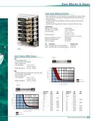
1.B.9. Unsafe Load Distribution<br />
Safety Information<br />
<strong>Sooner</strong> <strong>Trailers</strong><br />
Uneven load distribution can cause tire, wheel, axle or structural<br />
failure. Be sure your trailer is properly loaded.<br />
A proper weight distribution is equal, right to left; and creates a<br />
tongue weight that is in the proper range for stable trailer handling.<br />
For tandem and triple axle trailers, it is necessary to know or check<br />
that no axle is overloaded.<br />
In the table below, the second column notes the rule of thumb<br />
percentage of total weight of the trailer plus its cargo (Gross Vehicle<br />
Weight, or “GVW”) that should appear on the tongue of the trailer.<br />
For example, a trailer with a gooseneck hitch, with a loaded weight<br />
of 12,000 pounds, should have 20-25% of 12,000 pounds on the<br />
tongue. That is, the example trailer would have 2,400 to 3,000<br />
pounds on its tongue.<br />
Tongue Weight as a Percentage of Loaded Trailer Weight<br />
Type of Hitch<br />
Percentage<br />
Ball Hitch (or Bumper Hitch) 10-15%<br />
Gooseneck Hitch<br />
Fifth Wheel Hitch<br />
20-25%<br />
11
Safety Information<br />
<strong>Sooner</strong> <strong>Trailers</strong><br />
IMPROPER TONGUE WEIGHT (LOAD DISTRIBUTION) CAN RESULT<br />
IN LOSS OF CONTROL OF THE TRAILER, LEADING TO DEATH OR<br />
SERIOUS INJURY.<br />
MAKE CERTAIN THAT TONGUE WEIGHT IS WITHIN THE ALLOWABLE<br />
RANGE.<br />
BE SURE TO:<br />
• DISTRIBUTE THE LOAD FRONT-TO-REAR TO PROVIDE PROPER<br />
TONGUE WEIGHT (SEE CHART);<br />
• DISTRIBUTE THE LOAD EVENLY, RIGHT AND LEFT, TO AVOID TIRE<br />
OVERLOAD; AND<br />
• KEEP THE CENTER OF GRAVITY LOW.<br />
Towing stability also depends on keeping the center of gravity as low as<br />
possible. Load heavy items on the floor, and over the axles, but do not<br />
exceed the axle load rating (GAWR). When loading additional items be<br />
sure to maintain even side-to-side weight distribution and proper tongue<br />
weight.<br />
1.B.10. Shifting Cargo<br />
Since the trailer “ride” can be bumpy and rough, you must secure your<br />
cargo so that it does not shift while the trailer is being towed.<br />
SHIFTING CARGO CAN RESULT IN LOSS OF CONTROL OF THE<br />
TRAILER, AND CAN LEAD TO DEATH OR SERIOUS INJURY.<br />
TIE DOWN ALL LOADS WITH PROPER SIZED FASTENERS, ROPES,<br />
STRAPS, ETC.<br />
If the door latch is equipped with a catch that has a hole for a linchpin, use<br />
a linchpin to prevent the door latch from opening.<br />
12
Safety Information<br />
<strong>Sooner</strong> <strong>Trailers</strong><br />
IF THE DOOR OPENS, YOUR CARGO MAY BE EJECTED ONTO THE<br />
ROAD, RESULTING IN DEATH OR SERIOUS INJURY TO OTHER<br />
DRIVERS.<br />
ALWAYS SECURE THE DOOR LATCH AFTER CLOSING.<br />
PLACE A LINCHPIN IN THE CATCH<br />
1.B.11. Inappropriate Cargo<br />
Your trailer may be designed for specific cargo, for example, only for<br />
horses. If your trailer is designed for specific cargo, only carry that cargo<br />
in the trailer. A utility trailer must not be used to carry certain items, such<br />
as people, containers of hazardous substances or containers of flammable<br />
substances.<br />
DO NOT TRANSPORT PEOPLE INSIDE THE TRAILER, EVEN IF IT<br />
HAS LIVING QUARTERS. THE TRANSPORT OF PEOPLE PUTS THEIR<br />
LIVES AT RISK AND MAY BE ILLEGAL.<br />
DO NOT TRANSPORT FLAMMABLE, EXPLOSIVE, POISONOUS OR<br />
OTHER DANGEROUS MATERIALS IN YOUR TRAILER.<br />
EXCEPTIONS:<br />
• FUEL IN THE TANKS OF VEHICLES THAT ARE BEING TOWED.<br />
• FUEL STORED IN PROPER CONTAINERS USED IN TRAILER LIVING<br />
QUARTERS FOR COOKING OR HEATING.<br />
• FUEL STORED IN THE TANK OF AN ON-BOARD GENERATOR.<br />
13
Safety Information<br />
<strong>Sooner</strong> <strong>Trailers</strong><br />
1.B.12. Inoperable Brakes, Lights or Mirrors<br />
Be sure that the electric brakes and all of the lights on your trailer are<br />
functioning properly before towing your trailer. Electric brakes and lights on<br />
a trailer are controlled via a connection to the tow vehicle, generally a multipin<br />
electrical connector. Check the trailer tail-lights by turning on your tow<br />
vehicle headlights. Check the trailer brake lights by having someone step<br />
on the tow vehicle brake pedal while you look at trailer lights. Do the same<br />
thing to check the turn signal lights.<br />
If your trailer has electric brakes, your tow vehicle must have an electric<br />
brake controller that sends power to the trailer brakes. Before towing the<br />
trailer on the road, you must operate the brake controller while trying to pull<br />
the trailer in order to confirm that the electric brakes operate. For testing<br />
brakes, follow brake controllers recommended procedure.<br />
IMPROPER ELECTRICAL CONNECTION BETWEEN THE TOW VEHICLE<br />
AND THE TRAILER WILL RESULT IN INOPERABLE LIGHTS AND<br />
ELECTRIC BRAKES, AND CAN LEAD TO COLLISION.<br />
BEFORE EACH TOW:<br />
• CHECK THAT THE TAIL LIGHTS, BRAKE LIGHTS AND TURN<br />
SIGNALS WORK.<br />
• CHECK THAT THE ELECTRIC BRAKES WORK BY OPERATING THE<br />
BRAKE CONTROLLER INSIDE THE TOW VEHICLE.<br />
Standard mirrors usually do not provide adequate visibility for viewing traffic<br />
to the sides and rear a towed trailer. You must provide mirrors that allow<br />
you to safely observe approaching traffic.<br />
1.B.13. Hazards From Modifying Your Trailer<br />
Essential safety items can be damaged by altering your trailer. Even simply<br />
driving a nail or screw to hang something can damage an electrical circuit,<br />
LP gas line or other feature of the trailer.<br />
14
Safety Information<br />
<strong>Sooner</strong> <strong>Trailers</strong><br />
Before making any alteration to your trailer, contact your dealer or <strong>Sooner</strong><br />
Trailer Manufacturing Co. at (800) 256-6668 and describe the alteration you<br />
are contemplating.<br />
Alteration of the trailer structure or modification of mechanical, electrical,<br />
plumbing, heating or other systems on your trailer must be performed only<br />
by qualified technicians who are familiar with the system as installed on<br />
your trailer.<br />
1.B.14. Hazards to Horses (Horse Trailer)<br />
Before hauling a horse, you must be aware of its temperament.<br />
The layout of a horse trailer is designed to safely contain your horse. The<br />
trailer is equipped with stall dividers and tie rings to secure the horse, and<br />
has a rubber floor mat to keep shoed horses from slipping on the metal<br />
underfloor. Restraining a horse without using a combination of a tie-strap<br />
and stall dividers may result in serious injury or death to the horse.<br />
Before loading your horse, inspect the interior of the horse trailer to insure<br />
that no hazards are present. Read the section 3.b.2. Loading Horses<br />
(Horse Trailer) on page 69 of this manual for specific instructions regarding<br />
trailering of horses.<br />
WHEN A HORSE IS FRIGHTENED, IT IS CAPABLE OF INFLICTING<br />
SERIOUS INJURY OR DEATH TO A HUMAN HANDLER.<br />
KNOW YOUR HORSE’S TEMPERAMENT BEFORE ATTEMPTING TO<br />
TRAILER IT.<br />
HANDLING A HORSE THAT IS NOT TRAILER-ACCLIMATED MAY<br />
RESULT IN INJURY OR DEATH, OR DAMAGE TO YOUR TRAILER.<br />
DO NOT HAUL AN UNBROKEN HORSE IN THIS TRAILER.<br />
HORSES MUST HAVE A HALTER.<br />
15
Safety Information<br />
<strong>Sooner</strong> <strong>Trailers</strong><br />
FAILURE TO SECURE A HORSE USING A TIE STRAP MAY RESULT IN<br />
ITS SERIOUS INJURY OR DEATH.<br />
THE TRAILER INTERIOR MAY CONTAIN HAZARDS TO A HORSE THAT<br />
CAN RESULT IN ITS SERIOUS INJURY OR DEATH.<br />
BEFORE LOADING A HORSE, INSPECT THE TRAILER INTERIOR AND<br />
ADJUST OR REPAIR ALL LOOSE AND PROTRUDING FEATURES SUCH<br />
AS HANDLES, LOOSE OR BROKEN PARTS OR THE TRAILER, ETC.<br />
BEFORE TOWING TRAILER:<br />
• LOCK ALL STALL DIVIDERS.<br />
• BE SURE ALL SADDLES, TACK AND EQUIPMENT, AS WELL AS<br />
HORSE(S), ARE PREVENTED FROM BEING THROWN ABOUT.<br />
HAULING A HORSE IN A LIVESTOCK TRAILER MAY RESULT IN ITS<br />
SERIOUS INJURY OR DEATH.<br />
DO NOT CARRY A HORSE IN A LIVESTOCK TRAILER. USE A TRAILER<br />
DESIGNED TO CARRY HORSES.<br />
1.B.15. Hazards to Livestock (Livestock Trailer)<br />
A livestock trailer is designed for the safe transport of livestock, other than<br />
horses. It is not equipped for hauling horses.<br />
Before loading your livestock, inspect the interior of the livestock trailer<br />
to insure that no hazards are present. Read section , 3.B.3, “Loading<br />
16
Safety Information<br />
<strong>Sooner</strong> <strong>Trailers</strong><br />
LARGE ANIMALS ARE CAPABLE OF INFLICTING SERIOUS INJURY OR<br />
DEATH TO A HUMAN HANDLER.<br />
KNOW YOUR ANIMALS’ TEMPERAMENT BEFORE ATTEMPTING TO<br />
TRAILER THEM.<br />
HAULING A HORSE IN A LIVESTOCK TRAILER MAY RESULT IN ITS<br />
SERIOUS INJURY OR DEATH.<br />
DO NOT CARRY A HORSE IN A LIVESTOCK TRAILER. USE A TRAILER<br />
DESIGNED TO CARRY HORSES.<br />
Livestock (Livestock Trailer)” page 75 for specific instructions regarding<br />
trailering of livestock other than horses.<br />
1.B.16. Hazards from Accessories<br />
The “Accesories” chapter of this manual contains some information about<br />
certain optional accessories that may be on your trailer. Read and follow all<br />
of these instructions before operating the accessories. The major hazards<br />
from some of these accessories are:<br />
1.B.16.a. Drop-down Feed Doors<br />
• Some trailers are equipped with drop-down feed doors and windows that<br />
are useful to provide additional ventilation to horses. These drop-down<br />
doors are characterized as having a horizontal hinge along their bottom<br />
edge and opening toward the trailer exterior.<br />
• During deliberate lowering/opening of these drop-down doors, there is risk<br />
of hitting oneself on the head or forearm, or perhaps pinching. In some<br />
cases, the catch that holds the door closed is located high enough that a<br />
user must stand on a step stool or ladder to reach. When on a step stool,<br />
a user has an additional risk of losing balance or otherwise falling.<br />
17
Safety Information<br />
<strong>Sooner</strong> <strong>Trailers</strong><br />
• In order that the drop–down door be secure, it is important that the catch<br />
be fully engaged. Full engagement is sometimes not made because<br />
the catch mechanism does not freely move. Ensure the latch operates<br />
properly and is fully engaged while in the closed position.<br />
• The drop-down door can pose a hazard to people who are handling their<br />
Horse (s) outside the trailer. It is common that a horse trailer has horse<br />
tie rings on its exterior. It is important that the drop-down doors be fully<br />
latched in the up position or in the down position because unexpected<br />
dropping of a door can result in a concussion or broken bones to people<br />
working outside, near the trailer. The unexpected dropping of a door can<br />
also cause injury to the horse or it can be startled.<br />
1.B.16.b. Generator<br />
If your trailer is equipped with a gasoline, propane, LP, or diesel generator,<br />
you must have and follow the generator manufacturer’s instructions. You<br />
must also have one or more carbon monoxide detectors in the trailer’s<br />
accommodation spaces.<br />
Carbon Monoxide is an odorless gas that can cause death. Be certain<br />
exhaust from a running generator does not accumulate in or around your<br />
trailer, by situations such as:<br />
OPERATING GASOLINE, PROPANE, LP, AND DIESEL, GENERATORS<br />
CAN LEAD TO DEATH OR SERIOUS INJURY BY:<br />
• CARBON MONOXIDE<br />
• FIRE AND EXPLOSION<br />
• ELECTROCUTION<br />
HAVE A WORKING CARBON MONOXIDE DETECTOR IN THE<br />
ACCOMMODATION SPACES BEFORE OPERATING A GENERATOR.<br />
DO NOT REFUEL A RUNNING GENERATOR OR REFUEL NEAR<br />
IGNITION SOURCES.<br />
18
Safety Information<br />
<strong>Sooner</strong> <strong>Trailers</strong><br />
Being drawn in by fans or ventilators operated in a trailer;<br />
Prevailing wind;<br />
Being trapped between your trailer and other trailers, vehicles or<br />
buildings; or<br />
Being trapped between your trailer and, or in a snow bank, or other<br />
nearby objects.<br />
1.B.16.c. Shore Power<br />
“Shore Power” is the name given to connecting your trailer to a source<br />
of electrical power using an extension cord specifically designed for that<br />
purpose.<br />
SHORE POWER POSES A RISK OF DEATH DUE TO ELECTROCUTION<br />
OR FIRE.<br />
• ALWAYS USE AN ELECTRICAL CORD SPECIFICALLY DESIGNED<br />
FOR SHORE POWER CONNECTION. NEVER USE AN ORDINARY<br />
EXTENSION CORD.<br />
• ALWAYS CONNECT THE ELECTRICAL CORD TO A GROUNDED<br />
SOURCE OF SHORE POWER.<br />
• DO NOT REMOVE THE “THIRD PRONG” FROM THE SHORE POWER<br />
PLUG.<br />
• CONNECT ONLY TO SOURCE OF PROPER VOLTAGE.<br />
• MAKE CERTAIN POLARITY IS CORRECT.<br />
• DO NOT OVERLOAD ELECTRICAL CIRCUITS.<br />
• ALWAYS REPLACE FUSES OR CIRCUIT BREAKERS WITH CORRECT<br />
RATING.<br />
19
1.B.16.d. LP Gas Fuel System<br />
Safety Information<br />
<strong>Sooner</strong> <strong>Trailers</strong><br />
YOU CAN DIE OR BE BRAIN DAMAGED BY CARBON MONOXIDE.<br />
MAKE CERTAIN THE EXHAUST FROM LP APPLIANCES IS DIRECTED<br />
TO THE OUTDOORS.<br />
HAVE A WORKING CARBON MONOXIDE DETECTOR IN THE<br />
ACCOMMODATION SPACES OF YOUR TRAILER BEFORE OPERATING<br />
ANY LP GAS APPLIANCE.<br />
DO NOT OPERATE PORTABLE GRILLS OR STOVES INSIDE THE<br />
TRAILER.<br />
RISK OF DEATH DUE TO FIRE OR EXPLOSION.<br />
ONLY CONNECT AN LP GAS SYSTEM TO A SUPPLY OF LP GAS,<br />
NOT NATURAL GAS.<br />
DO NOT STORE LP GAS TANKS INSIDE THE TRAILER.<br />
ONLY FILL AN LP GAS TANK 80% FULL.<br />
ONLY FILL THE TANK WITH LP GAS (BUTANE OR PROPANE).<br />
OVERFILLED TANKS CAN RELEASE GAS AND CAUSE AN<br />
20
Safety Information<br />
<strong>Sooner</strong> <strong>Trailers</strong><br />
RISK OF FIRE OR EXPLOSION.<br />
IF LP GAS IS DETECTED (BY SMELL OR BY THE LP GAS<br />
DETECTOR):<br />
• DO NOT TOUCH ELECTRICAL SWITCHES<br />
• EXTINGUISH FLAMES AND PILOT LIGHTS<br />
• OPEN DOORS FOR VENTILATION<br />
• SHUT OFF LP GAS SUPPLY AT THE LP TANK<br />
• LEAVE THE AREA UNTIL ODOR CLEARS<br />
CORRECT THE SOURCE OF LP GAS LEAKAGE BEFORE USING LP<br />
APPLIANCES.<br />
DO NOT USE A FLAME TO LOCATE THE SOURCE OF AN LP GAS<br />
LEAK.<br />
RISK OF FIRE OR EXPLOSION.<br />
NEVER USE A FLAME, HEAT LAMP OR HAIR DRYER TO THAW AN<br />
LP GAS REGULATOR. USE AN INCANDESCENT LIGHT BULB.<br />
DO NOT REMOVE THE REGULATOR COVER OR ATTEMPT TO<br />
SERVICE THE LP GAS REGULATOR.<br />
1.B.17. Reporting Safety Defects<br />
If you believe that your vehicle has a defect that could cause a crash or<br />
could cause injury or death, you should immediately inform the National<br />
Highway Traffic Safety Administration (NHTSA) in addition to notifying us.<br />
If NHTSA receives similar complaints, it may open an investigation, and<br />
if it finds that a safety defect exists in a group of vehicles, it may order a<br />
recall and remedy campaign. However, NHTSA cannot become involved in<br />
individual problems between you, your dealer, or us.<br />
To contact NHTSA, you may either call the Auto Safety Hotline toll-free at<br />
21
Safety Information<br />
<strong>Sooner</strong> <strong>Trailers</strong><br />
1-800-424-9393 (or 366-0123 in Washington D.C. area) or write to: NHTSA,<br />
U.S. Department of Transportation, Washington, DC 20590. You can also<br />
obtain other information about motor vehicle safety from the Hotline.<br />
Call (800) 256-6668 to reach <strong>Sooner</strong> Trailer Manufacturing Co.<br />
TO PROTECT YOU AND OTHERS AGAINST DEATH OR SERIOUS<br />
INJURY, ALL OF THE LABELS SHOWN ON THE FOLLOWING PAGES<br />
MUST BE ON THE TRAILER AND MUST BE LEGIBLE.<br />
IF ANY OF THESE LABELS ARE MISSING OR CANNOT BE READ,<br />
CALL SOONER TRAILER MANUFACTURING CO. AT (800) 256-6668<br />
FOR FREE REPLACEMENT LABELS.<br />
YOU WILL NEED TO PROVIDE US WITH THE NUMBER SHOWN AT<br />
THE BOTTOM OF THE LABEL(S) IN ORDER FOR US TO SEND THE<br />
CORRECT ONE(S).<br />
1.B.18. Safety Warning Labels on Your Trailer<br />
1.B.18.a Labels for Bumper Pull and Gooseneck <strong>Trailers</strong><br />
Figure 1-1 #UT0019 Lugnut/wheel<br />
Figure 1-2 #UT0027 Electrical Connection<br />
22
Safety Information<br />
<strong>Sooner</strong> <strong>Trailers</strong><br />
Figure 1-3 #UT0024 Safe Load<br />
Figure 1-4<br />
SOT001 Wiring Diagram<br />
Figure 1-5<br />
SOT002 Floor Care<br />
23
Safety Information<br />
<strong>Sooner</strong> <strong>Trailers</strong><br />
DO NOT RIDE IN TRAILER WHILE IN MOTION. SEVERE INJURY CAN<br />
RESULT AS NO RESTRAINT DEVICES ARE AVAILABLE.<br />
DO NOT REMAIN IN TRAILER DRESSING ROOM WITH DOORS<br />
AND WINDOWS CLOSED WHILE TOWING VEHICLE IS RUNNING,<br />
STATIONARY OR IN MOTION. SEVERE INJURY OR DEATH CAN<br />
RESULT FROM TOWING VEHICLE EXHAUST FUMES ACCUMULATING<br />
IN TRAILER DRESSING ROOM.<br />
DO NOT USE AUXILIARY HEATING DEVICES IN NON-VENTED AREAS.<br />
CARBON MONOXIDE CAN ACCUMULATE IN THE DRESSING ROOM<br />
RESULTING IN SEVERE INJURY OR DEATH.<br />
Bumper Pull Trailer Warning Labels:<br />
Figure 1-6<br />
#UT 0030 Bull Dog Coupling Instructions<br />
24
Safety Information<br />
<strong>Sooner</strong> <strong>Trailers</strong><br />
Figure 1-7<br />
#UT 0036 Bumper Pull Safety Chain Instructions<br />
Figure 1-8<br />
#UT0037 Break Away Switch Testing<br />
25
Gooseneck Trailer Warning Labels:<br />
Safety Information<br />
<strong>Sooner</strong> <strong>Trailers</strong><br />
Figure 1-9<br />
#UT0015 Gooseneck Breakaway Switch Testing<br />
Figure 1-10<br />
#UT0021 Gooseneck Safety Chains<br />
1.B.19. Trailer Towing Guide<br />
Driving a vehicle with a trailer in tow is vastly different from driving the same<br />
vehicle without a trailer in tow. Acceleration, maneuverability and braking<br />
are all diminished with a trailer in tow. It takes longer to get up to speed,<br />
you need more room to turn and pass, and more distance to stop when<br />
towing a trailer. You will need to spend time adjusting to the different feel<br />
and maneuverability of the tow vehicle with a loaded trailer. Because of<br />
the significant differences in all aspects of maneuverability when towing<br />
a trailer, the hazards and risks of injury are also much greater than when<br />
driving without a trailer. You are responsible for keeping your vehicle and<br />
trailer in control, and for all the damage that is caused if you lose control of<br />
your vehicle and trailer.<br />
26
Safety Information<br />
<strong>Sooner</strong> <strong>Trailers</strong><br />
As you did when learning to drive an automobile, find an open area with<br />
little or no traffic for your first practice trailering. Of course, before you<br />
start towing the trailer, you must follow all of the instructions for inspection,<br />
testing, loading and coupling. Also, before you start towing, adjust the<br />
mirrors so you can see the trailer as well as the area to the rear of it.<br />
Drive slowly at first, 5 m.p.h. or so, and turn the wheel to get the feel of how<br />
the tow vehicle and trailer combination responds. Next, make some right<br />
and left hand turns. Watch in your side mirrors to see how the trailer follows<br />
the tow vehicle. Turning with a trailer attached requires more room.<br />
Stop the rig a few times from speeds no greater than 10 m.p.h. If your<br />
trailer is equipped with brakes, try using different combinations of trailer/<br />
electric brake and tow vehicle brake. Note the effect that the trailer brakes<br />
have when they are the only brakes used. When properly adjusted, the<br />
trailer brakes will come on just before the tow vehicle brakes.<br />
It will take practice to learn how to back up a tow vehicle with a trailer<br />
attached. Take it slow. Before backing up, get out of the tow vehicle and<br />
look behind the trailer to make sure that there are no obstacles. Some<br />
drivers place their hands at the bottom of the steering wheel, and while the<br />
tow vehicle is in reverse, “think” of the hands as being on the top of the<br />
wheel. When the hands move to the right (counter-clockwise, as you would<br />
do to turn the tow vehicle to the left when moving forward), the rear of the<br />
trailer moves to the right. Conversely, rotating the steering wheel clockwise<br />
with your hands at the bottom of the wheel will move the rear of the trailer<br />
to the left, while backing up. If you are towing a bumper hitch rig, be careful<br />
not to allow the trailer to turn too much, because it will hit the rear of the tow<br />
vehicle. To straighten the rig, either pull forward, or turn the steering wheel<br />
in the opposite direction.<br />
Safe Trailer Towing Guidelines:<br />
• Recheck the load tiedowns to make sure the load will not shift during<br />
towing.<br />
• Before towing, check coupling, safety chain, safety brake, tires, wheels<br />
and lights.<br />
• Check the lug nuts or bolts for tightness.<br />
• Check coupler tightness after towing 50 miles.<br />
27
Safety Information<br />
<strong>Sooner</strong> <strong>Trailers</strong><br />
• Adjust the brake controller to engage the trailer brakes before the tow<br />
vehicle brakes. Your dealer can assist you by making this adjustment.<br />
• Use your mirrors to verify that you have room to change lanes or pull<br />
into traffic.<br />
• Use your turn signals well in advance.<br />
• Allow plenty of stopping space for your trailer and tow vehicle.<br />
• Do not drive so fast that the trailer begins to sway due to speed. Never<br />
drive faster than 60 m.p.h.<br />
• Allow plenty of room for passing. A rule of thumb is that the passing<br />
distance with a trailer is 4 times the passing distance without a trailer.<br />
• Shift your automatic transmission into a lower gear for city driving.<br />
• Use lower gears for climbing and descending grades.<br />
• Do not ride the brakes while descending grades, they may get so hot<br />
that they stop working. Then you will potentially have a runaway tow<br />
vehicle and trailer.<br />
• To conserve fuel, don’t use full throttle to climb a hill. Instead, build<br />
speed on the approach.<br />
• Slow down for bumps in the road. Take your foot off the brake when<br />
crossing the bump.<br />
• Do not brake while in a curve unless absolutely necessary. Instead,<br />
slow down before you enter the curve and power through the curve.<br />
This way, the towing vehicle remains “in charge.”<br />
• Do not apply the brakes to correct extreme trailer swaying. Continued<br />
pulling of the trailer, and even slight acceleration, will provide a<br />
stabilizing force.<br />
• Make regular stops, about once each hour. Confirm that<br />
• the coupler is secure to the hitch and is locked,<br />
• electrical connections are made,<br />
• there is appropriate slack in the safety chains,<br />
• there is appropriate slack in the breakaway switch pullpin cable,<br />
• the tires are not visibly low on pressure, and<br />
• the cargo is secure and in good condition.<br />
28
2. Coupling to the Tow Vehicle<br />
Follow all of the safety precautions and instructions in this manual to ensure<br />
safety of persons, cargo, and satisfactory life of the trailer.<br />
2.A. Use an Adequate Tow Vehicle and Hitch<br />
If the vehicle or hitch is not properly selected and matched to the Gross<br />
Vehicle Weight Rating (GVWR) of your trailer, you can cause an accident<br />
that could lead to death or serious injury. If you already have a tow vehicle,<br />
know your vehicle tow rating and make certain your trailer rating is equal<br />
to or less than that of the tow vehicle. If you already have (or plan to buy)<br />
a trailer, make certain that the tow rating of the tow vehicle is equal to or<br />
greater than that of the trailer.<br />
USE OF A HITCH WITH A LOAD RATING LESS THAN THE LOAD<br />
RATING OF THE TRAILER CAN RESULT IN LOSS OF CONTROL AND<br />
MAY LEAD TO DEATH OR SERIOUS INJURY.<br />
USE OF A TOW VEHICLE WITH A TOWING CAPACITY LESS THAN THE<br />
LOAD RATING OF THE TRAILER CAN RESULT IN LOSS OF CONTROL,<br />
AND MAY LEAD TO DEATH OR SERIOUS INJURY.<br />
BE SURE YOUR HITCH AND TOW VEHICLE ARE RATED FOR THE<br />
GROSS VEHICLE WEIGHT RATING (GVWR) OF YOUR TRAILER.<br />
29
2A.1. Trailer Information<br />
Coupling to the Tow Vehicle<br />
The “Trailer VIN Tag” location figures (2-1, 2-2) shows the location of the<br />
Vehicle Identification Number (VIN) tag on your trailer.<br />
Figure 2-1 VIN Tag Location on Bumper Pull<br />
2-2a<br />
2-2b<br />
Figure 2-2 VIN Tag Location on Gooseneck<br />
30
Coupling to the Tow Vehicle<br />
Figure 2-3 VIN Tag Contents<br />
The trailer VIN tag(figure 2-3) contains the following critical safety<br />
information for the use of your trailer.<br />
VIN: The Vehicle Identification Number<br />
GVWR: The maximum allowable gross weight of the trailer and its<br />
contents. The gross weight of the trailer includes the weight of the trailer<br />
and all of the items within it (such as cargo, water, food and other supplies).<br />
GVWR is sometimes referred to as GTWR (Gross Trailer Weight Rating), or<br />
MGTW (Maximum Gross Trailer Weight). GVWR, GTWR and MGTW are<br />
all the same rating.<br />
GAWR: The maximum gross weight that an axle can support. It is the<br />
lowest of axle, wheel, or tire rating. Usually, the tire or wheel rating is lower<br />
than the axle rating, and determines GAWR.<br />
The sum total of the GAWR for all trailer axles may be less than the GVWR<br />
for the trailer, because some of the trailer load is to be carried by the tow<br />
vehicle, rather than by the trailer axle(s). The total weight of the cargo<br />
and trailer must not exceed the GVWR, and the load on an axle must not<br />
exceed its GAWR.<br />
PSI: The tire pressure (Pounds per Square Inch) measured when Cold.<br />
KG: Weight in Kilograms<br />
31
Coupling to the Tow Vehicle<br />
KPA: The tire pressure (kilopascals) measured when cold.<br />
EMPTY WEIGHT: Some information that comes with the trailer (such as<br />
the Manufacturer’s Statement of Origin) is not a reliable source for “empty”<br />
or “net” weight. The shipping documents list average or standard weights<br />
and your trailer may be equipped with options. To determine the “empty” or<br />
“net” weight of your trailer, weigh it on an axle scale. Because an axle scale<br />
weighs all axles, including the tow vehicle axles, and because some of the<br />
trailer weight will be transferred from the trailer to the tow vehicle axles, you<br />
must know the axle weights of your tow vehicle without the trailer coupled,<br />
to find the weight of the trailer use an axle scale.<br />
2A.2. Tow Vehicle<br />
When equipping a new vehicle or an older vehicle to tow your trailer, ask<br />
the vehicle dealer for advice on how to outfit the towing vehicle. Discuss<br />
the following information and equipment with the vehicle dealer.<br />
Overall Carrying and Towing Capacity of Vehicle<br />
Vehicle manufacturers will provide you with the maximum capacities of their<br />
various models. No amount of reinforcement will give a 100 horsepower,<br />
2,500 pound truck the towing capacity that a 300 horsepower, 5,000 pound<br />
truck has.<br />
Towing Hitch<br />
The towing hitch attached to your tow vehicle must have a capacity equal<br />
to or greater than the load rating of the trailer you intend to tow. The hitch<br />
capacity must also be matched to the tow vehicle capacity. Only your<br />
vehicle dealer can provide and install the proper hitch on your tow vehicle.<br />
Suspension System<br />
Sway bars, shock absorbers, heavy duty springs, heavy duty tires and other<br />
suspension components must be able to sufficiently serve the size and<br />
weight of the trailer that is going to be towed.<br />
32
Coupling to the Tow Vehicle<br />
Brake Controller<br />
The brake controller is part of the tow vehicle and is essential in the<br />
operation of the electric brakes on the trailer. <strong>Sooner</strong> Trailer provides<br />
electric brakes on trailers with a GVWR of 3,000 pounds or more. The<br />
brake controller is not the same as the safety breakaway brake system that<br />
may be equipped on the trailer.<br />
Side View Mirrors<br />
The size of the trailer that is being towed and your state law regulations<br />
determine the size of the mirrors. However, some states prohibit extended<br />
mirrors on a tow vehicle, except while a trailer is actually being towed. In<br />
this situation, detachable extended mirrors are necessary. Check with your<br />
dealer or the appropriate state agency for mirror requirements.<br />
Heavy Duty Flasher<br />
A Heavy Duty Flasher is an electrical component that may be required when<br />
your trailer turn signal lights are attached to the tow vehicle flasher circuit.<br />
Electrical Connector<br />
An Electrical Connector connects the light and brake systems on the trailer<br />
to the light and brake controls on the towing vehicle.<br />
Heavy Duty Engine Oil Cooling System<br />
The tow vehicle engine works harder when a trailer is being towed.<br />
Depending on the size of the trailer, you may need to install a separate<br />
engine oil cooler. Inadequate cooling may result in sudden engine failure.<br />
Ask the tow vehicle dealer if it is necessary to install a heavy duty cooling<br />
system.<br />
Automatic Transmission Oil Cooler<br />
The automatic transmission of a towing vehicle handles more power when a<br />
trailer is being towed. Inadequate cooling will shorten transmission life, and<br />
may result in sudden transmission failure. Ask the tow vehicle dealer if it is<br />
necessary to install a separate oil cooler for the automatic transmission.<br />
Fire Extinguisher<br />
It is sensible to have a fire extinguisher in the tow vehicle.<br />
33
Coupling to the Tow Vehicle<br />
Emergency Flares and Emergency Triangle Reflectors<br />
It is wise to carry these warning devices even if you are not towing a trailer.<br />
It is particularly important to have these when towing a trailer because the<br />
hazard flashers of your towing vehicle will not operate for as long a period<br />
of time when the battery is running both the trailer lights and tow vehicle<br />
lights.<br />
2.B. Coupling and Uncoupling the Trailer<br />
A secure coupling (or fastening) of the trailer to the tow vehicle is essential.<br />
A loss of coupling may result in death or serious injury. Therefore, you must<br />
understand and follow all of the instructions for coupling.<br />
The following parts are involved in making a secure coupling between the<br />
trailer and tow vehicle:<br />
Coupler: A device on the tongue of the trailer that connects to the hitch on<br />
the tow vehicle.<br />
Hitch: A device on the tow vehicle that supports the weight of the trailer<br />
tongue and pulls the trailer. The coupler attaches to the hitch.<br />
Safety chains: If the coupler connection comes loose, the safety chains can<br />
keep the trailer attached to the tow vehicle. With properly rigged safety<br />
chains, it is possible to keep the tongue of the trailer from digging into the<br />
road pavement, even if the coupler-to-hitch connection comes apart.<br />
Trailer lighting (and braking) connector: A device that connects electrical<br />
power from the tow vehicle to the trailer. Electricity is used to turn on brake<br />
lights, running lights, and turn signals as required. In addition, if your trailer<br />
has a separate electric braking system, the electrical connector will also<br />
supply power to the brakes from the tow vehicle.<br />
Breakaway switch: If the coupler connection comes loose, the breakaway<br />
switch can actuate emergency electrical brakes on the trailer. The<br />
breakaway switch must be rigged to the tow vehicle with appropriate slack<br />
that will activate the switch if the coupler connection comes loose.<br />
34
Coupling to the Tow Vehicle<br />
Jack: A device on the trailer that is used to raise and lower the coupler.<br />
The jack is sometimes called the “landing gear.”<br />
AN IMPROPERLY COUPLED TRAILER CAN RESULT IN DEATH OR<br />
SERIOUS INJURY.<br />
DO NOT MOVE THE TRAILER UNTIL:<br />
• THE COUPLER IS SECURED AND LOCKED TO HITCH;<br />
• THE SAFETY CHAINS ARE SECURED TO THE TOW VEHICLE; AND<br />
• THE TRAILER JACK(S) ARE FULLY RETRACTED.<br />
DO NOT TOW THE TRAILER ON THE ROAD UNTIL:<br />
• TIRES AND WHEELS ARE CHECKED;<br />
• THE TRAILER BRAKES ARE CHECKED;<br />
• THE BREAKAWAY SWITCH IS CONNECTED TO THE TOW VEHICLE;<br />
• THE LOAD IS SECURED TO THE TRAILER; AND<br />
• THE TRAILER LIGHTS ARE CONNECTED AND CHECKED.<br />
35
Coupling to the Tow Vehicle<br />
VARIOUS COUPLER DESIGNS . . .<br />
<strong>Trailers</strong> are produced with a variety of coupler devices. One of the sections<br />
below will pertain to your trailer.<br />
Ball Hitch Coupler<br />
Gooseneck Hitch Coupler<br />
If the coupler on your trailer does not resemble one of the couplers shown<br />
in the figures, see the separate coupler instructions. If you do not have<br />
separate coupler instructions, call for a free copy.<br />
2.B.1. Trailer with Ball-Hitch Coupler<br />
A ball hitch coupler connects to a ball that is located on or under the rear<br />
bumper of tow vehicle. This system of coupling a trailer to a tow vehicle is<br />
sometimes referred to as “bumper pull” (BP).<br />
A ball hitch trailer (figure 2-4) may be fitted with a tongue jack that can raise<br />
and lower the coupler. The tongue jack is mounted to the A-frame (front, or<br />
tongue) part of the trailer. By rotating the jack handle clockwise, the jack<br />
will extend and raise the tongue of the trailer.<br />
Figure 2-4 Trailer with Ball-hitch Coupler<br />
36
Coupling to the Tow Vehicle<br />
We have utilized a Ball Hitch coupler that is suitable for the size and weight<br />
of the trailer. The load rating of the coupler and the necessary ball size are<br />
listed on the trailer tongue. You must provide a hitch and ball for your tow<br />
vehicle, where the load rating of the hitch and ball is equal to or greater<br />
than that of your trailer. Also, the ball size must be the same as the coupler<br />
size. If the hitch ball is too small, too large, is underrated, is loose or is<br />
worn, the trailer can come loose from the tow vehicle, and may cause death<br />
or serious injury.<br />
THE TOW VEHICLE, HITCH AND BALL MUST HAVE A RATED TOWING<br />
CAPACITY EQUAL TO OR GREATER THAN THE TRAILER GVWR (Gross<br />
Vehicle Weight Rating).<br />
IT IS ESSENTIAL THAT THE HITCH BALL BE OF THE SAME SIZE AS<br />
THE COUPLER.<br />
The ball size and load rating (capacity) are marked on the ball; hitch<br />
capacity is marked on the hitch<br />
2B.1.a. Before coupling the trailer to the tow vehicle<br />
Be sure the size and rating of hitch ball match the size and rating of the<br />
coupler. Hitch balls and couplers are marked with their size and rating.<br />
COUPLER-TO-HITCH MISMATCH CAN RESULT IN UNCOUPLING,<br />
LEADING TO DEATH OR SERIOUS INJURY.<br />
BE SURE THE LOAD RATING OF THE HITCH BALL IS EQUAL OR<br />
GREATER THAN THE LOAD RATING OF THE COUPLER.<br />
BE SURE THE SIZE OF THE HITCH BALL MATCHES THE SIZE OF<br />
THE COUPLER.<br />
37
Coupling to the Tow Vehicle<br />
• Wipe the hitch ball clean and inspect it visually and by feel for flat spots,<br />
cracks and pits.<br />
A WORN, CRACKED OR CORRODED HITCH BALL CAN FAIL WHILE<br />
TOWING, AND MAY RESULT IN DEATH OR SERIOUS INJURY.<br />
BEFORE COUPLING TRAILER, INSPECT THE HITCH BALL FOR WEAR,<br />
CORROSION AND CRACKS.<br />
REPLACE WORN OR DAMAGED HITCH BALL.<br />
• Rock the ball to make sure it is tight to the hitch, and visually check that<br />
the hitch ball nut is solid against the lock washer and hitch frame.<br />
• Wipe the inside and outside of the coupler clean and inspect it visually for<br />
cracks and deformations; feel the inside of the coupler for worn spots and<br />
pits.<br />
• Be sure the coupler is tight to the tongue of the trailer. All coupler<br />
fasteners must be visibly solid against the trailer frame.<br />
• Use the jack to raise the bottom surface of the coupler to be above the top<br />
of the hitch ball.<br />
A LOOSE HITCH BALL NUT CAN RESULT IN UNCOUPLING, LEADING<br />
TO DEATH OR SERIOUS INJURY.<br />
BE SURE THE HITCH BALL IS TIGHT TO THE HITCH BEFORE<br />
COUPLING THE TRAILER.<br />
2.B.1.b. Prepare the coupler and hitch<br />
• Lubricate the hitch ball and the inside of the coupler with a thin layer of<br />
automotive bearing grease. With the jack, raise the coupler above the<br />
ball height.<br />
• Open the coupler locking mechanism (figure 2-5). Ball couplers have a<br />
locking mechanism with an internal moving piece and an outside handle.<br />
• In the open position, the coupler is able to drop fully into the hitch ball.<br />
38
Coupling to the Tow Vehicle<br />
• See the coupling instructions (figure 1-6) for details of placing the coupler<br />
in the “open” position (figure 2-5 a).<br />
• Slowly back up the tow vehicle so that the hitch ball is near or aligned<br />
under the coupler, if the trailer jack has raised the coupler.<br />
2-5a open 2-5b closed<br />
Figure 2-5 Ball Hitch Coupler Mechanism<br />
2.B.2. Couple the trailer to the tow vehicle<br />
• Using the jack, lower the trailer until the coupler fully engages the hitch<br />
ball. If the coupler does not line up with the hitch ball, adjust the position<br />
of the tow vehicle.<br />
• Engage the coupler locking mechanism (figure 1-6). In the engaged or<br />
“closed” position, (figure 2-5b) the locking mechanism securely holds the<br />
coupler to the hitch ball.<br />
• Insert a pin or lock through the hole in the locking mechanism.<br />
• Be sure the coupler is all the way on the hitch ball and the locking<br />
mechanism is engaged. A properly engaged locking mechanism will allow<br />
the coupler to raise the rear of the tow vehicle. Using the trailer jack, test<br />
to see that you can raise the rear of the tow vehicle by 1 inch, after the<br />
coupler is locked to the hitch.<br />
39
Coupling to the Tow Vehicle<br />
Overloading can damage the tongue jack. Do not use the<br />
tongue jack to raise the tow vehicle more than 1 inch.<br />
• If the coupler cannot be secured to the hitch ball, do not tow the trailer.<br />
Call <strong>Sooner</strong> Trailer Manufacturing Co. at (800) 256-6668 or your dealer<br />
for assistance.<br />
• Lower the trailer so that its entire tongue weight is held by the hitch, and<br />
continue retracting the jack to its fully retracted position.<br />
2.B.3. Rig the safety chains<br />
Figure 2-6 Safety Chain Arrangement on BP<br />
• Visually inspect the safety chains and hooks for wear or damage. If<br />
repairs are necessary, please take them to an authorized repair center.<br />
• Rig the safety chains (figure 1-7) so that they:<br />
1. cross underneath the coupler (figure 2-6);<br />
2. loop around a frame member of the tow vehicle or to holes provided<br />
in the hitch system (but, do not attach them to an interchangeable<br />
part of the hitch assembly); and<br />
40
Coupling to the Tow Vehicle<br />
3. have enough slack to permit tight turns, but not be close to the road<br />
surface, so if the trailer uncouples, the safety chains can hold the<br />
tongue up above the road.<br />
IMPROPER RIGGING OF THE SAFETY CHAINS CAN RESULT IN LOSS<br />
OF CONTROL OF THE TRAILER AND TOW VEHICLE, LEADING TO<br />
DEATH OR SERIOUS INJURY, IF THE TRAILER UNCOUPLES FROM<br />
THE TOW VEHICLE.<br />
• FASTEN CHAINS TO FRAME OF TOW VEHICLE. DO NOT FASTEN<br />
CHAINS TO ANY PART OF THE HITCH UNLESS THE HITCH HAS<br />
HOLES OR LOOPS SPECIFICALLY FOR THAT PURPOSE.<br />
• CROSS CHAINS UNDERNEATH HITCH AND COUPLER WITH<br />
ENOUGH SLACK TO PERMIT TURNING AND TO HOLD TONGUE UP,<br />
IF THE TRAILER COMES LOOSE.<br />
2.B.4. Attach and test electric breakaway brake system<br />
If the coupler or hitch fails, a properly connected and working breakaway<br />
brake system will apply electric brakes on the trailer. The safety chains will<br />
keep the tow vehicle attached and as the brakes are applied at the trailer’s<br />
axles, the trailer/tow vehicle combination will come to a controlled stop.<br />
The breakaway brake system includes a battery, a switch with a pullpin,<br />
and a breakaway brake controller. Read and follow the instructions here as<br />
well as the instructions that have been prepared by the breakaway brake<br />
controller manufacturer. If you do not have these instructions, call <strong>Sooner</strong><br />
Trailer Manufacturing Co. at (800) 256-6668 for a free copy.<br />
The breakaway brake system may be fitted with a charging facility that<br />
draws power from the tow vehicle. If the electrical system on your tow<br />
vehicle does not provide power to the breakaway brake battery, you must<br />
periodically charge the battery to keep the breakaway brake system in<br />
working order.<br />
41
Coupling to the Tow Vehicle<br />
Figure 2-7 Breakaway Brake BP Trailer<br />
• Connect the pullpin cable to the tow vehicle so that the pullpin will be<br />
pulled out before all of the slack in the safety chains is taken up (see<br />
Breakaway Brake System figure 1-8 and 2-7). Do not connect the<br />
pullpin cable to a safety chain or to the hitch ball or hitch ball assembly.<br />
This would keep the breakaway brake system from operating when it is<br />
needed.<br />
• Remove the pullpin from the switch and test tow the trailer, at less than<br />
5 m.p.h. You should feel the trailer resisting being towed, but the wheels<br />
will not necessarily be locked. If the brakes do not function, do not tow<br />
the trailer until brakes are repaired.<br />
• Immediately replace the pullpin. The breakaway brake system battery<br />
discharges rapidly when the pullpin is removed.<br />
AN INEFFECTIVE BREAKAWAY BRAKE SYSTEM CAN RESULT IN A<br />
RUNAWAY TRAILER, LEADING TO DEATH OR SERIOUS INJURY IF<br />
THE COUPLER OR BALL HITCH FAILS.<br />
CONNECT THE BREAKAWAY CABLE TO THE TOW VEHICLE; AND<br />
NOT TO THE HITCH, BALL OR SUPPORT.<br />
BEFORE TOWING THE TRAILER, TEST THE FUNCTION OF THE<br />
BREAKAWAY BRAKE SYSTEM. IF THE BREAKAWAY BRAKE SYSTEM<br />
IS NOT WORKING, DO NOT TOW THE TRAILER. HAVE IT SERVICED<br />
OR REPAIRED.<br />
42
Coupling to the Tow Vehicle<br />
Do not tow the trailer with the breakaway brake system ON because the<br />
brakes will overheat which can result in permanent brake failure.<br />
FAILURE TO REPLACE THE PULLPIN WILL PREVENT BRAKES FROM<br />
WORKING PROPERLY, LEADING TO LOSS OF CONTROL, SERIOUS<br />
INJURY OR DEATH.<br />
If you do not use your trailer for three or more months, or during winter<br />
months:<br />
• Store the battery indoors; and<br />
• Charge the battery every three months.<br />
Replace the breakaway brake battery according to intervals specified by<br />
manufacturer.<br />
2.B.5. Connect the electrical cables<br />
Connect the trailer lights to the tow vehicle’s electrical system using the<br />
electrical connectors (figure 1-2, 2-8).<br />
2-8 a 2-8 b<br />
(connected)<br />
(disconnected)<br />
Figure 2-8<br />
43
Coupling to the Tow Vehicle<br />
• Check all lights for proper operation with ignition on, parking brake set and<br />
the engine not running:<br />
• Clearance and Running Lights (Turn on tow vehicle headlights).<br />
• Brake Lights (Step on tow vehicle brake pedal).<br />
• Turn Signals (Operate tow vehicle directional signal lever).<br />
• Backup Lights (Put tow vehicle gear shift into reverse).<br />
• Check electric brakes for proper operation:<br />
If your trailer has electric brakes, your tow vehicle must have an<br />
electric brake controller that sends power to the trailer brakes. Before<br />
towing the trailer on the road, follow the brake controller manufacturer<br />
recommendations to test your trailer brakes.<br />
IMPROPER ELECTRICAL CONNECTION BETWEEN THE TOW VEHICLE<br />
AND THE TRAILER WILL RESULT IN INOPERABLE LIGHTS AND<br />
ELECTRIC BRAKES, AND CAN LEAD TO COLLISION.<br />
BEFORE EACH TOW:<br />
• CHECK THAT THE TAIL LIGHTS, BRAKE LIGHTS AND TURN<br />
SIGNALS WORK.<br />
• CHECK THAT THE ELECTRIC BRAKES WORK BY OPERATING THE<br />
BRAKE CONTROLLER INSIDE THE TOW VEHICLE.<br />
2.B.6. Uncoupling the Ball Hitch Trailer with Tongue Jack<br />
Follow these steps to uncouple your ball hitch trailer from the tow vehicle:<br />
• Block trailer tires to prevent the trailer from rolling, before jacking the trailer up.<br />
• Disconnect the electrical connector.<br />
• Disconnect the breakaway brake switch cable. Promptly replace the<br />
pullpin in the switchbox.<br />
• Disconnect the safety chains from the tow vehicle.<br />
• Unlock the coupler and open it.<br />
• Before extending jack, make certain the ground surface below the jack pad<br />
will support the tongue load.<br />
• Rotate the jack handle (or crank) clockwise. This will slowly extend the<br />
jack and transfer the weight of the trailer tongue to the jack.<br />
44
Coupling to the Tow Vehicle<br />
2.B.7. Trailer with Gooseneck Coupler and Drop-leg Jack<br />
A gooseneck coupler on the trailer connects to a gooseneck ball that you<br />
must have installed in the bed of the tow vehicle. This system of coupling a<br />
trailer to a tow vehicle permits the tow vehicle to turn to sharper angles than<br />
are permitted by a bumper hitch system. A gooseneck coupler consists of<br />
a tube in an inverted “U” shape and a gooseneck ball receiver. “Trailer with<br />
Gooseneck Hitch Coupler” figure 2-9.<br />
Figure 2-9 Trailer with Gooseneck Hitch Coupler<br />
We have utilized a Gooseneck ball receiver that is suitable for the size and<br />
weight of the trailer. The load rating of the coupler and the necessary ball<br />
size are listed on the gooseneck coupler.<br />
You must provide a gooseneck ball and support structure that is marked<br />
with a rating that meets or exceeds the GVW Rating of your trailer and<br />
matches the size of the gooseneck ball receiver. If the gooseneck ball is<br />
too small, is underrated, is loose or is worn, the trailer can come loose from<br />
the tow vehicle, and may lead to death or serious injury.<br />
THE TOW VEHICLE, SUPPORT STRUCTURE AND GOOSENECK BALL<br />
MUST HAVE A RATED TOWING CAPACITY EQUAL TO OR GREATER<br />
THAN THE TRAILER Gross Vehicle Weight Rating (GVWR).<br />
45
Coupling to the Tow Vehicle<br />
IT IS ESSENTIAL THAT THE GOOSENECK BALL BE OF THE SAME SIZE<br />
AS THE GOOSENECK BALL RECEIVER.<br />
The gooseneck ball size and load rating (capacity) are marked on the<br />
ball; hitch capacity is marked on the hitch.<br />
COUPLER-TO-HITCH MISMATCH CAN RESULT IN UNCOUPLING,<br />
LEADING TO DEATH OR SERIOUS INJURY.<br />
BE SURE THE LOAD RATING OF THE HITCH BALL IS EQUAL OR<br />
GREATER THAN THE LOAD RATING OF THE COUPLER.<br />
BE SURE THE SIZE OF THE HITCH BALL MATCHES THE SIZE OF<br />
THE COUPLER.<br />
The height of the ball receiver on the trailer must be adjusted to match the<br />
height of the gooseneck ball on your tow vehicle, so that:<br />
• There is clearance between the bottom of the trailer and the sides at<br />
the tow vehicle bed.<br />
• Some users of gooseneck trailers drive in rough terrain, where the tow<br />
vehicle and trailer are not level. If the un-level condition tilts the truck<br />
one direction and the trailer the opposite direction, the trailer and side<br />
of the truck can interfere, as they would if the gooseneck is set too<br />
low. When the truck and trailer is turning the likelihood of interference<br />
occurring is increased.<br />
• The remedy for this is to extend the gooseneck and possibly raise the<br />
frame of the trailer. The trailer must remain level on level ground, but<br />
the distance from the “bottom of the gooseneck” to the top sides of the<br />
truck bed is increased.<br />
• The adjustment to raise the trailer frame should be performed by a<br />
dealer or the trailer manufacturer, because the change involves a<br />
technical adjustment to the axle or replacing the axle with a different<br />
degree angle on the axle torsion arm.<br />
• The trailer is level and allows equal weight distribution on tandem and<br />
triple axles.<br />
46
Coupling to the Tow Vehicle<br />
The “Gooseneck Ball Receiver and Height Adjustment” figure 2-10 shows<br />
the gooseneck height adjustment. The gooseneck height adjustment bolts,<br />
which have a “cup” that makes a gripping impression into the gooseneck<br />
tube, must be tight so that the trailer does not drop to a lower position. Do<br />
not over-tighten because the tube can be deformed. After tightening the<br />
bolts, tighten the jam nuts on the bolts.<br />
Figure 2-10 Gooseneck Ball Receiver and Height Adjustment<br />
IMPROPER GOOSENECK HEIGHT ADJUSTMENT CAN RESULT IN<br />
OVERLOADED TIRES, BLOWOUT AND LOSS OF CONTROL, LEADING<br />
TO DEATH OR SERIOUS INJURY.<br />
ADJUST THE GOOSENECK RECEIVER SO THAT THE LOADED<br />
TRAILER IS LEVEL.<br />
A trailer having a gooseneck hitch will have one or two drop leg jacks for<br />
raising and lowering the gooseneck ball receiver. Because we use several<br />
drop leg jack mechanisms, the general instructions below may vary slightly<br />
from the jack manufacturer’s instructions. If the trailer jack on your trailer<br />
does not resemble the jack shown in the figures (2-11, 2-12, 2,13, 2-14),<br />
follow the jack instructions provided by the jack manufacturer. If you do<br />
not have these instructions, call <strong>Sooner</strong> Trailer Manufacturing Co. at<br />
(800) 256-6668 for a free copy.<br />
47
Coupling to the Tow Vehicle<br />
Figure 2-11 Drop-leg Jack Arrangement Binkley<br />
Figure 2-12 Drop-leg Jack Arrangement Stallion<br />
48
Coupling to the Tow Vehicle<br />
Figure 2-13 Drop-leg Jack Arrangement<br />
Binkley<br />
Figure 2-14 Drop-leg Jack Arrangement<br />
Binkley Spring Loaded<br />
49
Coupling to the Tow Vehicle<br />
Before attempting to tow the trailer:<br />
• Be sure the size and rating of the gooseneck ball match the size and<br />
rating of the receiver. Gooseneck and receivers are marked with their<br />
size and ratings.<br />
• Wipe the gooseneck ball clean and inspect it visually and by feel for flat<br />
spots, cracks and pits.<br />
A WORN, CRACKED OR CORRODED GOOSENECK BALL CAN FAIL<br />
WHILE TOWING, AND MAY RESULT IN DEATH OR SERIOUS INJURY.<br />
BEFORE COUPLING THE TRAILER, INSPECT THE GOOSENECK BALL<br />
FOR WEAR, CORROSION AND CRACKS; AND REPLACE WORN OR<br />
DAMAGED GOOSENECK BALL.<br />
• Rock the ball to make sure it is tight to the ball support, and visually check<br />
that the gooseneck ball nut is solid against the lock washer and ball<br />
support frame.<br />
A LOOSE GOOSENECK BALL CAN RESULT IN UNCOUPLING,<br />
LEADING TO DEATH OR SERIOUS INJURY.<br />
BE SURE THE GOOSENECK BALL NUT IS TIGHT BEFORE COUPLING<br />
THE TRAILER.<br />
• Wipe the inside and outside of the receiver clean and inspect it visually for<br />
cracks; and feel the inside of the receiver for worn spots and pits. If any<br />
of these conditions exist, have the receiver replaced before coupling the<br />
trailer.<br />
• Lubricate the inside of the gooseneck ball receiver with automotive bearing<br />
grease.<br />
• Be sure the receiver is tight to the trailer. All receiver fasteners must be<br />
visibly solid against the trailer frame.<br />
• Release the jack handle or crank from its holder (see “Drop Leg Jack”<br />
figure 2-21, 2-22).<br />
50
Coupling to the Tow Vehicle<br />
• Make certain the ground beneath the jack foot is firm enough to support<br />
the tongue weight.<br />
• Rotate the handle/crank clockwise to raise the bottom surface of the<br />
gooseneck to be above the top of the gooseneck ball.<br />
2.B.8. Prepare the ball receiver and gooseneck ball<br />
• Release the lock plate on the gooseneck ball receiver. With the springloaded<br />
lock plate locking pin in the OPEN position, rotate the lock plate to<br />
a position that allows the gooseneck ball to enter the receiver<br />
(figure 2-15a).<br />
2-15 a 2-15 b<br />
open<br />
closed<br />
Figure 2-15 Goose Neck Ball Receiver<br />
• Slowly back up the tow vehicle so that the goosneck ball is aligned<br />
under the gooseneck ball receiver.<br />
IF THE TRAILER DROPS DURING COUPLING, DEATH OR SERIOUS<br />
INJURY MAY RESULT.<br />
THERE MUST BE NO ONE UNDER THE TRAILER OR COUPLER<br />
BEFORE OR DURING THE COUPLING OPERATION.<br />
51
Coupling to the Tow Vehicle<br />
2.B.9. Couple the trailer to the tow vehicle<br />
• Rotate the jack handle counter-clockwise. This will retract the jack<br />
causing the gooseneck ball receiver to drop down so it can fully engage<br />
the gooseneck ball and transfer the weight of the trailer tongue to the<br />
towing vehicle hitch. If the receiver does not line up with the ball, raise<br />
the receiver again and adjust the position of the tow vehicle. Then lower<br />
the receiver over the ball. When the drop leg base is no longer resting on<br />
the ground, the towing vehicle hitch is holding all the weight of the trailer<br />
tongue.<br />
• Close the lock plate on the gooseneck ball receiver.<br />
• Move the spring-loaded lock plate locking pin to the CLOSED position. Be<br />
sure the locking pin is holding the lock plate (figure 2-15 b).<br />
• Be sure the receiver is all the way on the gooseneck ball and the lock<br />
plate is engaged. A properly engaged locking mechanism will allow the<br />
coupler to raise the rear of the tow vehicle. Using the trailer jack, test to<br />
see that you can raise the rear of the tow vehicle by 1 inch.<br />
^<br />
OVERLOADING CAN DAMAGE THE DROP LEG JACK. DO NOT USE<br />
THE DROP LEG JACK TO RAISE THE TOW VEHICLE MORE THAN 1<br />
INCH.<br />
If the goose neck ball cannot be secured to the receiver, do not tow the<br />
trailer, Call <strong>Sooner</strong> Trailer Manufacturing Co. at (800) 256-6668 or your<br />
dealer for assistance.<br />
• After testing to see that the receiver is properly secured and locked to<br />
the ball, retract the jack to its fully retracted position.<br />
Spring Loaded Jack<br />
• Spring loaded jack can be identified as not having a handle on the base<br />
foot of the jack (figure 2-16 a).<br />
• Return the drop legs to their upper positions. The drop legs are held<br />
in the lowered position with a loop handle that activates plunger pins.<br />
Rotating the loop handle down will cause the plunger pins to come out<br />
of engagement with the drop leg and the leg will rapidly rise if the jack<br />
is spring loaded (see “Drop Leg Mechanism” figure 2-16 b).<br />
52
Coupling to the Tow Vehicle<br />
2-16 a 2-16 b<br />
Figure 2-16<br />
Drop Leg Mechanism Binkley Spring Loaded<br />
THE DROP LEGS ARE HEAVILY SPRING LOADED IN THE LOWERED<br />
POSITION. THEY WILL RAPIDLY RETURN TO THE UPPER POSITION<br />
WHEN RELEASED AND CAN INFLICT SERIOUS BRUISES, SCRAPES<br />
OR PINCHING.<br />
KEEP YOUR FEET, SHINS AND HANDS WELL CLEAR OF THE DROP<br />
LEGS AND DROP LEG BASES WHEN RELEASING THE DROP LEGS.<br />
ALWAYS WEAR SHOES OR BOOTS WHILE PERFORMING THIS<br />
OPERATION.<br />
53
Coupling to the Tow Vehicle<br />
2-17 a 2-17 b<br />
Figure 2-17<br />
Drop Leg Mechanism Binkley <strong>Manual</strong><br />
<strong>Manual</strong> Jack<br />
• <strong>Manual</strong> jack drop leg can be identified by having a handle on the base<br />
leg of the jack (2-17b).<br />
• To raise the jack the plunger pin must be rotated to disengage the pin<br />
or the disengagement/engagement lever must be pushed downward or<br />
the loop handle must be pushed downward to disengage the pin (figure<br />
2-18 a,b,c). The drop leg must then be grabbed by the handle and<br />
pulled manually to the desired upward position. Rotate or raise the<br />
handle to engage the plunger pin securely.<br />
54
Coupling to the Tow Vehicle<br />
2-18 a 2-18b 2-18c<br />
Figure 2-18<br />
Releasing Drop Leg Mechanism<br />
2.B.10. Rig the safety chains<br />
• Visually inspect the safety chains and hooks for wear or damage. Replace<br />
worn or damaged safety chains and hooks with rated chains and hooks<br />
from sooner before towing.<br />
• Rig the safety chains so that they attach to the “safety chain receivers”<br />
on the hitch figure (1-11). If you are not certain of the hitch provisions for<br />
receiving safety chains, contact the hitch manufacturer or installer. Do NOT<br />
attach the safety chains to the gooseneck ball or its support; and<br />
• Rig the safety chains so they have sufficient slack to permit turning, but not<br />
too much slack - the safety chains must keep the gooseneck on the tow<br />
vehicle bed if the trailer uncouples.<br />
• IMPROPER RIGGING OF THE SAFETY CHAINS CAN RESULT IN LOSS<br />
OF CONTROL OF THE TRAILER AND TOW VEHICLE, LEADING TO<br />
DEATH OR SERIOUS INJURY, IF THE TRAILER UNCOUPLES FROM<br />
THE TOW VEHICLE.<br />
• FASTEN CHAINS TO SAFETY CHAIN RECEIVERS ON THE HITCH,<br />
NOT TO BALL.<br />
• HAVE SUFFICIENT SLACK TO PERMIT TRUNGIN AND TO KEEP<br />
GOOSENECK ON BED OF TRAILER, IF THE TRAILER COMES LOOSE.<br />
55
Coupling to the Tow Vehicle<br />
2.B.11. Attach and test the breakaway brake system<br />
If the coupler or hitch fails, a properly connected and working breakaway<br />
brake system will apply electric brakes on the trailer. The safety chains will<br />
keep the tow vehicle attached and as the brakes are applied at the trailer’s<br />
axles, the trailer/tow vehicle combination will come to a controlled stop.<br />
The breakaway brake system includes a battery, a switch with a pullpin,<br />
and a breakaway brake controller. Read and follow the instructions here as<br />
well as the instructions that have been prepared by the breakaway brake<br />
controller manufacturer. If you do not have these instructions, call <strong>Sooner</strong><br />
Trailer Manufacturing Co. at (800) 256-6668 for a free copy.<br />
Figure 2-19 Breakaway Brake System Gooseneck Coupler<br />
The breakaway brake system may be fitted with a charging facility that<br />
draws power from the tow vehicle. If the electrical system on your tow<br />
vehicle does not provide power to the breakaway brake battery you must<br />
periodically charge the battery on the trailer to keep the breakaway brake<br />
system in working order.<br />
• Visually inspect the breakaway brake system for broken parts.<br />
• Connect the pullpin cable to the tow vehicle so that the pullpin will be<br />
56
Coupling to the Tow Vehicle<br />
pulled out before all of the slack in the safety chains is taken up (see<br />
“Gooseneck Breakaway Switch Testing Figure 1-9). Do not connect<br />
the pullpin cable to a safety chain or a safety chain receiver or to<br />
the gooseneck ball or its support. This would keep the breakaway<br />
brake system from operating when it is needed. Contact the hitch<br />
manufacturer or installer if you are not certain of the hitch provisions for<br />
breakaway brake connection<br />
• Remove the pullpin from the switch and test tow the trailer at less than<br />
5 m.p.h. You should feel the trailer resisting being towed, but the<br />
wheels will not necessarily be locked.<br />
• Immediately replace the pullpin. The breakaway brake system battery<br />
discharges rapidly when the pullpin is removed.<br />
AN INEFFECTIVE OR INOPERATIVE BREAKAWAY BRAKE SYSTEM CAN<br />
RESULT IN A RUNAWAY TRAILER LEADING TO DEATH OR SERIOUS<br />
INJURY IF THE COUPLER OR HITCH FAILS.<br />
CONNECT THE BREAKAWAY CABLE TO THE TOW VEHICLE;<br />
AND NOT TO THE SAFETY CHAIN, SAFETY CHAIN RECEIVER,<br />
GOOSENECK BALL OR GOOSENECK BALL SUPPORT.<br />
TEST THE FUNCTION OF THE BREAKAWAY BRAKE SYSTEM<br />
BEFORE TOWING THE TRAILER. DO NOT TOW THE TRAILER IF THE<br />
BREAKAWAY BRAKE SYSTEM IS NOT WORKING. HAVE IT SERVICED<br />
OR REPAIRED.<br />
Do not tow the trailer with the breakaway brake system ON because the<br />
brakes will overheat which can result in permanent brake failure.<br />
FAILURE TO REPLACE THE PULL PIN WILL PREVENT BRAKES FROM<br />
WORKING, LEADING TO LOSS OF CONTROL, SERIOUS INJURY OR<br />
DEATH.<br />
If you do not use your trailer for three or more months, or during winter<br />
months:<br />
• Store the battery indoors; and<br />
• Charge the battery every three months.<br />
57
Coupling to the Tow Vehicle<br />
Replace the breakaway brake battery at intervals recommended by the<br />
battery manufacturer’s instructions.<br />
2.B.12. Connect the electrical cables<br />
Connect the trailer lights to the tow vehicle’s electrical system using the<br />
electrical connectors (figure 1-2).<br />
Check all lights for proper operation with the parking brake set, the ignition<br />
on and the engine not running:<br />
• Clearance and Running Lights (Turn on tow vehicle headlights).<br />
• Brake Lights (Step on tow vehicle brake pedal).<br />
• Turn Signals (Operate tow vehicle directional signal lever).<br />
• Backup Lights (Put tow vehicle gear shift into reverse).<br />
Check electric brakes for proper operation<br />
If your trailer has electric brakes, your tow vehicle will have an electric brake<br />
controller that sends power to the trailer brakes. Before towing the trailer on<br />
the road, you must operate the brake controller while trying to pull the trailer<br />
in order to confirm that the electric brakes operate. While towing the trailer<br />
at less than 5 m.p.h., manually operate the electric brake controller in the<br />
tow vehicle cab. You should feel the operation of the trailer brakes.<br />
2.B.13. Uncoupling the Gooseneck Trailer with Drop-leg Jack<br />
IMPROPER ELECTRICAL CONNECTION BETWEEN THE TOW VEHICLE<br />
AND THE TRAILER WILL RESULT IN INOPERABLE LIGHTS AND<br />
ELECTRIC BRAKES, AND CAN LEAD TO COLLISION.<br />
BEFORE EACH TOW:<br />
• CHECK THAT THE TAILLIGHTS, BRAKE LIGHTS AND TURN SIGNALS<br />
WORK<br />
• CHECK THAT THE ELECTRIC BRAKES WORK BY OPERATING THE<br />
BRAKE CONTROLLER INSIDE THE TOW VEHICLE<br />
Follow these steps to uncouple your gooseneck hitch trailer from the tow<br />
vehicle:<br />
58
• Block trailer tires to prevent the trailer from rolling, before jacking the<br />
trailer up<br />
• Disconnect the electrical connector.<br />
• Disconnect the breakaway brake switch cable. Promptly replace the<br />
pin in the switchbox.<br />
• Disconnect the safety chains from the tow vehicle.<br />
• Move the spring-loaded gooseneck receiver lock plate locking pin to the<br />
OPEN position (see “Gooseneck Ball Receiver and Height Adjustment”<br />
figure 2-15a).<br />
• Rotate the lock plate to a position that permits the gooseneck ball to<br />
exit the receiver.<br />
• Before releasing drop leg jack, make certain ground surface below jack<br />
base will support the trailer tongue load.<br />
Spring Loaded Jack<br />
Coupling to the Tow Vehicle<br />
• Rotate the plunger pin handle so that the plunger pin is released from<br />
the drop leg (see “Releasing Drop Leg Mechanism” figure 2-18a).<br />
• Push down on the drop leg base with your foot to place a drop leg to<br />
the desired lowered position.<br />
• Rotate the plunger pin handle so that the plunger pin is attempting to<br />
engage the drop leg (see “Engaging Drop Leg Mechanism” figure 2-20b).<br />
• Slowly raise your foot, permitting the drop leg to raise the drop leg. The<br />
plunger pin will engage a hole in the drop leg when the plunger pin<br />
handle is rotated to engage the drop leg.<br />
• If your trailer has two drop leg jacks, lower them both to the same level,<br />
following the above instructions.<br />
2-20 a 2-20 b 2-20 c<br />
Figure 2-20 Engaging Drop Leg Mechanism<br />
<strong>Manual</strong> Drop Leg Jack<br />
59
Coupling to the Tow Vehicle<br />
• THE DROP LEGS ARE HEAVILY SPRING LOADED IN THE LOWERED<br />
POSITION. THEY WILL RAPIDLY RETURN TO THE UPPER POSITION<br />
WHEN RELEASED AND CAN INFLICT SERIOUS BRUISES, SCRAPES<br />
OR PINCHING.<br />
• KEEP YOUR FEET, SHINS AND HANDS WELL CLEAR OF THE DROP<br />
LEGS AND DROP LEG BASES WHEN RELEASING THE DROP LEGS.<br />
• ALWAYS WEAR SHOES OR BOOTS WHILE PERFORMING THIS<br />
OPERATION.<br />
• While holding the drop leg handle, rotate the plunger pin handle or push<br />
down on the engagement/disengagement lever(loop handle) so the<br />
plunger pin is released from the drop leg (See “Releasing Drop Leg<br />
Mechanism” figure 2-18 a, b, c).<br />
• Lower the drop leg to the desired position.<br />
• Rotate the plunger pin handle or release the engagement/disengagement<br />
handle (loop handle) so that the plunger pin is attempting to engage the<br />
drop leg (see “Engaging Drop Leg Mechanism” figure 2-20 a, b, c).<br />
• Be sure the plunger pin is fully engaged. Push it in by hand if necessary.<br />
The bent part of the plunger pin handle must be touching the plunger pin<br />
housing or the engagement/disengagement lever must be released after<br />
which the lever will move upward, or the loop handle ends must be seated<br />
and hold handle up..<br />
• If your trailer has two drop leg jacks, lower them both to the same level,<br />
following the above instructions.<br />
• Release the handle (or crank) from its holder and engage it with the jack<br />
shaft (see figure 2-21,2-22).<br />
IF THE DROP LEGS ARE NOT SET AT THE SAME LEVEL, ONE<br />
OF THE DROP LEG JACKS CAN BE OVERLOADED AND CAN BE<br />
DAMAGED.<br />
60
Coupling to the Tow Vehicle<br />
Figure 2-21 Removable Handle<br />
• Rotate the handle (or crank) from its hold and engage it with the jack<br />
shaft.<br />
• Rotate the handle (or crank) clockwise to slowly extend the jack and<br />
transfer the weight of the trailer tongue to the jack.<br />
Figure 2-22 Jack Crank in Operating Position<br />
• On two speed jacks, pushing the handle shaft toward the gearbox can<br />
perform rapid extension. This shifts the gearbox into a high speed mode.<br />
• When the drop leg base contacts the ground, shift the gearbox into low<br />
speed mode by pulling out on the handle shaft until it locks into low gear.<br />
61
Coupling to the Tow Vehicle<br />
• Continue to extend the jack(s), making sure that the ground is providing<br />
stable and level support for the trailer.<br />
• After the jack(s) are extended and the gooseneck ball receiver is well clear<br />
of the gooseneck ball, to permit driving the tow vehicle away, disengage<br />
the handle from its shaft and return to its holder.<br />
DO NOT USE HIGH SPEED TO LIFT THE TRAILER, THE DROP LEG<br />
JACK MECHANISM CAN BE DAMAGED.<br />
HIGH SPEED IS USED ONLY TO RAPIDLY MOVE THE DROP LEG<br />
BASE INTO CONTACT WITH THE GROUND.<br />
62
3. Loading the Trailer<br />
Improper trailer loading causes many accidents and deaths. To safely load<br />
a trailer, you must consider:<br />
• Overall load weight;<br />
• Load weight distribution;<br />
• Proper tongue weight; and<br />
• Securing the load properly.<br />
To determine that you have loaded the trailer within its rating, you must<br />
consider the distribution of weight, as well as the total weight of the trailer<br />
and its contents. The trailer axles carry most of the total weight of the trailer<br />
and its contents (Gross Vehicle Weight, or “GVW”). The remainder of the<br />
total weight is carried by the tow vehicle hitch. It is essential for safe towing<br />
that the trailer tongue and tow vehicle hitch carry the proper amount of<br />
the loaded trailer weight, otherwise the trailer can suddenly sway wildly at<br />
towing speed. Read the “Tongue Weight” section below.<br />
The load distribution must be such that no component part of the trailer is<br />
loaded beyond its rating. This means that you must consider the rating<br />
of the tires, wheels and axles. For tandem and triple axle trailers, you<br />
must make sure that the front-to-rear load distribution does not result in<br />
overloading any axle.<br />
Towing stability also depends on keeping the center of gravity as low as<br />
possible. Load heavy items on the floor and over the axles. When loading<br />
additional items, be sure to maintain even side-to-side weight distribution<br />
and proper tongue weight. The total weight of the trailer and its contents<br />
must never exceed the total weight rating of the trailer (Gross Vehicle<br />
Weight Rating, or “GVWR”).<br />
AN OVERLOADED TRAILER CAN RESULT IN LOSS OF CONTROL OF<br />
THE TRAILER, LEADING TO DEATH OR SERIOUS INJURY.<br />
DO NOT EXCEED THE TRAILER GROSS VEHICLE WEIGHT RATING<br />
(GVWR) OR AN AXLE GROSS AXLE WEIGHT RATING (GAWR).<br />
DO NOT LOAD A TRAILER SO THAT THE WEIGHT ON ANY TIRE<br />
EXCEEDS ITS RATING.<br />
63
Loading the Trailer<br />
Tongue Weight<br />
It is critical to have a portion of the trailer load carried by the tow vehicle.<br />
That is, the trailer tongue must exert a downward force on the hitch. This<br />
is necessary for two reasons. First, the proper amount of tongue weight<br />
is necessary for the tow vehicle to be able to maintain control of the tow<br />
vehicle/trailer system. If, for example, the tongue exerts an upward pull on<br />
the hitch, instead of pushing down on it (because the trailer is overloaded<br />
behind its axle(s)), the rear wheel of the tow vehicle can lose traction or grip<br />
and cause loss of control. Also, even if there is some weight on the tongue,<br />
but not enough weight on the tongue, the trailer can suddenly become<br />
unstable at high speeds.<br />
If, on the other hand, there is too much tongue weight, the front wheels of<br />
the tow vehicle can be too lightly loaded and cause loss of steering control<br />
and traction, as well, if the front wheels are driving.<br />
In addition to tow vehicle control, tongue weight is necessary to insure that<br />
the trailer axle(s) do not exceed their Gross Axle Weight Rating (GAWR).<br />
The table below has “rules of thumb” for proper tongue weight.<br />
In the table below, the second column notes the rule of thumb percentage<br />
of total weight of the trailer plus its cargo (Gross Vehicle Weight, or “GVW”)<br />
that should appear on the tongue of the trailer. For example, a trailer with<br />
a gooseneck hitch, with a loaded weight of 12,000 pounds, should have<br />
20-25% of 12,000 pounds on the tongue. That is, the example trailer would<br />
have 2,400 to 3,000 pounds on its tongue.<br />
Tongue Weight as a Percentage of Loaded Trailer Weight<br />
Type of Hitch<br />
Percentage<br />
Ball Hitch (or Bumper Hitch) 10-15%<br />
Gooseneck Hitch<br />
Fifth Wheel Hitch<br />
20-25%<br />
64
Loading the Trailer<br />
IMPROPER TONGUE WEIGHT (LOAD DISTRIBUTION) CAN RESULT<br />
IN LOSS OF CONTROL OF THE TRAILER, LEADING TO DEATH OR<br />
SERIOUS INJURY.<br />
MAKE CERTAIN THAT TONGUE WEIGHT IS WITHIN THE ALLOWABLE<br />
RANGE.<br />
BE SURE TO:<br />
• DISTRIBUTE THE LOAD FRONT-TO-REAR TO PROVIDE PROPER<br />
TONGUE WEIGHT (SEE CHART);<br />
• DISTRIBUTE THE LOAD EVENLY, RIGHT AND LEFT, TO AVOID TIRE<br />
OVERLOAD; AND<br />
• KEEP THE CENTER OF GRAVITY LOW.<br />
3.A. Checking Tongue Weight<br />
To check the tongue weight, the tow vehicle and trailer must be on level<br />
ground, as they will be when the trailer is being towed.<br />
If you know the weight on your tow vehicle axles when you are not towing a<br />
trailer, trailer tongue weight can be determined with the use of a truck axle<br />
scale.<br />
3.B. Securing the Cargo<br />
Since the trailer “ride” can be bumpy and rough, you must secure your<br />
cargo so that it does not shift while the trailer is being towed.<br />
3.B.1. Loading Cargo (Enclosed Trailer)<br />
Couple the trailer to the tow vehicle before loading. The tongue of a<br />
bumper pull trailer can rise during loading, before the cargo is properly<br />
distributed. To measure the tongue weight, you will have to uncouple the<br />
trailer after it is loaded.<br />
Do not transport people, containers of hazardous substances, cans or<br />
containers of flammable substances. However, fuel in the tank of an off-road<br />
vehicle, or a car or motorcycle, etc., may be carried inside of your enclosed<br />
cargo trailer.<br />
65
Loading the Trailer<br />
DO NOT TRANSPORT PEOPLE INSIDE THE TRAILER, EVEN IF IT HAS<br />
LIVING QUARTERS. THE TRANSPORT OF PEOPLE PUTS THEIR LIVES<br />
AT RISK AND MAY BE ILLEGAL.<br />
DO NOT TRANSPORT FLAMMABLE, EXPLOSIVE, POISONOUS OR<br />
OTHER DANGEROUS MATERIALS IN YOUR TRAILER.<br />
EXCEPTIONS:<br />
• FUEL IN THE TANKS OF VEHICLES THAT ARE BEING TOWED<br />
• FUEL STORED IN PROPER CONTAINERS USED IN TRAILER LIVING<br />
QUARTERS FOR COOKING<br />
• FUEL STORED IN THE TANK OF AN ON-BOARD GENERATOR<br />
3.B.1.a. Preparing the Trailer for Loading<br />
Before loading cargo into your enclosed trailer, inspect the interior of the<br />
trailer.<br />
Enclosed trailers may be fitted with “D”-ring hold-downs, and/or a track<br />
system that can be used to secure the cargo. Inspect the “D”-rings and<br />
track system for looseness or signs of bending before loading the cargo<br />
onto the trailer.<br />
66
Loading the Trailer<br />
DAMAGED OR LOOSE “D”-RINGS CAN BREAK, ALLOWING CARGO TO<br />
BECOME LOOSE INSIDE THE TRAILER. LOOSE CARGO CAN SHIFT<br />
THE CENTER OF GRAVITY, AND RESULT IN LOSS OF CONTROL OF<br />
THE TRAILER.<br />
INSPECT “D”-RINGS, AND TEST THEM FOR LOOSENESS BEFORE<br />
LOADING CARGO.<br />
DO NOT USE A DAMAGED OR LOOSE “D”-RING TO SECURE CARGO.<br />
3.B.1.b. Loading the Enclosed Trailer<br />
Enclosed trailers may be fitted with a drop ramp door. The weight of the<br />
drop ramp door may be partially held by a spring and cable counterbalance<br />
assembly. If this assembly is out of adjustment or worn out, it will not<br />
provide the expected assistance for slow and careful lowering and raising of<br />
ramp.<br />
A SPRING AND CABLE COUNTERBALANCE CAN INFLICT SERIOUS<br />
INJURY IF IT BREAKS, OR IF INCORRECTLY ADJUSTED.<br />
INSPECT THE CABLE AND CABLE ENDS EACH TIME THE DOOR IS<br />
OPERATED.<br />
DO NOT ATTEMPT TO SERVICE THE COUNTERBALANCE. TAKE THE<br />
TRAILER TO YOUR DEALER FOR SERVICE.<br />
• Carefully lower the drop ramp to the ground.<br />
• Load the cargo up the drop ramp and into the trailer. If the trailer has<br />
living quarters, the cargo area of your trailer will have ventilation openings<br />
near the floor. Do not block these ventilation openings. These openings<br />
are provided to exhaust potentially deadly fumes.<br />
67
Loading the Trailer<br />
ACCUMULATION OF HAZARDOUS FUMES CAN CAUSE DEATH OR<br />
SERIOUS INJURY.<br />
DO NOT BLOCK ACCESS TO VENTILATION PORTS.<br />
• Secure the cargo to the trailer using appropriate straps, chains and<br />
tensioning devices.<br />
• Close the drop ramp door and secure the trailer door catch using a<br />
linchpin or other locking device, so that the catch and door cannot open<br />
while the trailer is being towed.<br />
Figure 3-1<br />
Cargo handle with lock<br />
IF THE DOOR OPENS, YOUR CARGO MAY BE EJECTED ONTO THE<br />
ROAD, RESULTING IN DEATH OR SERIOUS INJURY TO OTHER<br />
DRIVERS.<br />
ALWAYS SECURE THE DOOR LATCH AFTER CLOSING.<br />
PLACE A LINCHPIN IN THE CATCH, AND/OR LOCK.<br />
68
3.B.2. Loading Horses (Horse Trailer)<br />
Loading the Trailer<br />
Couple the trailer to the tow vehicle before loading. This is essential for<br />
the bumper pull trailer because the tongue of a bumper pull trailer can rise<br />
during loading, before the cargo is properly distributed.<br />
The cargo-carrying portion of a horse trailer is designed only for carrying<br />
horses. Do not transport people, livestock, containers of hazardous<br />
substances, or containers of flammable substances.<br />
DO NOT TRANSPORT PEOPLE INSIDE THE TRAILER, EVEN IF IT HAS<br />
LIVING QUARTERS. THE TRANSPORT OF PEOPLE PUTS THEIR LIVES<br />
AT RISK AND MAY BE ILLEGAL.<br />
DO NOT CARRY “LOOSE” LIVESTOCK IN YOUR HORSE TRAILER.<br />
THEY CAN CAUSE THE TRAILER TO BECOME UNSTABLE AND CAN<br />
RESULT IN LOSS OF CONTROL.<br />
YOU MUST USE A TRAILER DESIGNED TO CARRY “LOOSE”<br />
LIVESTOCK.<br />
Before loading a horse in your trailer, inspect the interior of the trailer. The<br />
interior of the trailer must be smooth, and have no protruding objects.<br />
There should be no loose objects that could move about and startle or<br />
injure the horse. Check the walls, floor, dividers, etc., for loose and broken<br />
parts, welds, hinges, etc.<br />
3.B.2.a. Preparing the Horse Trailer for Loading<br />
Open windows and vents to provide ventilation. Consider the weather<br />
and transport conditions (i.e. on warm sunny days, maximum ventilation is<br />
required). Do not carry a horse without providing ventilation, even in coldest<br />
weather. Ventilation is critical for the well being of your horses. Know your<br />
horses and adjust ventilation for your horses’ comfort.<br />
69
Loading the Trailer<br />
Be sure pivoting window latches are in a flush position, so they do not<br />
present a protrusion that can injure your horse.<br />
Tighten any loose or protruding screws in the walls.<br />
Remove or secure loose objects, (i.e. butt bars, saddles, tack and<br />
equipment) so that items will not move during towing.<br />
Inspect for cracks at the welds on the divider hinges, and the welds on<br />
the tie rings. If you are able to open any cracks in or near these welds by<br />
lifting the dividers or by twisting the tie rings, have the weld repaired before<br />
loading your horses.<br />
THE TRAILER INTERIOR MAY CONTAIN HAZARDS TO A HORSE THAT<br />
CAN RESULT IN ITS SERIOUS INJURY OR DEATH.<br />
BEFORE LOADING A HORSE, INSPECT THE TRAILER INTERIOR AND<br />
ADJUST OR REPAIR ALL LOOSE AND PROTRUDING FEATURES SUCH<br />
AS HANDLES, LOOSE OR BROKEN PARTRS OF THE TRAILER, ETC.<br />
BEFORE TOWING TRAILER:<br />
• LOCK ALL STALL DIVIDERS.<br />
• BE SURE ALL SADDLES, TACK AND EQUIPMENT, AS WELL AS<br />
HORSE(S), ARE PREVENTED FROM BEING THROWN ABOUT.<br />
IMPROPER WELD REPAIR WILL LEAD TO EARLY FAILURE OF THE<br />
TRAILER STRUCTURE AND CAN CAUSE SERIOUS INJURY OR DEATH.<br />
DO NOT REPAIR CRACKED OR BROKEN WELDS UNLESS YOU HAVE<br />
THE SKILLS AND EQUIPMENT TO MAKE A PROPER REPAIR. HAVE<br />
THE WELDS REPAIRED BY YOUR DEALER.<br />
3.B.2.b. Loading the Horse Trailer<br />
The trailering of horses introduces many variables that are not present in<br />
the trailering of non-living cargo. Horses are prone to take flight when they<br />
feel threatened or pain. In the confines of a trailer, the flight response can<br />
cause serious injury or death to a human handler. Even experienced and<br />
docile horses can be frightened.<br />
70
Loading the Trailer<br />
Horses must be slowly acclimated to trailering. Be sure the horse’s first<br />
trips are short trips, so you can gauge its reaction. Some will take to the<br />
experience easily, but others will strongly protest. You must act according<br />
to your horse’s demeanor.<br />
WHEN A HORSE IS FRIGHTENED, IT IS CAPABLE OF INFLICTING<br />
SERIOUS INJURY OR DEATH TO A HUMAN HANDLER.<br />
KNOW YOUR HORSE’S TEMPERAMENT BEFORE ATTEMPTING TO<br />
TRAILER IT.<br />
HANDLING A HORSE THAT IS NOT TRAILER-ACCLIMATED MAY<br />
RESULT IN INJURY OR DEATH, OR DAMAGE TO YOUR TRAILER.<br />
DO NOT HAUL AN UNBROKEN HORSE IN THIS TRAILER.<br />
HORSES MUST HAVE A HALTER.<br />
1. Open all stall dividers and lock them in their OPEN (against the wall)<br />
position.<br />
2. If the trailer has living quarters, close and lock the door between the living<br />
quarters and the horse area.<br />
3. If the trailer is fitted with a drop ramp, carefully lower it to the ground.<br />
4. If your trailer is fitted with swinging loading doors, open them fully and<br />
fasten them against the side of the trailer using the door holdbacks.<br />
5. Lead the horse into the trailer by a halter and lead rope. If the horse<br />
shows any signs of distress, stop loading, and calm the horse.<br />
IMPROPER WEIGHT DISTRIBUTION OF THE HORSES IN THE TRAILER<br />
WILL RESULT IN AN UNSTABLE TRAILER.<br />
ALWAYS LOAD THE FIRST HORSE INTO THE FORWARD-MOST STALL.<br />
6. Tie the horse to the trailer interior by fastening the quick connect or tying<br />
the lead rope to the tie ring, or other facility provided on the trailer wall for<br />
attachment of the lead rope. A rule of thumb is to leave about 18 inches<br />
of free rope between the attachment point on the trailer and the horse.<br />
The layout of the horse trailer has been designed to safely contain your<br />
71
Loading the Trailer<br />
horse. The trailer is equipped with stall dividers and tie rings to secure<br />
the horse, and has a rubber floor mat to keep shoed horses from slipping<br />
on the metal underfloor. Restraining a horse without using a combination<br />
of a tie-strap and stall divider may result in serious injury or death to the<br />
horse.<br />
FAILURE TO SECURE A HORSE USING A TIE STRAP MAY RESULT IN<br />
ITS SERIOUS INJURY OR DEATH.<br />
7. Close and lock the stall divider (figure 3-2).<br />
Figure 3-2<br />
Stall Divider Locked<br />
If additional horses are to be loaded, repeat steps 5-7 above for each horse<br />
- lead the horse, secure the horse, close and lock the stall divider.<br />
After the last horse has been loaded, lock any unused dividers in the<br />
CLOSED (across the trailer) position.<br />
Double check that each horse is tied to the trailer and each stall divider is<br />
LOCKED in the CLOSED position.<br />
If your trailer is fitted with a butt bar or butt strap to keep the horse away<br />
from the door, hook and lock the butt bar in place.<br />
72
Loading the Trailer<br />
Figure 3-3<br />
Butt Bar<br />
Close the trailer. Remove the door holdbacks and swing the hinged doors<br />
to a closed position, or raise the drop ramp.<br />
Secure the trailer door catch with a linchpin or similar device, so that the<br />
catch and door cannot open while the trailer is being towed (Figure 3-4<br />
and 3-1).<br />
Figure 3-4<br />
Secure with Pin<br />
73
Loading the Trailer<br />
Figure 3-5<br />
Boomer Cam Latch<br />
If your trailer is fitted with feed doors, close and secure them.<br />
IF THE DOOR OPENS, YOUR CARGO MAY BE EJECTED ONTO THE<br />
ROAD, RESULTING IN DEATH OR SERIOUS INJURY TO OTHER<br />
DRIVERS.<br />
ALWAYS SECURE THE DOOR LATCH AFTER CLOSING.<br />
PLACE A LINCHPIN IN THE CATCH.<br />
Check the horses after 5 to 10 miles or 10 minutes of towing, and then at<br />
least once per hour thereafter. Open a feed door or other access and look<br />
for signs of stress, cuts, or injury.<br />
HORSES MAY KICK WHEN BACK DOOR IS OPENED.<br />
STAY CLEAR WHEN OPENING BACK DOOR.<br />
74
Loading the Trailer<br />
3.B.3. Loading Livestock (Livestock Trailer)<br />
Couple the trailer to the tow vehicle before loading. This is essential for<br />
the bumper pull trailer because the tongue of a bumper pull trailer can rise<br />
during loading, before the cargo is properly distributed.<br />
The cargo-carrying portion of a livestock trailer is for carrying livestock<br />
(other than horses) only. The livestock trailer does not have the equipment<br />
required for the safe transport of horses, e.g. stall dividers, tie rings and<br />
a rubber floor mat. Do not transport people, containers of hazardous<br />
substances, or containers of flammable substances.<br />
DO NOT TRANSPORT PEOPLE INSIDE THE TRAILER, EVEN IF IT HAS<br />
LIVING QUARTERS. THE TRANSPORT OF PEOPLE PUTS THEIR LIVES<br />
AT RISK AND MAY BE ILLEGAL.<br />
DO NOT TRANSPORT FLAMMABLE, EXPLOSIVE, POISONOUS OR<br />
OTHER DANGEROUS MATERIALS IN YOUR TRAILER.<br />
EXCEPTIONS:<br />
• FUEL IN THE TANKS OF VEHICLES THAT ARE BEING TOWED<br />
• FUEL STORED IN PROPER CONTAINERS USED IN TRAILER LIVING<br />
QUARTERS FOR COOKING<br />
• FUEL STORED IN THE TANK OF AN ON-BOARD GENERATOR<br />
HAULING A HORSE IN A LIVESTOCK TRAILER MAY RESLUT IN ITS<br />
SERIOUS INJURY OR DEATH.<br />
DO NOT CARRY A HORSE IN A LIVESTOCK TRAILER.<br />
USE A TRAILER DESIGNED TO CARRY HORSES.<br />
75
Loading the Trailer<br />
3.B.3.a. Preparing the Livestock Trailer for Loading<br />
Before loading livestock in your livestock trailer, inspect the interior of the<br />
trailer. The interior of the trailer must be smooth, and have no protruding<br />
objects, such as bolts, broken parts of trailer interior, etc. A protruding<br />
object can injure your livestock.<br />
Tighten any loose or protruding bolts in the walls.<br />
Remove or secure loose objects, so no items will move during towing.<br />
THE INTERIOR SPACE OF A TRAILER MAY CONTAIN HAZARDS THAT<br />
RESULT IN SERIOUS INJURY OR DEATH TO TRAILERED LIVESTOCK.<br />
INSPECT THE INTERIOR OF THE TRAILER BEFORE LOADING<br />
LIVESTOCK.<br />
• ADJUST OR REPAIR ALL LOOSE AND PROTRUDING FEATURES.<br />
• ALL CARGO AND EQUIPMENT, BESIDES THE LIVESTOCK, MUST BE<br />
PREVENTED FROM BEING THROWN ABOUT BEFORE TOWING.<br />
3.B.3.b. Loading the Livestock Trailer<br />
The trailering of livestock introduces many variables that are not present in<br />
the trailering of non-living cargo. Livestock may resist being loaded into a<br />
trailer.<br />
LARGE ANIMALS ARE CAPABLE OF INFLICTING SERIOUS INJURY OR<br />
DEATH TO A HUMAN HANDLER.<br />
KNOW YOUR ANIMALS’ TEMPERMENT BEFORE ATTEMPTING TO<br />
TRAILER THEM.<br />
If the trailer is fitted with a drop ramp, carefully lower it to the ground.<br />
With the trailer in position, open and secure the loading door (either<br />
swinging, sliding or roll-up).<br />
• Open and secure the interior gates as necessary.<br />
• Guide the livestock into the trailer.<br />
76
Loading the Trailer<br />
• Gate the livestock tightly to keep them from moving or falling during<br />
transportation.<br />
• Close the loading doors (either swinging , sliding or roll-up) and raise the<br />
drop ramp.<br />
• Secure the trailer door catch with a linchpin or similar device, so that the<br />
catch and door cannot open while the trailer is being towed (figure 3-4).<br />
IF THE DOOR OPENS, YOUR CARGO MAY BE EJECTED ONTO THE<br />
ROAD, RESULTING IN DEATH OR SERIOUS INJURY TO OTHER<br />
DRIVERS.<br />
ALWAYS SECURE THE DOOR LATCH AFTER CLOSING.<br />
PLACE A LINCHPIN IN THE CATCH.<br />
77
4. Checking the Trailer Before and During Each Tow<br />
4.A. Pre-Tow Checklist<br />
Before towing, double-check all of these items:<br />
Tires, wheels and lug nuts (see the “Major Hazards” section starting on<br />
page 4 of this manual)<br />
Coupler secured and locked (see the “Coupling and Uncoupling the<br />
Trailer” section starting on page 34 of this manual)<br />
Safety chains properly rigged to tow vehicle, not to hitch or ball (see the<br />
“Coupling to the Tow Vehicle” chapter starting at Page 29 of this manual)<br />
Test of lights: Tail, Stop, Turn and Backup<br />
Safety breakaway switch cable fastened to tow vehicle, not to safety<br />
chains (see the “Coupling to the Tow Vehicle” chapter starting at Page 29<br />
of this manual)<br />
Cargo properly loaded, balanced and tied down (see the “Loading the<br />
Trailer” chapter starting at page 63 of this manual)<br />
Tongue weight<br />
Doors and gates latched and secured<br />
Fire extinguisher<br />
Flares and reflectors<br />
4.B. Make Regular Stops<br />
After each 50 miles, or one hour of towing, stop and check the following<br />
items:<br />
Coupler secured<br />
Safety chains are fastened and not dragging<br />
Cargo secured<br />
Cargo door latched and secured<br />
78
5. Breaking-In a New Trailer<br />
5.A. Retighten Lug Nuts at First 10, 25 & 50 Miles<br />
Wheel lugs can shift and settle quickly after being first assembled, and must<br />
be checked after the first 10, 25 and 50 miles of driving. Failure to perform<br />
this check may result in a wheel coming loose from the trailer, causing a<br />
LUG NUTS ARE PRONE TO LOOSEN AFTER INITIAL INSTALLATION,<br />
WHICH CAN LEAD TO DEATH OR SERIOUS INJURY.<br />
CHECK LUG NUTS FOR TIGHTNESS ON A NEW TRAILER OR WHEN<br />
WHEEL(S) HAVE BEEN REMOUNTED AFTER THE FIRST 10, 25 AND<br />
50 MILES OF DRIVING<br />
crash leading to death or serious injury (Figure 7-8).<br />
5.B. Adjust Brake Shoes at First 200 Miles<br />
Brake shoes and drums experience a rapid initial wear. The brakes<br />
must be adjusted after the first 200 miles of use, and each 3,000 miles<br />
thereafter. Some axles are fitted with a mechanism that will automatically<br />
adjust the brake shoes when the trailer is “hard braked” from a forward<br />
direction. Read your axle and brake manual to see if your brakes adjust<br />
automatically. If you do not have the axle and brake manual, call <strong>Sooner</strong><br />
Trailer Manufacturing Co. at (800) 256-6668 for a free copy.<br />
A hard stop is used to:<br />
• confirm that the brakes work;<br />
• confirm that the trailer brakes are properly synchronized with the tow<br />
vehicle brakes; and for many braking systems,<br />
• automatically adjust the brake shoes.<br />
If your trailer is not fitted with automatically adjusting brakes, the brakes will<br />
need to be manually adjusted. See section 7.B.5.a.(i), “<strong>Manual</strong>ly Adjusting<br />
Brake Shoes,” for instructions.<br />
79
Breaking-In a New Trailer<br />
5.C. Synchronizing the Brake Systems<br />
Trailer brakes are designed to work in synchronization with the brakes on<br />
the tow vehicle. Do not use either brake system alone to stop the combined<br />
tow vehicle and trailer.<br />
When the tow vehicle and trailer braking systems are synchronized, both<br />
braking systems contribute to slowing, and the tongue of the trailer will<br />
neither dive nor rise sharply.<br />
IF TRAILER AND TOW VEHICLE BRAKES DO NOT WORK PROPERLY<br />
TOGETHER, DEATH OR SERIOUS INJURY CAN OCCUR.<br />
ROAD TEST THE BRAKES IN A SAFE AREA AT NO MORE THAN 30<br />
M.P.H. BEFORE EACH TOW.<br />
To insure safe brake performance and synchronization, read and follow the<br />
axle/brake instructions (If you do not have these instructions, call <strong>Sooner</strong><br />
Trailer Manufacturing Co. at (800) 256-6668 for a free copy) and the brake<br />
controller manufacturers’ instructions available from the tow vehicle brake<br />
controller installer.<br />
80
6. Accessories<br />
This chapter provides some basic information for the safe operation of<br />
several accessories. For many accessories, such as generators and<br />
LP appliances, the manufacturer of the accessory has also provided<br />
instructions. You must read and follow these instructions before using the<br />
accessory. If you are uncertain whether you have all of the instructions, call<br />
<strong>Sooner</strong> Trailer Manufacturing Co. at (800) 256-6668 before operating the<br />
accessory. The following accessories are described in this section:<br />
• Gasoline (or LP) and Diesel Generators<br />
• Accessory Battery<br />
• “Shore Power” connections which provide power by “plugging the trailer<br />
in” to an external source of electrical power<br />
• LP Gas Fuel System<br />
• Vending or Accessory Doors<br />
• Electric-powered Landing Gear<br />
Many accessories introduce the risk of fire. If you have an accessory on<br />
your trailer, make sure you have a fire extinguisher charged and ready<br />
before operating the accessory. Check the fire extinguisher at least once<br />
a month. If the fire extinguisher is discharged even partially, it must be<br />
recharged. Follow the fire extinguisher manufacturer’s instructions for<br />
recharging the extinguisher after use.<br />
6.A. Gasoline-Powered Electric Generators<br />
If your trailer is equipped with a generator, you must have and follow the<br />
generator manufacturer’s instructions. Carbon monoxide gas is present<br />
in the exhaust of all gasoline and diesel engines, as well as from other<br />
burning fuels such as LP gas and charcoal.<br />
Carbon Monoxide is an odorless gas that can cause death. Be certain<br />
exhaust from any running engine or burning fuels can not accumulate in<br />
areas where people or animals are likely to be present. Conditions that can<br />
redirect exhaust fumes are, for example:<br />
Being drawn in by fans or ventilators operated in a trailer;<br />
Prevailing wind;<br />
Being trapped between adjacent trailers, vehicles or buildings; or<br />
Being trapped between or in a snow bank or other materials that can<br />
redirect fumes.<br />
81
Accessories<br />
You must have an operating carbon monoxide detector inside the<br />
accommodation spaces of your trailer.<br />
OPERATING GASOLINE AND DIESEL GENERATORS CAN LEAD TO<br />
DEATH OR SERIOUS INJURY BY:<br />
• CARBON MONOXIDE<br />
• FIRE AND EXPLOSION<br />
• ELECTROCUTION<br />
HAVE A WORKING CARBON MONOXIDE DETECTOR IN TAHE<br />
ACCOMMODATION SPACES BEFORE OPERATING A GENERATOR.<br />
DO NOT REFUEL A RUNNING GENERATOR OR REFUEL NEAR<br />
IGNITION SOURCES.<br />
Before starting the generator, check fuel and oil levels. The generator may<br />
have to run for two or three minutes before it allows drawing electricity from<br />
it. Read the generator instruction manual. If you do not have the generator<br />
instruction manual, call <strong>Sooner</strong> Trailer Manufacturing Co. at (800) 256-6668<br />
for a free copy.<br />
Never exceed the capacity of the generator.<br />
Before turning off the generator, remove the electrical load and let the<br />
engine run for two or three minutes to cool the generator.<br />
6.B. Accessory Battery<br />
Your trailer may be outfitted with an accessory battery that operates lighting,<br />
electric landing gear, slide-outs or other accessories. An accessory battery<br />
may be kept charged either by the tow vehicle or by the generator or shore<br />
power.<br />
A disconnect switch may be provided to disconnect the accessory battery<br />
when you do not plan to be using the trailer for an extended period, such as<br />
seasonal storage. If there is no disconnect switch, then remove the cables<br />
from the battery terminals.<br />
The accessory battery must be kept in a charged condition during storage.<br />
The battery could freeze and break if it becomes discharged.<br />
82
Accessories<br />
6.C. Shore Power<br />
Shore power is the delivery of electrical power from another source to a<br />
power inlet on your trailer. To connect your trailer to this source, you must<br />
have a “shore power” cord, specifically designed for this use. DO NOT<br />
USE AN ORDINARY EXTENSION CORD. The trailer end of this cord is<br />
connected to an electrical box on the trailer, sometimes referred to as a<br />
“motor base.” This box contains circuit breakers and/or fuses and may<br />
include a power converter to change the shore power (usually 110 volts<br />
alternating current) into 12 volts direct current.<br />
Do not assume that a shore power supply is correctly wired. Shore<br />
power may have incorrect polarity or not have the safety ground. Before<br />
connecting your trailer, test shore power by using a polarity and ground<br />
tester, which can be purchased at electronic stores.<br />
If you have shore power, your trailer may be fitted with Ground-Fault<br />
Interrupting outlets (GFI). If you have GFI protection, you must periodically<br />
test the outlets by pressing the “TEST” button that is located on the GFIequipped<br />
outlet.<br />
SHORE POWER POSES A RISK OF DEATH DUE TO ELECTROCUTION<br />
OR FIRE<br />
• ALWAYS USE AN ELECTRICAL CORD SPECIFICALLY DESIGNED<br />
FOR SHORE POWER CONNECTION. NEVER USE AN ORDINARY<br />
EXTENSION CORD.<br />
• ALWAYS CONNECT THE ELECTRICAL CORD TO A GROUNDED<br />
SOURCE OF SHORE POWER.<br />
• DO NOT REMOVE THE “THIRD PRONG” FROM THE SHORE POWER<br />
PLUG.<br />
• CONNECT ONLY TO SOURCE OF PORPER VOLTAGE.<br />
• MAKE CERTAIN POLARITY IS CORRECT.<br />
• DO NOT OVERLOAD ELECTRICAL CIRCUITS.<br />
• ALWAYS REPLACE FUSES OR CIRCUIT BREAKERS WITH CORRECT<br />
RATING.<br />
83
Accessories<br />
6.D. LP Gas Fuel System<br />
LP gas systems are installed to operate a variety of appliances, such as<br />
stoves, refrigerators, heating units and electrical generators. The exhaust<br />
fumes from burning LP gas contain carbon monoxide. Carbon monoxide<br />
gas is odorless and can cause death or serious brain injury if inhaled. The<br />
exhaust from LP appliances must be directed to the outdoors. You must<br />
have an operating carbon monoxide detector in the accommodation space<br />
of your trailer.<br />
YOU CAN DIE OR BE BRAIN DAMAGED BY CARBON MONOXIDE.<br />
MAKE CERTAIN THE EXHAUST FROM LP APPLIANCES IS DIRECTED<br />
TO THE OUTDOORS.<br />
HAVE A WORKING CARBON MONOXIDE DETECTOR IN THE<br />
ACCOMMODATION SPACES OF YOUR TRAILER BEFORE OPERATING<br />
ANY LP GAS APPLIANCE.<br />
DO NOT OPERATE PORTABLE GRILLS OR STOVES INSIDE THE<br />
TRAILER.<br />
When used for the first time, or after a period of storage, the LP gas lines<br />
will be full of air and must be purged of air, before the appliances will stay<br />
lit. Have the LP gas lines purged by your trailer dealer, or an LP gas dealer.<br />
An LP gas system is designed to operate with a supply of LP gas only,<br />
NOT natural gas. A natural gas supply is unsafe for the system’s pressure<br />
regulation devices.<br />
RISK OF DEATH DUE TO FIRE OR EXPLOSION.<br />
ONLY CONNECT AN LP GAS SYSTEM TO A SUPPLY OF LP GAS,<br />
NOT NATURAL GAS.<br />
DO NOT STORE LP GAS TANKS INSIDE THE TRAILER.<br />
ONLY FILL AN LP GAS TANK 80% FULL.<br />
ONLY FILL THE TANK WITH LP GAS (BUTANE OR PROPANE).<br />
OVERFILLED TANKS CAN RELEASE GAS AND CAUSE AN EXPLOSION.<br />
84
Accessories<br />
Keep the shutoff valve on your LP gas tank closed at all times, except when<br />
you are operating an LP gas appliance. Before opening the LP shutoff<br />
valve, turn off all LP gas appliances. If an appliance is on when you open<br />
the shutoff valve, LP gas will accumulate in the trailer, which can result in an<br />
explosion.<br />
Do not use a wrench to open or close the shutoff valve. If the shutoff does<br />
not completely stop the flow of LP gas when it is hand-tightened, replace<br />
the shutoff valve.<br />
LP gas leaks can result in fire or explosion. If your trailer is equipped with<br />
an LP gas system, it must also be equipped with an LP gas detector. The<br />
LP gas detector will be located near the floor to detect the heavier-than-air<br />
LP gas. If a leak is suspected, use a soapy water solution to search for the<br />
leak. Do not use a solution that contains ammonia or chlorine (common<br />
in window and other household cleaning compounds), because those<br />
chemicals will cause LP piping corrosion.<br />
RISK OF FIRE OR EXPLOSION<br />
IF LP GAS IS DETECTED (BY SMELL OR BY THE LP GAS DETECTOR):<br />
• DO NOT TOUCH ELECTRICAL SWITCHES<br />
• EXTINGUISH FLAMES AND PILOT LIGHTS<br />
• OPEN DOORS FOR VENTILATION<br />
• SHUT OFF LP GAS SUPPLY AT THE LP TANK<br />
• LEAVE THE AREA UNTIL ODOR CLEARS<br />
CORRECT THE SOURCE OF LP GAS LEAKAGE BEFORE USING LP<br />
APPLIANCES.<br />
DO NOT USE A FLAME TO LOCATE THE SOURCE OF AN LP GAS<br />
LP gas is either propane or butane that is compressed into liquid form. LP<br />
gas must be completely vaporized before being burned. Butane gas will not<br />
operate if the outside temperature is below 32 degrees Fahrenheit.<br />
Keep the regulator for the LP gas system (located near the LP gas tank)<br />
85
Accessories<br />
USE BUTANE ONLY WHEN THE TEMPERATURE IS ABOVE FREEZING<br />
(32 DEGREES F).<br />
PROPANE GAS WILL OPERATE AT TEMPERATURES AS LOW AS<br />
MINUS 44 DEGREES FAHRENHEIT (-44 F).<br />
covered with a guard to protect it from road debris.<br />
LP gas is prohibited on some roadways, bridges and tunnels. Check a map<br />
and with Departments of Transportation (or with the AAA) for travel routes<br />
that do not have such restrictions.<br />
6.D.1. LP Gas System Troubleshooting<br />
Having liquid “gas” at your appliance is an indication that the LP gas tank is<br />
overfilled, or that the temperature is too cold.<br />
If your LP gas appliances do not stay lit, it might be because your LP gas<br />
system is contaminated with air or moisture. Many LP gas vendors have<br />
facilities to purge the air from an LP gas system.<br />
If your LP gas system is not providing gas, even when the shutoff valve is<br />
open, it might be because the LP gas regulator has frozen water in it.<br />
6.E. Vending & Accessory Doors<br />
RISK OF FIRE OR EXPLOSION<br />
NEVER USE A FLAME, HEAT LAMP OR HAIR DRYER TO THAW AN LP<br />
GAS REGULATOR. USE AN INCANDESCENT LIGHT BULB.<br />
DO NOT REMOVE THE REGULATOR COVER OR ATTEMPT TO<br />
SERVICE THE LP GAS REGULATOR.<br />
86
A vending or accessory door opens vertically and has a hinge along its top<br />
edge. These heavy doors are equipped with spring-assisted lifting, usually<br />
with a device known as a “gas spring.” The gas spring lifting device is not<br />
designed to hold a vending door up. You must use the provided solid “prop<br />
rods” to hold a vending door in the open position.<br />
6.F. Electric-Powered Jack(s)<br />
Accessories<br />
GAS SPRINGS LOSE THEIR LIFTING CAPABILITY WITH AGE AND<br />
COLD WEATHER; AND CAN CAUSE THE DOOR TO FALL, RESULTING<br />
IN INJURY.<br />
ALWAYS HOLD THE DOOR OPEN UNTIL THE PROP RODS ARE IN<br />
PLACE.<br />
ALWAYS USE PROP RODS TO HOLD VENDING OR ACCESSORY<br />
DOORS OPEN.<br />
BE PREPARED TO HOLD THE WEIGHT OF THE DOOR WHEN<br />
REMOVING THE PROP ROD.<br />
The jack on your trailer may be powered with an electric motor. The landing<br />
gear is operated up or down using controls located near the jack.<br />
87
7. Inspection Service & Maintenance<br />
7.A. Inspection, Service & Maintenance Summary Charts<br />
You must inspect, maintain and service your trailer regularly to insure<br />
safe and reliable operation. If you cannot or are unsure how to perform<br />
the items listed here, have your dealer do them. Note: In addition to<br />
this manual, also check the relevant component manufacturer’s manual.<br />
Inspection and Service before Each Use<br />
Item Inspection / Service <strong>Manual</strong> Section Reference<br />
Breakaway Brakes<br />
> Electric Check operation. Sections 2.B.4 & 2.B.11<br />
> Hydraulic Check fluid level. Section 7.B.5.c<br />
Breakaway Battery Fully charged, connections clean. Sections 2.B.4 & 2.B.11<br />
Section 7.B.5.b.i.(i)<br />
Brakes, all types Check operation Section 5.C<br />
Shoes and Drums Adjust Section 5.B 7.B.5.a.(i)<br />
Brakes, Hydraulic - Check gauge for proper vacuum of Section 7.B.5.c.(i)<br />
Vacuum Actuated 18 In. Hg. (inches of mercury)<br />
Coupler and Hitch Ball Check for cracks, pits, and flats. Section 2.B.1.a<br />
Replace w/ball & coupler having<br />
trailer GVW Rating.<br />
Grease.<br />
Check locking device & replace.<br />
Section 2.B.1.b<br />
Section 7.B.6.a<br />
Gooseneck Ball Check for cracks, pits, and flats. Section 2.B.8<br />
Replace w/ball & coupler having<br />
trailer GVW Rating.<br />
Grease.<br />
Check locking device & replace<br />
when worn.<br />
Safety Chain(s) & Hooks Check for wear and damage.<br />
Section 2.B.8<br />
Section 7.B.6.b<br />
Sections 2.B.3 & 2.B.10<br />
Structure Wash exterior. Section 7.B.2<br />
Tires Check tire pressure when cold. Sections 4.A & 7.B.10<br />
Inflate as needed.<br />
Wheels - Lug Nuts Check for tightness. Section 4.A<br />
(Bolts) & Hub Tighten. For new and remounted Sections 5.A & 7.B.13<br />
wheels, check torque after first 10,<br />
25 & 50 miles of driving and after<br />
any impact.<br />
Tires Inspect tread and sidewalls Section 7.B.10<br />
thoroughly.<br />
Replace tire when treads are worn,<br />
when sidewall has a bulge, or<br />
sidewall is worn.<br />
Section 7.B.10<br />
89
Inspection and Service each 3 Months or 3,000 Miles<br />
Item Inspection / Service <strong>Manual</strong> Section Reference<br />
Structure<br />
Inspection Service & Maintenance<br />
> Rubber mats Remove mats. Wash both sides. Section 7.B.2<br />
and floor<br />
Wash floor.<br />
Inspect floor for deterioration.<br />
> Hinges, Doors Inspect. Repair or replace Sections 3.B.2.a, 3.B.3.a<br />
and dividers damaged, worn or broken parts. & 7.B.2<br />
Inspection and Service each 6 Months or 6,000 Miles<br />
Item Inspection / Service <strong>Manual</strong> Section Reference<br />
Tires Rotate @ 5,000 miles. Section 7.B.10<br />
Brakes, electric<br />
> Magnets Check wear and current draw Section 7.B.5.b.(iii)<br />
> Controller Check power output (amperage) Section 7.B.5.b.(ii)<br />
(in tow vehicle) and modulation. See Controller Mfr’s <strong>Manual</strong><br />
Structure<br />
> Roof Vents Clean dirt buildup, lubricate Section 7.B.2<br />
> Windows hinges and slides.<br />
90
Inspection and Service Each Year or 12,000 Miles<br />
Item Inspection / Service <strong>Manual</strong> Section Reference<br />
Brakes, all types Check for scoring and wear. Section 7.B.5.a<br />
> Shoes and drums Replace per manufacturer’s<br />
specifications.<br />
See Brake Mfr’s <strong>Manual</strong><br />
Jack, Drop-leg Grease gears at top. See Jack Mfr’s <strong>Manual</strong><br />
Structure Inspect all frame members, bolts Section 7.B.1<br />
> Frame members & rivets. Repair or replace<br />
damaged, worn or broken parts.<br />
> Welds Inspect all welds. Repair as Section 7.B.2.b<br />
needed.<br />
> Slide-out Clean dirt build-up. Lubricate Section 7.B.4<br />
slides, shafts and gears.<br />
Wheels Check and confirm free running. Section 7.B.12<br />
> Sealed Bearings Replace if not (sealed bearings<br />
(Hubs)<br />
are not serviceable).<br />
> UNSEALED Disassemble / inspect / Section 7.B.12.a<br />
Bearings (Hubs) assemble and repack. Replace See Axle Mfr’s <strong>Manual</strong><br />
promptly if immersed in water.<br />
> Rims Inspect for cracks & dents. Section 7.B.11<br />
Replace as needed.<br />
Structure<br />
> Axle Attachment Check BY DEALER. Section 7.B.1<br />
Bolts<br />
Inspection Service & Maintenance<br />
91
Inspection Service & Maintenance<br />
7.B. Inspection and Service Instructions<br />
7.B.1. Axle Bolts, Frame, Suspension, & Structure<br />
WORN OR BROKEN SUSPENSION PARTS CAN CAUSE LOSS OF<br />
CONTROL AND INJURY MAY RESULT.<br />
HAVE TRAILER PROFESSIONALLY INSPECTED ANNUALLY AND AFTER<br />
ANY IMPACT.<br />
To perform many of the inspection and maintenance activities, you must<br />
jack up the trailer. “Jacking Points for All <strong>Trailers</strong>” figure 7-1a, 7-1b<br />
indicates the general areas where jacks and jack stands may be applied.<br />
When jacking and using jack stands, place them so as to clear wiring, brake<br />
lines, and suspension parts (springs, torsion bars, etc.). Place jacks and<br />
jack stands inside of the perimeter strip on the supporting structure to which<br />
the axles are attached.<br />
Figure 7-1a Jacking Points for Trailer<br />
92
Inspection Service & Maintenance<br />
Figure 7-1 b Jacking Points for Trailer<br />
NEVER CRAWL UNDER YOUR TRAILER UNLESS IT IS ON FIRM<br />
AND LEVEL GROUND AND RESTING ON PROPERLY PLACED AND<br />
SECURED JACK STANDS.<br />
7.B.2. Trailer Structure<br />
Because the trailer floor receives the most abuse, it will most likely corrode<br />
before any other part of the structure. This is particularly true for horse and<br />
livestock trailers, having floors subjected to urine and manure. The urine<br />
and manure are corrosive to the aluminum flooring and other structural<br />
parts of the trailer.<br />
Remove the rubber mats from the floor of the trailer, and wash them, at<br />
least every three months. Using a power washer and a detergent solution,<br />
wash both sides of the rubber mat, as well as the floor and walls of the<br />
trailer. Rinse the rubber mat and the trailer floor and walls. Be sure the<br />
rubber mat and trailer floor are completely dry before replacing the rubber<br />
mat.<br />
With a natural aluminum surface trailer thoroughly wash with an automotive<br />
type of soap and thoroughly rinse after each use. Towel dry the trailer to<br />
reduce spotting and streaking that may occur. Occasionally you may want<br />
to acid wash the trailer to brighten the aluminum surfaces. <strong>Sooner</strong> Trailer<br />
recommends that only a qualified professional be engaged to perform this<br />
service.<br />
93
Inspection Service & Maintenance<br />
With a painted trailer thoroughly wash with an automotive type of soap and<br />
thoroughly rinse after each use. Towel dry the trailer to reduce spotting<br />
and streaking that may occur. Maintaining a quality wax coating on the<br />
trailer will assist in maintaining the appearance of the paint and ease in<br />
the cleaning of the paint surface. If streaks persist you can use a product<br />
named Mean Green or Simple Green for assistance in removing the<br />
streaking. Use only under respective directions for proper use of their<br />
product.<br />
7.B.2.a. Fasteners and Frame Members<br />
Inspect all of the fasteners and structural frame members for bending<br />
and other damage, cracks, or failure. Repair or replace any damaged<br />
fastener and repair the frame member. If you have any questions about<br />
the condition or method of repair of fasteners or frame members, get the<br />
recommendation of, or have the repair done by, your dealer.<br />
The various fastener types used on your trailer are:<br />
• Bolts, which are used mainly for attaching door and gate hinges to the<br />
trailer body;<br />
• Buck Rivets, which are used to attach the sides and roof panels of the<br />
body to each other, and to the frame of the trailer; and<br />
• Huck Bolts may be at various locations on the sub-frame (see “Typical<br />
Huck Bolt Locations” figure 7-2). Huck bolts are not user serviceable.<br />
If you detect a loose huck bolt fastener, do not tow the trailer. Call your<br />
dealer for instructions.<br />
94
Inspection Service & Maintenance<br />
Figure 7-3 Appearance of a Huck Bolt<br />
BROKEN OR DAMAGED FASTENERS OR WELDS CAN CAUSE INJURY<br />
OR DAMAGE TO TRAILER AND CONTENTS.<br />
INSPECT FOR, AND REPAIR ALL DAMAGED PARTS AT LEAST ONCE A<br />
YEAR.<br />
95
7.B.2.b. Welds<br />
Inspection Service & Maintenance<br />
All welds can crack or fail when subjected to heavy loads or movement<br />
of cargo that was not properly tied to prevent movement. Any time that<br />
you know or suspect that the trailer has been subjected to heavy loads<br />
or movement of cargo, immediately inspect the welds and fasteners for<br />
damage. To prevent severe damage to your trailer, inspect all of the welds<br />
for cracks or failure at least once a year.<br />
IMPROPER WELD REPAIR WILL LEAD TO EARLY FAILURE OF THE<br />
TRAILER STRUCTURE AND CAN CAUSE SERIOUS INJURY OR DEATH.<br />
DO NOT REPAIR CRACKED OR BROKEN WELDS UNLESS YOU HAVE<br />
THE SKILLS AND EQUIPMENT TO MAKE A PROPER REPAIR. IF NOT,<br />
HAVE THE WELDS REPAIRED BY YOUR DEALER.<br />
7.B.3. Drop Ramp Torsion Springs<br />
If your trailer has a drop-ramp door, the weight of the door may be partially<br />
held by a torsion spring and/or a cable. Stand to the side when opening<br />
the drop ramp. You could be hurt if you are behind the drop ramp and the<br />
counterbalance does not work.<br />
Inspect the cable and cable ends regularly for fraying and signs of<br />
loosening. If released, a torsion spring can inflict serious injury.<br />
The torsion spring and cable are not user serviceable. The torsion spring<br />
must be serviced by a person who is trained in torsion spring safety.<br />
7.B.4. Slide-Outs<br />
The slide-out can be manually moved in and out in the event of an electrical<br />
failure. The in or out movement of the slide-out is performed by utilizing a<br />
jack handle at the pump location. See figure 7-4 with the handle inserted<br />
into the hand pump.<br />
Check prior to each trip for any oil leaks.<br />
Check oil in reservoir prior to each trip and fill according to the<br />
manufacturer’s specifications.<br />
96
Inspection Service & Maintenance<br />
7.B.5. Trailer Brakes<br />
Figure 7-4 Jack handle inserted into the pump<br />
7.B.5.a. Brake Shoes and Drums<br />
Properly functioning brake shoes and drums are essential to ensure safety.<br />
You must have your dealer inspect these components at least once per<br />
year, or each 12,000 miles.<br />
The brake shoes must be adjusted after the first 200 miles of use, and each<br />
3,000 miles thereafter. Most axles are fitted with a brake mechanism that<br />
will adjust the brakes during a hard stop. Read your axle and brake manual<br />
to see how to adjust your brakes. If you do not have this manual, call<br />
<strong>Sooner</strong> Trailer Manufacturing Co. at (800) 256-6668 for a free copy.<br />
7.B.5.a.(i) MANUALLY ADJUSTING BRAKE SHOES<br />
The braking systems can be adjusted manually as well as automatically.<br />
The following steps apply to adjust most manually adjustable brakes. Read<br />
your axle and brake manual to see how to adjust your brakes. If you do not<br />
have this manual, call <strong>Sooner</strong> Trailer Manufacturing Co. at (800) 256-6668<br />
for a free copy.<br />
• Jack up the trailer and secure it on adequate capacity jack stands.<br />
• Be sure the wheel and brake drum rotate freely.<br />
97
• Remove the adjusting-hole cover from the adjusting slot on the bottom<br />
of the brake backing plate.<br />
• With a screwdriver or standard adjusting tool, rotate the starwheel of<br />
the adjuster assembly to expand the brake shoes. Adjust the brake<br />
shoes out until the pressure of the linings against the drum makes the<br />
wheel very difficult to turn. Note: Your trailer may be equipped with<br />
drop spindle axles. See axle manual for your axle type. You will need<br />
a modified adjusting tool for adjusting the brakes in these axles. With<br />
drop spindle axles, a modified adjusting tool with about an 80 degree<br />
angle should be used.<br />
• Rotate the starwheel in the opposite direction until the wheel turns<br />
freely with a slight drag.<br />
• Replace the adjusting-hole cover.<br />
• Repeat the above procedure on all brakes.<br />
• Lower the trailer to the ground.<br />
7.B.5.b. Brakes, Electric<br />
Inspection Service & Maintenance<br />
Two different types of electric brakes may be present on the trailer: an<br />
emergency electric breakaway system, which acts only if the trailer comes<br />
loose from the hitch and the breakaway pin is pulled. The other brake is an<br />
electric braking system that acts whenever the brakes of the tow vehicle are<br />
applied.<br />
7.B.5.b.(i) BREAKAWAY BRAKE<br />
7.B.5.b.i.(i) BREAKAWAY BATTERY<br />
This battery supplies the power to operate the trailer brakes if the trailer<br />
uncouples from the tow vehicle. Be sure to check, maintain and replace the<br />
battery according to the battery manufacturer’ instructions.<br />
7.B.5.b.i.(ii) BREAKAWAY SWITCH<br />
This switch causes the breakaway battery to operate the electric brakes if<br />
the trailer uncouples from the tow vehicle.<br />
The pull cable for the pull pin is connected to the tow vehicle, and the switch<br />
is connected to the trailer. To check for proper functioning of the switch,<br />
battery and brakes, you must pull the pin from the switch and confirm that<br />
the brakes apply to each wheel. You can do this by trying to pull the trailer<br />
with the tow vehicle, after pulling the pin. The trailer brakes may not lock,<br />
but you will notice that a greater force is needed to pull the trailer.<br />
98
Inspection Service & Maintenance<br />
IF ELECTRIC BREAKAWAY BRAKES DO NOT OPERATE WHEN<br />
TRAILER IS UNCOUPLED FROM THE TOW VEHICLE, DEATH OR<br />
SERIOUS INJURY CAN OCCUR.<br />
CHECK EMERGENCY BREAKAWAY BRAKE SYSTEM BEFORE EACH<br />
TOW.<br />
7.B.5.b.(ii) TOW VEHICLE OPERATED ELECTRIC BRAKES<br />
The electric brakes that operate in conjunction with the tow vehicle<br />
brakes must be “synchronized” so that braking is properly distributed to<br />
the tow vehicle brakes and the trailer brakes. For proper operation and<br />
synchronization, read and follow the axle/brake instructions (If you do not<br />
have these instructions, call <strong>Sooner</strong> Trailer Manufacturing Co. at<br />
(800) 256-6668 for a free copy.) and the brake controller manufacturers’<br />
instructions available from the tow vehicle brake controller installer.<br />
7.B.5.b.(iii) MAGNETS FOR ALL ELECTRIC BRAKES<br />
To make certain an electrically-operated braking system will function<br />
properly, you must have your dealer inspect the magnets at least once a<br />
year, or each 12,000 miles. See the brake manual for wear and current<br />
inspection instructions.<br />
7.B.5.c. Brakes, Hydraulic (vacuum, air or electric operated)<br />
If your trailer has hydraulically-operated brakes, they function the same<br />
way the hydraulic brakes do on your tow vehicle. The hydraulic braking<br />
system must be inspected by a dealer, at least as often as the brakes on<br />
the tow vehicle, but no less than once per year. This inspection includes an<br />
assessment of the condition and proper operation of the wheel cylinders,<br />
brake shoes, brake drums and hubs.<br />
You must check the fluid level in the master cylinder reservoir at least every<br />
three months. If you tow your trailer an average of 1,000 miles per month<br />
in a hot and dry environment, you must check the brake fluid level once a<br />
month. The brake fluid reservoir is located on the tongue of the trailer or<br />
near the gooseneck. Fill with DOT 4 brake fluid.<br />
99
Inspection Service & Maintenance<br />
7.B.5.c.(i) VACUUM-OPERATED HYDRAULIC<br />
When towing a trailer, the vacuum gauge, which is located inside the cab of<br />
the tow vehicle, must indicate 18 In. Hg. (inches of mercury) or more at all<br />
times.<br />
IF THE VACUUM GAUGE IN TOW VEHICLE IS NOT AT OR ABOVE 18<br />
IN. HG. (INCHES OF MERCURY), DAMAGE TO THE BRAKE SYSTEM<br />
WILL RESULT AND THE BRAKES MAY BECOME INOPERABLE.<br />
7.B.5.c.(ii) AIR PRESSURE-OPERATED HYDRAULIC<br />
Air/hydraulic braking systems are typically used when the tow vehicle has a<br />
diesel engine. The tow vehicle has an air compressor that routes the air to<br />
an air/hydraulic mechanism, which sends brake fluid to the wheel cylinders.<br />
The air pressure gauge in your tow vehicle indicates the current air<br />
pressure. See your tow vehicle manual for the proper air pressure.<br />
7.B.5.c.(iii) ELECTRICAL-OPERATED HYDRAULIC<br />
Electric/hydraulic braking systems, which are mounted on the trailer, use<br />
a small electrically-driven pump to generate hydraulic pressure, which<br />
operates the brake cylinders. Like electrical brakes, an electric/hydraulic<br />
braking system is operated by an electrical signal from the tow vehicle.<br />
7.B.6. Trailer Connection to Tow Vehicle<br />
7.B.6.a. Coupler and Ball<br />
The coupler on the trailer connects to the ball attached to the hitch on the<br />
tow vehicle. The coupler, ball and hitch transfer the towing forces between<br />
the tow vehicle and the trailer. Before each tow, coat the ball with a thin<br />
layer of automotive bearing grease to reduce wear and ensure proper<br />
operation; and check the locking device that secures the coupler to the ball<br />
for proper operation.<br />
100
Inspection Service & Maintenance<br />
See the coupler manufacturer’s manual for other inspection and<br />
maintenance activities. If you do not have this manual, call <strong>Sooner</strong> Trailer<br />
Manufacturing Co. at (800) 256-6668 for a free copy.<br />
If you see or feel evidence of wear, such as flat spots, deformations, pitting<br />
or corrosion, on the ball or coupler, immediately have your dealer inspect<br />
them to determine the proper action to prevent possible failure of the ball<br />
and coupler system. All bent or broken coupler parts must be replaced<br />
before towing the trailer.<br />
The coupler handle lever must be able to rotate freely and automatically<br />
snap into the latched position. Oil the pivot points, sliding surfaces, and<br />
spring ends with SAE 30W motor oil. Keep the ball pocket and latch<br />
mechanism clean. Dirt or contamination can prevent proper operation of<br />
the latching mechanism.<br />
When replacing a ball, the load rating must match or exceed the GVWR of<br />
the trailer.<br />
7.B.6.b. Gooseneck<br />
The gooseneck receiver on the trailer connects to a hitch-mounted ball on<br />
the towing vehicle. The receiver, ball and hitch transfer the towing forces<br />
between the tow vehicle and the trailer. Before each tow, coat the ball with<br />
a thin layer of automotive bearing grease to reduce wear and ensure proper<br />
operation; and check the locking device that secures the receiver to the ball<br />
for proper operation.<br />
See the gooseneck ball receiver manufacturer’s manual for other inspection<br />
and maintenance activities. If you do not have a manual for the receiver,<br />
call <strong>Sooner</strong> Trailer Manufacturing Co. at (800) 256-6668 for a free copy.<br />
If you see or can feel evidence of wear, such as flat spots, pitting or<br />
corrosion, on the ball or receiver, immediately have your dealer inspect<br />
them to determine the proper action to prevent possible failure of the ball<br />
and receiver system.<br />
When replacing a ball, the load rating must match or exceed the GVWR of<br />
the trailer.<br />
101
7.B.6.c. Fifth Wheel Kingpin<br />
Before each tow, inspect the fifth wheel and kingpin for wear, and coat<br />
the contact surface of the fifth wheel plate with water-resistant Lithiumbase<br />
grease. If you see evidence of wear on the fifth wheel or kingpin,<br />
immediately have your dealer inspect them to determine the proper action<br />
to prevent failure of the fifth wheel and kingpin system.<br />
See the manual prepared by the manufacturer of the fifth wheel and kingpin<br />
for other inspection and maintenance activities. If you do not have this<br />
manual, call <strong>Sooner</strong> Trailer Manufacturing Co. at (800) 256-6668 for a free<br />
copy.<br />
7.B.7. Landing Leg or Jack<br />
If a grease fitting is present, you must use a grease gun to lubricate the<br />
jack mechanism. Grease the gears in the top of hand-cranked jacks once a<br />
year, by removing the top of the jack and pumping or hand packing grease<br />
into the gears.<br />
7.B.8. Lights and Signals<br />
Inspection Service & Maintenance<br />
Before each tow, check the trailer taillights, stoplights, turn signals and any<br />
clearance lights for proper operation.<br />
IMPROPER OPERATING TAILLIGHTS, STOPLIGHTS AND TURN<br />
SIGNALS CAN CAUSE COLUSIONS.<br />
CHECK ALL LIGHTS BEFORE EACH TOW.<br />
7.B.9. Accessory Battery<br />
Your trailer may be outfitted with an accessory battery or batteries that<br />
operates lighting, electric landing gear, slide-outs or other accessories. An<br />
accessory battery may be kept charged either by the tow vehicle or by the<br />
generator or shore power. See the manual for the accessory battery.<br />
A disconnect switch may be provided to disconnect the accessory battery<br />
when you do not plan to be using the trailer for an extended period, such as<br />
seasonal storage. If there is no disconnect switch, then remove the cables<br />
from the battery terminals.<br />
102
Inspection Service & Maintenance<br />
The accessory battery must be kept in a charged condition during storage.<br />
The battery could freeze and break if it becomes discharged.<br />
7.B.10. Tires<br />
Before each tow, be sure the tire pressure is at the value indicated on the<br />
sidewall. Tire pressure must be checked while the tire is cold. Do not<br />
check the tire pressure immediately after towing the trailer. Allow at least<br />
three hours for a tire to cool, if the trailer has been towed for as much as<br />
one mile. Replace the tire before towing the trailer if the tire treads have<br />
less than 1/16 inch depth or the telltale bands are visible.<br />
A bubble, cut or bulge in a side wall can result in a tire blowout. Inspect<br />
both side walls of each tire for any bubble, cut or bulge; and replace a<br />
damaged tire before towing the trailer.<br />
WORN, DAMAGED OR UNDER-INFLATED TIRES CAN CAUSE LOSS OF<br />
CONTROL, RESULTING IN DAMAGE, SERIOUS INJURY AND POSSIBLY<br />
DEATH.<br />
INSPECT TIRES BEFORE EACH TOW.<br />
7.B.11. Wheel Rims<br />
If the trailer has been struck, or impacted, on or near the wheels, or if the<br />
trailer has struck a curb, inspect the rims for damage (i.e. being out of<br />
round); and replace any damaged wheel. Inspect the wheels for damage<br />
every year, even if no obvious impact has occurred.<br />
7.B.12. Wheels, Bearings and Lug Nuts<br />
Dexter Nev-R-Lube Drums/Bearings<br />
• The Nev-R-Lube axle has a pre-set bearing adjustment.<br />
• Pre-lubricated at the bearing factory to be resistant of contamination.<br />
• The bearing is sealed for life for no bearing maintenance. This<br />
increases the durability and reliability of the bearing.<br />
• The Dexter Warranty is for 5-Years or 100,000 miles against defects in<br />
material or workmanship.<br />
• Refer to your Dexter <strong>Manual</strong> for removal instructions.<br />
103
Inspection Service & Maintenance<br />
Figure 7-5 Dexter Nev-R-Lube<br />
If your axles are equipped with the Dexter Nev-R-Lube hubs, then refer to<br />
the Dexter Nev-R-Lube Axle Operation Maintenance service <strong>Manual</strong> that is<br />
included in your trailer packet for information.<br />
Dexter E-Z Lube Drums/Bearings<br />
If your axle is equipped with the Dexter E-Z Lube feature, the bearings can<br />
be periodically lubricated without removing the hubs from the axle. This<br />
feature consists of axle spindles that have been specially drilled and fitted<br />
with a grease zerk in their ends. When grease is pumped into the zerk, it is<br />
channeled to the inner bearing and then flows back to the outer bearing and<br />
eventually back out the grease cap hole.<br />
The procedure is as follows (figure 7-6):<br />
• Remove the rubber plug from the end of the grease cap.<br />
• Place a standard grease gun onto the grease zerk located in the end of<br />
the spindle. Make sure the grease gun nozzle is full engaged on the<br />
fitting.<br />
• Pump grease into the zerk. The old, displaced grease will begin to flow<br />
back out the cap around the grease gun nozzle.<br />
• When the new, clean grease is observed, remove the grease gun, wipe<br />
off any excess, and replace the rubber plug in the cap.<br />
• Rotate hub or drum while adding grease.<br />
104
Inspection Service & Maintenance<br />
Figure 7-6 Dexter EZ Lube<br />
A loose, worn or damaged wheel bearing is the most common cause of<br />
brakes that grab.<br />
To check your bearings, jack trailer and check wheels for side-to-side<br />
looseness. If the wheels are loose, or spin with a wobble, the bearings<br />
must be serviced or replaced.<br />
Some trailer axles are built with sealed bearings that are not serviceable.<br />
Sealed bearings must be replaced as complete units.<br />
7.B.12.a. Unsealed Bearings (Hubs)<br />
If your trailer has unsealed axle bearings, they must be inspected and<br />
lubricated once a year or 12,000 miles to insure safe operation of your<br />
trailer.<br />
If a trailer wheel bearing is immersed in water, it must be replaced.<br />
If your trailers has not been used for an extended amount of time, have the<br />
bearings inspected and packed more frequently, at least every six months<br />
and prior to use.<br />
105
Inspection Service & Maintenance<br />
Figure 7- 7 Dexter EZ Lube axle, bearing and brake assembly.<br />
Follow the steps below to disassemble and service the UNSEALED wheel<br />
bearings.<br />
• After removing the grease cap, cotter pin, spindle nut and spindle<br />
washer (“Exploded Wheel Bearing” figure 7-7), remove the hub and<br />
drum to inspect the bearings for wear and damage.<br />
• Replace bearings that have flat spots on rollers, broken roller cages,<br />
rust or pitting. Always replace bearings and cups in sets. The inner<br />
and outer bearings are to be replaced at the same time.<br />
• Replace seals that have nicks, tears or wear.<br />
• Lubricate the bearings with a high quality EP-2 automotive wheel<br />
bearing grease.<br />
• Every time the wheel hub is removed and the bearings are<br />
reassembled, follow the steps below to check the wheel bearings for<br />
free running and adjust.<br />
• Turn the hub slowly, by hand, while tightening the spindle nut, until you<br />
can no longer turn the hub by hand.<br />
• Loosen the spindle nut just until you are able to turn it (the spindle nut)<br />
by hand. Do not turn the hub while the spindle nut is loose.<br />
• Put a new cotter pin through the spindle nut and axle.<br />
• Check the adjustments. Both the hub and the spindle nut should be<br />
able to move freely (the spindle nut motion will be limited by the cotter<br />
pin).<br />
If your axles are equipped with oil lubricated hubs, then your lubrication<br />
procedure is to periodically fill the hub with a high quality hypoid gear oil<br />
to the level indicator on the clear plastic oil cap. The oil can be filled from<br />
either the oil fill hole, if present, in the hub or through the rubber plug hole<br />
in the cap itself. Refer to the Dexter Axle Operation Maintenance Service<br />
<strong>Manual</strong> that is included in your trailer packet for more information.<br />
106
7.B.13. Lug Nuts (Bolts)<br />
Inspection Service & Maintenance<br />
Lug nuts are prone to loosen right after a wheel is mounted to a hub. When<br />
driving on a remounted wheel, check to see if the lug nuts are tight after the<br />
first 10, 25 and 50 miles of driving and before each tow thereafter.<br />
LUG NUTS ARE PRONE TO LOOSEN AFTER INITIAL INSTALLATION,<br />
WHICH CAN LEAD TO DEATH OR SERIOUS INJURY.<br />
CHECK LUG NUTS FOR TIGHTNESS ON A NEW TRAILER OR WHEN<br />
WHEELS(S) HAVE BEEN REMOUNTED AFTER THE FIRST 10, 25 AND<br />
50 MILES OF DRIVING.<br />
METAL CREEP BETWEEN THE WHEEL RIM AND LUG NUTS WILL<br />
CAUSE RIM TO LOOSEN AND COULD RESULT IN A WHEEL COMING<br />
OFF, LEADING TO DEATH OR SERIOUS INJURY.<br />
TIGHTEN LUG NUTS BEFORE EACH TOW.<br />
Tighten the lug nuts in sequence (figure 7-8) to the proper torque for the<br />
axle size on your trailer (see charts, page 108), to prevent wheels from<br />
coming loose. Use a torque wrench to tighten the fasteners. If you do not<br />
have a torque wrench, tighten the fasteners with a lug wrench as much<br />
as you can, then have a service garage or dealer tighten the lug nuts<br />
to the proper torque. Over-tightening will result in breaking the studs or<br />
permanently deforming the mounting stud holes in the wheels.<br />
107
Inspection Service & Maintenance<br />
Figure 7-8 Lug nut sequence of tightening<br />
Lug Nut Torque - Steel Wheels<br />
Axle Rating<br />
Torque<br />
Stud Size<br />
Pounds<br />
Foot-pounds<br />
3,500 to 7,000 1/2 inch 80 to 95<br />
8,000 9/16 inch 120 to 140<br />
9,000 5/8 inch 175 to 225<br />
10,000 5/8 inch flanged 275 to 325<br />
12,000 3/4 inch flanged 375 to 425<br />
Lug Nut Torque - Aluminum Wheels<br />
Rim Size<br />
Stud Size<br />
Torque<br />
Foot-pounds<br />
15 inch (5 or 6 hole) 1/2 inch 65 to 75<br />
16 inch (8 hole) 1/2 inch 65 to 75<br />
108