LS 300 LS 500 - FAFNIR Gmbh
LS 300 LS 500 - FAFNIR Gmbh
LS 300 LS 500 - FAFNIR Gmbh

You also want an ePaper? Increase the reach of your titles
YUMPU automatically turns print PDFs into web optimized ePapers that Google loves.
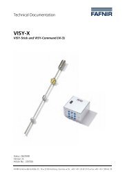
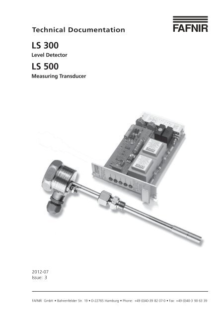
Technical Documentation<br />
<strong>LS</strong> <strong>300</strong><br />
Level Detector<br />
<strong>LS</strong> <strong>500</strong><br />
Measuring Transducer<br />
2012-07<br />
Issue: 3<br />
<strong>FAFNIR</strong> GmbH • Bahrenfelder Str. 19 • D-22765 Hamburg • Phone: +49 (0)40-39 82 07-0 • Fax: +49 (0)40-3 90 63 39
Table of contents<br />
Page 2/33<br />
Features of level detector type <strong>LS</strong> <strong>300</strong> . with measuring transducer <strong>LS</strong> <strong>500</strong> . ..4<br />
Safety instructions ................................................................................................5<br />
Structure and function..........................................................................................7<br />
1 Level detector type <strong>LS</strong> <strong>300</strong> . .................................................................................... 7<br />
2 Measuring transducer type <strong>LS</strong> <strong>500</strong> . ..................................................................... 14<br />
Installation ...........................................................................................................17<br />
Periodic testing....................................................................................................21<br />
1 Level detector without test connection............................................................... 21<br />
2 Level detector with test connection .................................................................... 22<br />
Level detector with measuring transducer <strong>LS</strong> <strong>500</strong> 19” AK5.............................23<br />
Fault diagnosis ....................................................................................................24<br />
1 Level detector <strong>LS</strong> <strong>300</strong> …........................................................................................ 24<br />
2 Measuring transducers <strong>LS</strong> <strong>500</strong>/Z, <strong>LS</strong> <strong>500</strong> 19"/Z and <strong>LS</strong> <strong>500</strong> 19" Duo .................. 24<br />
3 Measuring transducers <strong>LS</strong> <strong>500</strong> S, <strong>LS</strong> <strong>500</strong> 19" S ..................................................... 24<br />
4 Measuring transducer <strong>LS</strong> <strong>500</strong> 19" AK5 ................................................................ 24<br />
Technical data......................................................................................................25<br />
1 Level detector type <strong>LS</strong> <strong>300</strong> .................................................................................... 25<br />
2 Measuring transducer <strong>LS</strong> <strong>500</strong> ............................................................................... 26<br />
Type <strong>LS</strong> <strong>300</strong> and <strong>LS</strong> <strong>500</strong>
Annex ...................................................................................................................27<br />
Setting instructions .............................................................................................27<br />
1 General .................................................................................................................. 27<br />
2 Determination of after-flow quantity after response from the safety system . 27<br />
3 Establishing the threshold height for the system ............................................... 27<br />
EC type test certificate for level detector type <strong>LS</strong> <strong>300</strong> ….................................29<br />
EC type test certificate for measuring transducer type <strong>LS</strong> <strong>500</strong> … ...................31<br />
© Copyright:<br />
Reproduction and translation only with the written consent of the <strong>FAFNIR</strong> company.<br />
<strong>FAFNIR</strong> reserves the right to carry out product alterations without prior notice.<br />
Type <strong>LS</strong> <strong>300</strong> and <strong>LS</strong> <strong>500</strong> Page 3/33
Features of level detector type <strong>LS</strong> <strong>300</strong> . with measuring<br />
transducer <strong>LS</strong> <strong>500</strong> .<br />
Page 4/33<br />
Level detector type <strong>LS</strong> <strong>300</strong> with measuring transducer <strong>LS</strong> <strong>500</strong> constitutes a safety<br />
system which is designed to prevent the overfilling of tanks and process vessels<br />
by subjecting them to constant monitoring.<br />
The safety system can be used in all storage tanks containing liquids. It consists<br />
of a level detector in the tank and a measuring transducer with output terminal<br />
for wall installation or for fitting in the 19” system.<br />
The level detector can easily be customised to suit the respective size of tank. The<br />
safety system is maintenance-free.<br />
Type <strong>LS</strong> <strong>300</strong> and <strong>LS</strong> <strong>500</strong>
Safety instructions<br />
Level detector type <strong>LS</strong> <strong>300</strong> . with measuring transducer <strong>LS</strong> <strong>500</strong> . is used for<br />
monitoring liquids in tanks and process vessels. Use the devices for this purpose<br />
only. The manufacturer shall not be liable for any form of damage resulting from<br />
improper use!<br />
Level detector type <strong>LS</strong> <strong>300</strong> . with measuring transducer <strong>LS</strong> <strong>500</strong> . was developed,<br />
manufactured and inspected in accordance with state-of-the-art technology and<br />
recognised technical safety rules and regulations. Nevertheless, hazards may<br />
arise from the use of it. Therefore, please observe the following safety instructions:<br />
• Do not change or modify the system or add any equipment without the prior<br />
consent of the manufacturer.<br />
• The installation, operation and maintenance of the system may only be carried<br />
out by expert, authorised personnel. Only experienced electricians are allowed<br />
to install and service the system. Specialized knowledge must be obtained by<br />
undergoing regular training.<br />
• Operators, installers and service personnel must observe all applicable safety<br />
regulations. This also applies to the local safety regulations and accident<br />
prevention regulations not mentioned in these operating instructions.<br />
• During installation of the level detector the sensor may only be in an intensive<br />
vapour flow if it is provided with a protective sleeve to prevent excessive<br />
vapour movement.<br />
• The measuring transducer may not be operated in potentially explosive<br />
atmospheres and must be installed in enclosed rooms or in a housing conforming<br />
to protection class IP 54.<br />
• The plug-in printed circuit board version of measuring transducer type<br />
<strong>LS</strong> <strong>500</strong> . 19” must be installed in a housing with protection of at least IP 20.<br />
• Following the installation work and when changing the storage liquid, an<br />
inspection with respect to determining proper installation and perfect operation<br />
must be carried out by an expert of the specialised company or the operator.<br />
• Electric circuits for horns and lamps that cannot be switched according to the<br />
quiescent current principle must be easy to check with respect to their<br />
operability.<br />
• Prior to putting into service, all the devices of the overflow prevention must<br />
be checked with respect to correct connection and proper operation. The<br />
electrical power supply, including the supply of the downstream devices, must<br />
be checked.<br />
Type <strong>LS</strong> <strong>300</strong> and <strong>LS</strong> <strong>500</strong> Page 5/33
Page 6/33<br />
• The specialised company or operator of the system may only use such system<br />
parts without inspection symbols that comply with the national regulations.<br />
• In case of failure of the auxiliary power supply (exceeding or dropping below<br />
the limit values) or in case of interruption of the connecting lines between the<br />
system parts, level detector type <strong>LS</strong> <strong>300</strong> . with measuring transducer <strong>LS</strong> <strong>500</strong> .<br />
must report this fault or indicate the maximum filling level.<br />
The safety instructions in this manual are labelled as follows:<br />
If you fail to observe these safety instructions, there is a risk of an<br />
accident or the level detector type <strong>LS</strong> <strong>300</strong> . or measuring transducer<br />
<strong>LS</strong> <strong>500</strong> . may be damaged.<br />
Useful information that will guarantee proper functioning of the<br />
devices or facilitate your work.<br />
Type <strong>LS</strong> <strong>300</strong> and <strong>LS</strong> <strong>500</strong>
Structure and function<br />
1 Level detector type <strong>LS</strong> <strong>300</strong> .<br />
The level detector consists of a sensor (encapsulated PTC resistor) and a probe<br />
tube which can be adjusted in height with a clampable screw-in unit is permanently<br />
mounted using a flange (see figs. 2a–d and chap. "Installation").<br />
The encapsulated PTC resistor serves for detecting the liquid level. Detecting the<br />
liquid level is the purpose of the encapsulated PTC resistor in the form of a varying<br />
resistance at the threshold point of the level detector, the resistance value of<br />
which increases with rising temperature (see figs. 2a–2d).<br />
Since liquids possess better heat conductivity values than gases, the PTC resistor<br />
heats up in air or gas spaces. In case of submergence of the PTC resistor in liquid,<br />
e.g. upon reaching the liquid level, the PTC-resistor cools off and the resistance<br />
value drops. The signal current is limited in such a way that a re-heating of the<br />
PTC resistor in its submerged state is not possible. In a gaseous environment, the<br />
heating-up time of the PTC resistor ranges from 15 seconds (at +60 °C ambient<br />
temperature) to two minutes (at -20 °C ambient temperature).<br />
1.1 Level detector type <strong>LS</strong> <strong>300</strong> . SP ..<br />
This type of level detector is fitted with a pneumatic testing unit and a test<br />
connection on the probe tube (see figs. 2b–d). This testing unit is connected to an<br />
external pressure supply for performing the function test (e.g. the portable tester<br />
type FS 82 T).<br />
The tester type FS 82 T is available from the <strong>FAFNIR</strong> company as an<br />
optional extra.<br />
The gas required for the function test (e.g. nitrogen) is fed directly by the testing<br />
unit to the PTC resistor sensor. During the diffusion process the PTC resistor is<br />
cooled by the gas flow to the value that is equivalent to immersion in a liquid. The<br />
signal display installed is activated and operability of the overfill prevention is<br />
indicated.<br />
Type <strong>LS</strong> <strong>300</strong> and <strong>LS</strong> <strong>500</strong> Page 7/33
1.2 Type code<br />
There are various versions of level detector type <strong>LS</strong> <strong>300</strong> . available (see figs. 2a–2d):<br />
As an optional feature the sensor tip can be supplied in tantalum and parts<br />
coming into contact with the product can be made of the materials listed in the<br />
section "Materials" or they can be coated additionally with E-CTFE (Halar) (B). All<br />
level detectors can also be supplied for -25 °C to +80 °C liquid temperature (H).<br />
A non-return valve (R) is compulsory if the pneumatic test pipe is laid permanently.<br />
Page 8/33<br />
When being used in a potentially explosive atmosphere the special<br />
conditions in the EC type test certificate must be observed.<br />
Type designation Figure Probe tube [mm] Min. connection dimensions<br />
<strong>LS</strong> <strong>300</strong> E Fig. 2a Ø 10 x 1,5 G 3/8<br />
<strong>LS</strong> <strong>300</strong> ES Fig. 2a Ø 24 x 2 G 1<br />
<strong>LS</strong> <strong>300</strong> F Fig. 2a Ø 10 x 1,5 DN 15<br />
<strong>LS</strong> <strong>300</strong> FS Fig. 2b Ø 24 x 2* DN 25<br />
<strong>LS</strong> <strong>300</strong> F Duo Fig. 2b Ø 10 x 1,5 DN 25<br />
<strong>LS</strong> <strong>300</strong> E SP Fig. 2b Ø 24 x 2 G 1<br />
<strong>LS</strong> <strong>300</strong> F SP Fig. 2c Ø 24 x 2* DN 25<br />
<strong>LS</strong> <strong>300</strong> F SP Plug-in Fig. 2c Ø 24 x 2* DN 25<br />
<strong>LS</strong> <strong>300</strong> E SP Plug-in Fig. 2c Ø 24 x 2 G 1<br />
<strong>LS</strong> <strong>300</strong> F Duo Plug-in Fig. 2d Ø 10 x 1,5 DN 25<br />
* E-CTFE (Halar) coated<br />
Explanation of type codes<br />
E = screw-in unit<br />
F = flange<br />
Duo = 2 level detectors in one flange<br />
S = Probe tube Ø 24 x 2<br />
P = Pneumatic test connection (function test)<br />
Plug-in = Pluggable electrical connection (counter plug S-28 is not included in the<br />
scope of delivery)<br />
R = Non-return valve<br />
U = Overvoltage protection integrated<br />
H = Special temperature range -25 to +80 °C<br />
In the case of the level detectors provided with a clampable screw-in unit (G 1 or<br />
G 3/8) the individual threshold length for the respective tank can be adjusted by<br />
moving the probe tube in the screw-in unit (see figs. 2a–d and chap. "Installation").<br />
In the case of the level detectors provided with a flange the probe tube is<br />
permanently installed and its height is not adjustable.<br />
Type <strong>LS</strong> <strong>300</strong> and <strong>LS</strong> <strong>500</strong>
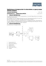
1.3 Examples of configurations<br />
88<br />
90<br />
55 (SW 51)<br />
SW 17<br />
max. torque<br />
3 Nm<br />
90<br />
55 (SW 51)<br />
Cable entry<br />
PG 11<br />
Earth connector<br />
SW 10<br />
60<br />
95<br />
Cable entry<br />
PG 11<br />
135<br />
Cable entry<br />
PG 11<br />
Earth connector<br />
SW 10<br />
Earth connector<br />
SW 10<br />
Threshold length<br />
permanently<br />
imprinted<br />
Probe length<br />
permanently<br />
imprinted<br />
Flange acc. to<br />
DIN or ASA<br />
connection dimensions<br />
acc. to DIN 2501,<br />
excluded<br />
designs L and M<br />
or equivalent<br />
foreign standards<br />
Probe length<br />
permanently<br />
imprinted<br />
Hexagon socket head screw<br />
SW 5<br />
tightening torque<br />
8 Nm<br />
SW 22<br />
Probe length<br />
Threshold length (max. <strong>300</strong>0 mm) 35<br />
12<br />
Fig. 2a: Level detectors type <strong>LS</strong> <strong>300</strong> E, type <strong>LS</strong> <strong>300</strong> E S and type <strong>LS</strong> <strong>300</strong> F<br />
Type <strong>LS</strong> <strong>300</strong> and <strong>LS</strong> <strong>500</strong> Page 9/33<br />
+2<br />
50<br />
G 3/8<br />
SW 41<br />
18<br />
G1<br />
Threshold length (max. <strong>300</strong>0 mm)<br />
Probe length<br />
Ø10<br />
Threshold length (max. <strong>300</strong>0 mm)<br />
Ø24<br />
Ø12<br />
Threshold point<br />
Ø12<br />
Threshold point<br />
24<br />
Threshold point<br />
24<br />
Ø24<br />
24
Page 10/33<br />
SW 17<br />
max. torque<br />
3 Nm<br />
88<br />
SW 17<br />
max. torque<br />
3 Nm<br />
88<br />
SW 17<br />
max. torque<br />
3 Nm<br />
88<br />
Earth connector<br />
SW 10<br />
Earth connector<br />
SW 10<br />
Earth connector<br />
SW 10<br />
155<br />
Cable entry<br />
PG 11<br />
135<br />
Cable entry<br />
PG 11 (2x)<br />
Cable entry<br />
PG 11<br />
155<br />
Ball cock<br />
Test connection<br />
Threshold length<br />
permanently<br />
imprinted<br />
Probe length<br />
permanently<br />
imprinted<br />
Hexagon socket head screw<br />
SW 5<br />
tightening torque<br />
8 Nm<br />
50<br />
+2<br />
Flange acc. to<br />
DIN or ASA<br />
connection<br />
dimensions acc.<br />
to DIN 2501,<br />
excluded<br />
designs L and M<br />
or equivalent<br />
foreign standards<br />
Threshold length<br />
permanently<br />
imprinted<br />
SW 41<br />
18<br />
G1<br />
Threshold length (max. <strong>300</strong>0 mm)<br />
Probe length<br />
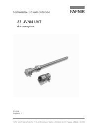
Threshold point 1<br />
(overfill prevention)<br />
Threshold length 2 (max. <strong>300</strong>0 mm)<br />
Threshold length 1<br />
Flange acc. to<br />
DIN or ASA<br />
connection<br />
dimensions acc.<br />
to DIN 2501,<br />
excluded<br />
designs L and M<br />
or equivalent<br />
foreign standards<br />
Threshold point 2<br />
Threshold length (max. <strong>300</strong>0 mm)<br />
Fig. 2b: Level detectors type <strong>LS</strong> <strong>300</strong> F S, type <strong>LS</strong> <strong>300</strong> F Duo and type <strong>LS</strong> <strong>300</strong> E SP<br />
Threshold point<br />
Threshold point<br />
24<br />
24<br />
24<br />
Ø24<br />
Ø12<br />
Ø24<br />
Type <strong>LS</strong> <strong>300</strong> and <strong>LS</strong> <strong>500</strong>
115<br />
88<br />
SW 17<br />
max. torque 3 Nm<br />
115<br />
88 SW 17<br />
max. torque 3 Nm<br />
SW 17<br />
max. torque<br />
3 Nm<br />
88<br />
Junction box<br />
type DD 28<br />
pin assignment<br />
1 and 6<br />
for plug<br />
type S 28<br />
Earth connector<br />
SW 10<br />
135<br />
Junction box<br />
type DD 28<br />
pin assignment<br />
1 and 6<br />
for plug<br />
type 28<br />
155<br />
155<br />
Ball cock<br />
Ball cock<br />
Cable entry<br />
PG 11<br />
Ball cock<br />
Earth connector<br />
Test connection<br />
Probe length<br />
permanently<br />
imprinted<br />
hexagon socket head screw<br />
SW 5<br />
tightening torque<br />
8 Nm<br />
Earth connector<br />
SW 10<br />
Test connection<br />
Test connection<br />
Threshold length<br />
permanently<br />
imprinted<br />
Threshold length<br />
permanently<br />
imprinted<br />
Probe length<br />
Flange acc. to<br />
DIN or ASA<br />
connection<br />
dimensions acc.<br />
to DIN 2501,<br />
excluded<br />
designs L and M<br />
or equivalent<br />
foreign standards<br />
Threshold length (max. <strong>300</strong>0 mm)<br />
Flange acc. to<br />
DIN or ASA<br />
connection<br />
dimensions acc.<br />
to DIN 2501,<br />
excluded<br />
designs L and M<br />
or equivalent<br />
foreign standards<br />
Threshold length (max. <strong>300</strong>0 mm)<br />
Type <strong>LS</strong> <strong>300</strong> and <strong>LS</strong> <strong>500</strong> Page 11/33<br />
50<br />
+2<br />
18<br />
SW 41<br />
G 1<br />
Threshold length (max. <strong>300</strong>0 mm)<br />
Fig. 2c: Level detectors type <strong>LS</strong> <strong>300</strong> F SP, <strong>LS</strong> <strong>300</strong> F SP plug-in and type <strong>LS</strong> <strong>300</strong> E SP plug-in<br />
Threshold point<br />
Threshold point<br />
Threshold point<br />
24<br />
24<br />
24<br />
Ø24<br />
Ø24<br />
Ø24
Page 12/33<br />
Threshold length 2 (max. <strong>300</strong>0 mm) 125<br />
Threshold length (max. <strong>300</strong>0 mm)<br />
24<br />
Ø12<br />
Junction box<br />
type DD 28<br />
pin assignment<br />
1 and 6 for sensors 1<br />
3 and 4 for sensors 1<br />
Threshold lengths<br />
permanently<br />
imprinted<br />
Flange acc. to<br />
DIN or ASA<br />
connection dimensions<br />
acc. to DIN 2501<br />
excluded<br />
designs L and M<br />
or equivalent<br />
foreign standards<br />
Threshold point 1<br />
(overfill prevention)<br />
Threshold point 2<br />
Fig. 2d: Level detector <strong>LS</strong> <strong>300</strong> F Duo Plug-in<br />
1.4 All parts coming into contact with media are made of material 316 Ti, Hastelloy C<br />
or B. Flanges are also available made of steel with clad sealing surfaces made of<br />
material 316 Ti, Hastelloy C or B.<br />
Parts coming into contact with<br />
media are made of<br />
Material e.g. 316 Ti<br />
Material Hastelloy B or C<br />
Tantalum (sensor tip) and stainless steel<br />
with E-CTFE coating<br />
Tantalum (sensor tip) and stainless steel<br />
Tantalum<br />
Stainless steel<br />
Stainless steel<br />
Tantalum and Halar<br />
Tantalum and stainless steel<br />
Tantalum<br />
Type <strong>LS</strong> <strong>300</strong> and <strong>LS</strong> <strong>500</strong>
1.5 Application<br />
Level detector type <strong>LS</strong> <strong>300</strong> . is operated under the below mentioned conditions<br />
in tanks for the storage of combustible and non-combustible, water-endangering<br />
liquids from which no permanent deposits are to be expected.<br />
• Ambient conditions<br />
Temperature: -20 °C to +60 °C<br />
Pressure: 0.8 bar to 1.1 bar<br />
• Deviating conditions<br />
Liquid temperature<br />
Normal temperature: -25 °C to +50 °C<br />
Special temperature: -25 °C to +80 °C<br />
Pressure<br />
Standard pressure range: 0 to 4 bar<br />
Special version: 0 to 26 bar<br />
Deviations, e.g. 0 °C to +80 °C, stated on the rating plate.<br />
If the sensor tip cools down on account of substantial liquid spraying<br />
or vapour movement, the level detector will switch off prematurely.<br />
This can be avoided by fitting a protective sensor sleeve against<br />
excessive vapour movement.<br />
Type <strong>LS</strong> <strong>300</strong> and <strong>LS</strong> <strong>500</strong> Page 13/33
2 Measuring transducer type <strong>LS</strong> <strong>500</strong> .<br />
Page 14/33<br />
The measuring transducer consists of evaluation electronics for the PTC resistor of<br />
the level detector, potential-free changeover contacts for connecting to a control<br />
system or a power factor as well as signal lamps inside the housing.<br />
The evaluation electronic converts the resistance changes at the PTC resistor to<br />
relay operations with a binary signal output. Operation of the PTC resistor is<br />
constantly monitored by the scanner integrated into the measuring transducer.<br />
The properties of the PTC resistor, e.g. heating up and cooling down behaviour,<br />
are checked several times a second without affecting the running measuring<br />
process. The test function ensures that the PTC resistors which are no longer<br />
operationally reliable on account of external influences (corroded sensor sleeve)<br />
are detected immediately and reported owing to a response from the alarm<br />
system of the overfill prevention. Since the power fed to the PTC resistor via the<br />
scanner is regulated accurately, maximum operational reliability and service life<br />
are guaranteed.<br />
The state of electrical readiness for operation of the measuring transducer is<br />
indicated by the green pilot lamp on the front of the device. The blue (red) signal<br />
lamp flashes if the PTC resistor is in the heated state (scanner function).<br />
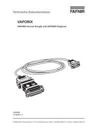
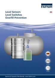
2.1 Measuring transducer type <strong>LS</strong> <strong>500</strong> .<br />
A relay release occurs if the tip of the level detector cools down and in the event<br />
of a fault (detection by the scanner), power failure, short circuit and cable<br />
breakage in the connection between the level detector and the measuring<br />
transducer. This is indicated by the yellow LED going out (see fig. 3b).<br />
With the exception of type <strong>LS</strong> <strong>500</strong> Duo, there is an alarm relay with an<br />
LED available as an option. If there is an interruption or a short circuit<br />
in the signal line between the level detector and the measuring<br />
transducer, the relay attracts and the "Fault" LED lights up.<br />
2.2 Measuring transducer type <strong>LS</strong> <strong>500</strong> 19" AK5<br />
A flashing blue LED on the device indicates that the PTC resistor is heated up<br />
(scanner function). In this state the relay contact for controllers and indicators is<br />
closed. When the level detector tip has cooled down and in the event of<br />
malfunctions (detection by the scanner), short circuit or cable breakage in the<br />
connection between the level detector and the measuring transducer and in the<br />
event of an interruption in auxiliary power this relay contact is open. If a fault is<br />
detected by the monitoring electronics, this relay contact is also open and a relay<br />
contact (fault) is closed in addition.<br />
Type <strong>LS</strong> <strong>300</strong> and <strong>LS</strong> <strong>500</strong>
150<br />
Sensor<br />
Scanner<br />
#Fault<br />
Power<br />
75<br />
Type <strong>LS</strong> <strong>300</strong> and <strong>LS</strong> <strong>500</strong> Page 15/33<br />
110<br />
Fig. 3a: Measuring transducer type <strong>LS</strong> <strong>500</strong><br />
7 TE 7 TE<br />
Power<br />
Power<br />
Sensor<br />
Sensor 1<br />
Scanner Scanner 1<br />
Fault<br />
Sensor 2<br />
Scanner 2<br />
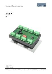
<strong>LS</strong> <strong>500</strong> 19" <strong>LS</strong> <strong>500</strong> 19" DUO<br />
Device ready for operation<br />
LED lights green<br />
Filling process can be started<br />
LED lights yellow<br />
Scanner function<br />
LED flashes blue (red)<br />
Fig. 3b: Measuring transducer type <strong>LS</strong> <strong>500</strong> 19", type <strong>LS</strong> <strong>500</strong> 19" Duo and <strong>LS</strong> <strong>500</strong> AK5
2.3 Type code<br />
There are three basic versions of measuring transducers available (type <strong>LS</strong> <strong>500</strong> /<br />
<strong>LS</strong> <strong>500</strong> 19" / <strong>LS</strong> <strong>500</strong> 19" Duo) (see figs. 3a and 3b). Types <strong>LS</strong> <strong>500</strong> and <strong>LS</strong> <strong>500</strong> 19" are<br />
also available with additional alarm (S). An alarm is no longer possible if two<br />
potential-free change-over contacts are available for alarm signalling (Z). Type <strong>LS</strong><br />
<strong>500</strong> 19" AK5 can only be supplied in 24 V (AC/DC) whereas all the other types can<br />
be supplied with 24 V, 110 V, 230 V, 40...60 Hz and 24 V:<br />
Page 16/33<br />
Type designation Figures<br />
<strong>LS</strong> <strong>500</strong> Fig. 3a<br />
<strong>LS</strong> <strong>500</strong> S<br />
<strong>LS</strong> <strong>500</strong> Z<br />
<strong>LS</strong> <strong>500</strong> 19“ Fig. 3b<br />
<strong>LS</strong> <strong>500</strong> 19“ S<br />
<strong>LS</strong> <strong>500</strong> 19“ Z<br />
<strong>LS</strong> <strong>500</strong> 19“ AK 5<br />
<strong>LS</strong> <strong>500</strong> 19“ Duo Fig. 3b<br />
Explanation of type codes<br />
S = Additional alarm<br />
Z = 2 potential-free change-over contacts for alarm signalling<br />
Duo = Evaluation of two level detectors<br />
Type <strong>LS</strong> <strong>300</strong> and <strong>LS</strong> <strong>500</strong>
Installation<br />
For all work performed on the level detector type <strong>LS</strong> <strong>300</strong> . and<br />
measuring transducer <strong>LS</strong> <strong>500</strong> ., observe the national safety and<br />
accident prevention regulations as well as all the safety instructions<br />
in this manual of operating instructions.<br />
To set up and operate the system, the generally recognised rules of<br />
engineering and these operating instructions are applicable.<br />
During installation of the level detector the sensor may only be in an<br />
intensive vapour flow if it is provided with a protective sleeve against<br />
excessive vapour movement.<br />
The measuring transducer may not be operated in potentially explosive<br />
atmospheres and must be installed in enclosed rooms or in a<br />
housing conforming to protection class IP 54.<br />
The installation position of the level detector in the tank must be selected so that<br />
neither splashes of liquid nor excessive vapour flow can result in premature<br />
response of the system or faults. The level detector should be installed as<br />
vertically as possible so that any residual liquid can drop down from the sensor.<br />
Measuring transducer type <strong>LS</strong> <strong>500</strong> . must be protected against splashes<br />
of water and be installed in accordance with IP 40 housing protection.<br />
The plug-in printed circuit board version of measuring transducer<br />
type <strong>LS</strong> <strong>500</strong> 19” must be installed in a housing with protection of at<br />
least IP 20.<br />
The level detector consists of a probe tube adjustable in height which projects<br />
into the storage tank and possesses a sensor at the bottom end protected against<br />
physical damage. Each probe length (Z) is permanently imprinted at the top end<br />
of the probe, above the marking groove. The probe length is provided as a<br />
distance dimension between this marking groove and the threshold point of the<br />
level detector.<br />
In order to adjust the threshold length (L) as a distance between the hexagon<br />
support of the screw-in unit and the marking groove on the protective sleeve of<br />
the sensor at the bottom end of the level detector, proceed as follows:<br />
• Calculate the threshold length (L) depending on the tank dimensions and the<br />
threshold height (A). L = (H – A) + S<br />
• Adjust the calculated threshold length (L) on the level detector.<br />
Type <strong>LS</strong> <strong>300</strong> and <strong>LS</strong> <strong>500</strong> Page 17/33
Page 18/33<br />
When the level detector has been installed, the correct adjustment of<br />
the threshold length (L) can be checked, without removing the sensor,<br />
by means of the reference dimension (Y) (= distance between the<br />
marking groove at the top end of the probe tube and the hexagon<br />
support of the screw-in unit) and the imprinted probe length (Z).<br />
L=Z – Y<br />
In order to lock the probe tube in place, proceed as follows:<br />
• Tighten the upper gland screw and the locking screw of the screw-in unit<br />
firmly.<br />
• Provide the screw-in thread with suitable, resistant sealing material and screw<br />
it into the tank muff provided for it.<br />
Since the threshold length (L) of level detector type <strong>LS</strong> <strong>300</strong> F.. is not<br />
variable (probe tube welded into the flange), this dimension must be<br />
calculated and specified before order placement using the tank<br />
dimensions and the accurately determined threshold length (A). The<br />
threshold length is permanently imprinted in the flange of the level<br />
detector.<br />
Wiring work may only be carried out when the equipment is<br />
disconnected from the mains.<br />
The wiring between the level detector and the measuring transducer must be<br />
carried out using a blue cable or a cable marked blue. The cable length must not<br />
exceed 250 m for a cross-section of 0.5 mm2 , <strong>500</strong> m for 1 mm2 and 750 for 1.5 mm2 .<br />
In the event of different cross-sections the maximum length of cable will also be<br />
different.<br />
The measuring transducer is suitable for wall mounting, control cabinet installation<br />
and fitting in 19" systems.<br />
For the connections required for installation of the relevant measuring transducer<br />
please refer to the wiring diagrams in fig. 4.<br />
If the measuring transducer is set up in the field, the housing protection<br />
type must be at least IP 54. For use of the level detector within<br />
potentially explosive atmospheres in tanks outside buildings,<br />
overvoltage protection must be provided in the signal sensor line.<br />
Only if the signal sensor line is laid in a metal tube or metal cable<br />
conduit (the pipe or conduit must be connected to tank potential or be<br />
integrated into the equipotential bonding system) is it possible to<br />
dispense with overvoltage protection. Level detector types <strong>LS</strong> <strong>300</strong>...U<br />
are provided with integrated voltage protection.<br />
Type <strong>LS</strong> <strong>300</strong> and <strong>LS</strong> <strong>500</strong>
If there is no overvoltage protection, the overvoltage protection type<br />
BA 350 must be fitted close to the level detector (approx. 50 cm). An<br />
external earthing terminal is provided for the electrical connection<br />
(4 mm 2 cable) between the housing and the tank.<br />
Prior to putting into service, all the devices in the system must be<br />
checked with respect to correct connection and proper operation. In<br />
addition, the electrical power supply, including that of the downstream<br />
devices, must also be checked. For this purpose observe the relevant<br />
operating instructions for the devices being used.<br />
Type <strong>LS</strong> <strong>300</strong> and <strong>LS</strong> <strong>500</strong> Page 19/33
Page 20/33<br />
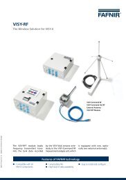
<strong>LS</strong> <strong>500</strong><br />
Level detector<br />
Output<br />
level detector<br />
Output<br />
"S" or "Z"<br />
(option)<br />
Auxiliary power<br />
24, 110, 230 V, 50 Hz<br />
24 V DC<br />
<strong>LS</strong> <strong>500</strong> 19" <strong>LS</strong> <strong>500</strong> 19" Duo<br />
Level detector<br />
Output<br />
level detector<br />
Output<br />
"S" or "Z"<br />
(option)<br />
Auxiliary power<br />
24, 110, 230 V, 50 Hz<br />
24 V DC<br />
PE<br />
L1 (+)<br />
N (-)<br />
d z<br />
02<br />
04<br />
06<br />
08<br />
10<br />
12<br />
14<br />
16<br />
18<br />
20<br />
22<br />
24<br />
26<br />
28<br />
30<br />
32<br />
<strong>LS</strong> <strong>500</strong> 19" AK5<br />
Level detector<br />
Output<br />
level detector 1<br />
Output<br />
fault<br />
Auxiliary power<br />
24, 110, 230 V, 50 Hz<br />
24 V DC<br />
Level detector<br />
PE<br />
L1 (+)<br />
01<br />
02<br />
06<br />
07<br />
08<br />
09<br />
09<br />
10<br />
11<br />
12<br />
13<br />
14<br />
15<br />
Fig. 4: Wiring diagram – measuring transducer<br />
N (-)<br />
1<br />
2<br />
Output<br />
level detector 1<br />
Output<br />
level detector 2<br />
Auxiliary power<br />
24, 110, 230 V, 50 Hz<br />
24 V DC<br />
PE<br />
L1 (+)<br />
N (-)<br />
d z<br />
02<br />
04<br />
06<br />
08<br />
10<br />
12<br />
14<br />
16<br />
18<br />
20<br />
22<br />
24<br />
26<br />
28<br />
30<br />
32<br />
PE<br />
L1 (+)<br />
N (-)<br />
d z<br />
02<br />
04<br />
06<br />
08<br />
10<br />
12<br />
14<br />
16<br />
18<br />
20<br />
22<br />
24<br />
26<br />
28<br />
30<br />
32<br />
Type <strong>LS</strong> <strong>300</strong> and <strong>LS</strong> <strong>500</strong>
Periodic testing<br />
The performance of the level detector/measuring transformer must<br />
be tested at reasonable intervals, but at least once a year. It is the<br />
operator's responsibility to select the method of testing and the<br />
intervals within the specified period.<br />
Testing must be performed in such a way that it verifies correct performance<br />
when all the components in the system interact with one another.<br />
This interaction takes place when approaching the threshold height during<br />
filling. If filling up to the threshold height is not practicable, the level detector<br />
must be made to respond by suitable simulation of the level of liquid or of the<br />
physical measuring effect.<br />
If the performance of the level detector/measuring transducer can be established<br />
in another way (exclusion of function-retarding faults), the test can also be<br />
performed by simulating the relevant output signal.<br />
1 Level detector without test connection<br />
If the level detector does not have a test connection (see type code in chap.<br />
"Structure and mode of operation") with a measuring transformer you can<br />
conduct the function test as follows:<br />
• Remove the level detector and immerse it in the storage liquid; approx. two<br />
seconds after immersion of the level detector the relay in the measuring<br />
transducer should release and thus activate the signalling unit.<br />
• Fill tank up to the threshold height (see chap. "Installation"); the system<br />
should respond and activate the signalling unit.<br />
1.1 Take the quiescent current principle of the signalling unit<br />
In order to check whether the signalling unit is operating according to the<br />
quiescent current principle, either<br />
• interrupt the auxiliary power supply to the measuring transducer (the green<br />
LED on the device must no longer be lit) or<br />
• interrupt or short-circuit the signal line between the level detector and the<br />
measuring transducer.<br />
In both cases the signalling unit should respond.<br />
Type <strong>LS</strong> <strong>300</strong> and <strong>LS</strong> <strong>500</strong> Page 21/33
2 Level detector with test connection<br />
Page 22/33<br />
If the level detector has a test connection (see type code in chap. "Structure and<br />
mode of operation") with a measuring transformer the function test must first<br />
of all be prepared. Then an external pressurised gas unit must be connected to<br />
the test connection integrated into the level detector (e.g. the type FS 82 T<br />
portable tester optionally available from the <strong>FAFNIR</strong> company):<br />
• Connect the pressurised gas unit to the pneumatic test connection using a<br />
push-fit coupling or threaded connection (with non-return valve) (see fig. 5).<br />
• For the purpose of additional protection from the tank open the ball cock<br />
located behind the push-fit coupling or the non-return valve (see Fig. 5). Now<br />
the gas can be fed to the PTC resistor via the test connection. The PTC resistor<br />
thus cools down to the value equivalent to immersion of the PTC resistor in<br />
liquid.<br />
In order to verify performance the signalling unit must respond.<br />
135<br />
50<br />
Probe length<br />
Threshold length max <strong>300</strong>0 mm)<br />
18<br />
24<br />
88<br />
Ø24<br />
SW 17<br />
max. torque<br />
3 Nm<br />
Earth connector<br />
SW 10<br />
Cable entry<br />
PG 11<br />
Ball cock<br />
Test connection<br />
Probe length<br />
permanently<br />
imprinted<br />
Hexagon socket head screw<br />
SW 5<br />
tightening torque<br />
+2<br />
8 Nm<br />
SW 41<br />
Threshold point<br />
Fig. 5: Level detector type <strong>LS</strong> <strong>300</strong> E SP<br />
G1<br />
Type <strong>LS</strong> <strong>300</strong> and <strong>LS</strong> <strong>500</strong>
3 Level detector with measuring transducer <strong>LS</strong> <strong>500</strong> 19” AK5<br />
Level detectors with measuring transducer <strong>LS</strong> <strong>500</strong> 19” AK5 are subject to constant<br />
self-monitoring. Owing to failsafe operation it is possible to dispense with the<br />
periodic performance test on the overfill prevention.<br />
Downstream parts of equipment such as alarm and fault indicating units are<br />
checked by pressing buttons on the measuring transducer:<br />
• Check downstream alarm systems by pressing the test button "Test indicators"<br />
on the measuring transducer for 2 seconds<br />
• Check downstream fault indicating systems by pressing the test button "Test<br />
fault" on the measuring transducer for 2 seconds<br />
Type <strong>LS</strong> <strong>300</strong> and <strong>LS</strong> <strong>500</strong> Page 23/33
Fault diagnosis<br />
1 Level detector <strong>LS</strong> <strong>300</strong> …<br />
Page 24/33<br />
Corrosion monitoring is not required because the level detector is<br />
continuously tested and monitored by the measuring transducer. On the<br />
measuring transducer this procedure is indicated by the flashing blue<br />
LED "Scanner". If a fault occurs such as a short circuit or cable breakage<br />
due to corrosion, an alarm signal is given.<br />
2 Measuring transducers <strong>LS</strong> <strong>500</strong>/Z, <strong>LS</strong> <strong>500</strong> 19"/Z and<br />
<strong>LS</strong> <strong>500</strong> 19" Duo<br />
In the event of a power failure, failure of device fuses, inoperable sensor<br />
element or a short circuit in the signal line between the level detector<br />
and the measuring transducer the relay in the measuring transducer<br />
releases and operates the sequence control circuit.<br />
3 Measuring transducers <strong>LS</strong> <strong>500</strong> S, <strong>LS</strong> <strong>500</strong> 19" S<br />
In the event of an interruption or short circuit in the signal line between<br />
the level detector and the measuring transducer an alarm relay attracts<br />
and the red LED "Fault" lights up. If there is a short circuit in the signal<br />
line, the blue LED "Scanner" also lights up.<br />
4 Measuring transducer <strong>LS</strong> <strong>500</strong> 19" AK5<br />
In the event of a power failure, failure of device fuses, an inoperable<br />
sensor element or a short circuit in the signal line between the level<br />
detector and the measuring transducer the relay contact (controllers<br />
and indicators) is open and it operates the sequence control circuit. If a<br />
fault is detected by the monitoring electronics, this relay contact is also<br />
open and a relay contact (Fault) is closed in addition.<br />
If measuring transducer <strong>LS</strong> <strong>500</strong> 19” AK5 is used, there is no<br />
need to perform the periodic test.<br />
Type <strong>LS</strong> <strong>300</strong> and <strong>LS</strong> <strong>500</strong>
Technical data<br />
1 Level detector type <strong>LS</strong> <strong>300</strong><br />
Temperature range: Media<br />
-25 °C to +50 °C<br />
-40 °C to +80 °C special temperature<br />
Pressure range: 0 to 25 bar<br />
Media compatibility: Materials of parts in contact with media:<br />
stainless steel: 316 Ti (flange)<br />
Hastelloy C or B<br />
(screw-in unit, probe tube, test nozzle, sensor)<br />
Tantalum (sensor)<br />
E-CTFE (Halar)<br />
Submergence switching<br />
delay: < 2 seconds<br />
Heating-up/release time<br />
Ambient temp.: at -20 °C < 2 min, at +60 °C < 15 sec<br />
Housing protection type: IP 67<br />
Type <strong>LS</strong> <strong>300</strong> and <strong>LS</strong> <strong>500</strong> Page 25/33
2 Measuring transducer <strong>LS</strong> <strong>500</strong><br />
Page 26/33<br />
Auxiliary power:<br />
<strong>LS</strong> <strong>500</strong> 24 V, 110 V, 230 V, 40...60 Hz or<br />
24 V DC<br />
<strong>LS</strong> <strong>500</strong> 19" AK5 24 V, 40...60 Hz or 24 V DC<br />
Power input:<br />
<strong>LS</strong> <strong>500</strong> max. 4 VA or 5 W<br />
<strong>LS</strong> <strong>500</strong> 19" Duo max. 8 VA or 10 W<br />
<strong>LS</strong> <strong>500</strong> 19" AK5 max. 6 VA or 7 W<br />
Ambient temperature: -25 °C to +50 °C<br />
Housing protection type: Must be set up with at least IP 20<br />
Outputs:<br />
<strong>LS</strong> <strong>500</strong>/<strong>500</strong> 19" 1 potential-free change-over contact<br />
(level detector)<br />
Alternating voltage:<br />
≤ 250 V; ≤ 4 A, cos ϕ ≥ 0.7; max. <strong>500</strong> VA<br />
Direct voltage:<br />
≤ 250 V; ≤ 0.25 A; max. 50 W<br />
<strong>LS</strong> <strong>500</strong> S/<strong>500</strong> 19” S 1 potential-free change-over contact<br />
(level detector)<br />
1 potential-free change-over contact (Fault)<br />
Alternating voltage: See above<br />
Direct voltage: See above<br />
<strong>LS</strong> <strong>500</strong> Z/<strong>500</strong> 19” Z 2 potential-free change-over contacts<br />
(1 level detector)<br />
Alternating voltage: See above<br />
Direct voltage: See above<br />
<strong>LS</strong> <strong>500</strong> 19" Duo 2 potential-free change-over contacts<br />
(2 level detector)<br />
Alternating voltage: See above<br />
Direct voltage: See above<br />
<strong>LS</strong> <strong>500</strong> 19" AK5 1 potential-free NOC (level detector)<br />
1 potential-free NOC (Fault)<br />
Alternating voltage:<br />
≤ 60 V; ≤ 4 A, cos ϕ ≥ 0.7; max. <strong>500</strong> VA<br />
Direct voltage:<br />
≤ 60 V; ≤ 0.25 A; max. 50 W<br />
Inputs: Level detector input: two-core,<br />
independent of polarity, max. cable length 750 m<br />
for 1.5 mm 2<br />
Type <strong>LS</strong> <strong>300</strong> and <strong>LS</strong> <strong>500</strong>
Annex<br />
Setting instructions<br />
1 General<br />
To be able to adjust the system correctly the following requirements must be<br />
met:<br />
- Knowledge of the filling height which is equivalent to the permissible degree<br />
of filling (the permissible degree of filling can be calculated in accordance<br />
with the German instruction TRbF 280 No. 2.2, see 3.1),<br />
- Knowledge of the filling height change which is equivalent to the after-flow<br />
quantity to be expected<br />
2 Determination of after-flow quantity after response from the<br />
safety system<br />
2.1 Maximum volumetric flow of the feed pump<br />
Max volumetric flow can be determined either by measurement (transferring a<br />
defined quantity of liquid by pumping) or it can be read off the pump characteristic.<br />
In the case of tanks conforming to DIN 4119 the permissible volumetric flow is<br />
stated on the tank plate.<br />
2.2 Closing delay times<br />
(1) In as much as the threshold times, switching times and running times of the<br />
various system parts are not known from the relevant data sheets they must be<br />
measured.<br />
(2) If valves have to be operated manually in order to interrupt the filling process,<br />
the time between the response of the safety system and the interruption of the<br />
filling process must be estimated according to local conditions.<br />
2.3 After-flow quantity<br />
Addition of the closing delay times results in total closing delay time. Multiplication<br />
of the total closing delay time by the volumetric flow determined in accordance<br />
with 2.1 and addition of the capacity of the pipes which may also have to be<br />
emptied after the response of the overfill prevention results in the after-flow<br />
quantity.<br />
3 Establishing the threshold height for the system<br />
The after-flow quantity determined in accordance with no. 2 is subtracted from<br />
the volume of liquid which is equivalent to the permissible degree of filling. From<br />
the difference the threshold height is determined by referring to the measuring<br />
table. If there is no measuring table available and if the threshold height cannot<br />
be determined by calculation, it must be determined by gauging the capacity of<br />
the tank by litres.<br />
Type <strong>LS</strong> <strong>300</strong> and <strong>LS</strong> <strong>500</strong> Page 27/33
3.1 Calculation of response height for safety system to prevent the overfilling of<br />
tanks<br />
Operating site: ........................... Tank no.: ............... Cubic capacity: ......... [m3 ]<br />
Overfill prevention system: Manufacturer / type: <strong>FAFNIR</strong> ....................................<br />
Inspection symbol / approval symbol: ....................................................................<br />
1 Max. volumetric flow [Q ]:............................................. max [m3 /h]<br />
2 Close delay times<br />
2.1 Level detector acc. measurement / data sheet:................ [s]<br />
2.2 Switch / relay / etc.: ............................................................ [s]<br />
2.3 Feed pump, run-out time: ................................................. [s]<br />
2.4 Shutoff valve<br />
- mechanical, manually operated<br />
Alarm time / to start of closing:............................................. [s]<br />
Closing time: ............................................................................... [s]<br />
- electrically, pneumatically or hydraulically operated<br />
Closing time: ........................................................................... [s]<br />
Total closing delay time [t ]: .................................................... tot [s]<br />
3 After-flow quantity [V ] tot<br />
3.1 After-flow quantity from total closing delay time:<br />
V = Q x ................................................................... 1 max [m3 3.2 After-flow quantity from pipes:<br />
]<br />
V = x d 2 2 x L ...................................................................... [m3 ]<br />
V = V + V ....................................................................... tot 1 2 [m3 ]<br />
4 Threshold height<br />
4.1 Quantity at permissible degree of filling: ........................ [m3 ]<br />
4.2 After-flow quantity: .......................................................... [m3 Quantity at threshold height<br />
]<br />
(= difference from 4.1 and 4.2): ........................................ [m3 ]<br />
4.3 The following threshold height results from the difference:<br />
Sounding height: ............................................................... [mm]<br />
or air sounding height:...................................................... [mm]<br />
or the contents indicator reading:.................................... [mm or m3 ttot 3.600<br />
]<br />
Page 28/33<br />
Type <strong>LS</strong> <strong>300</strong> and <strong>LS</strong> <strong>500</strong>
EG- Konformitätserklärung<br />
EC- Declaration of Conformity<br />
<strong>FAFNIR</strong> GmbH<br />
Bahrenfelder Str. 19<br />
22765 Harnburg I Germany<br />
erklärt in eigener Verantwortlichkeit, dass die Produkte<br />
declare under sole responsibility that the products<br />
Messumformer mit Standaufnehmer<br />
Measuring transmitter with tank Ievel gauge<br />
<strong>LS</strong> <strong>500</strong> ... I <strong>LS</strong> <strong>300</strong> ...<br />
in Übereinstimmung mit nachfolgenden Richtlinien:<br />
in accordance with the following directives:<br />
EMV-Richtlinie; EMC Directive:<br />
Ex-Richtlinie; Ex Directive:<br />
Nur für I Only for <strong>LS</strong> <strong>500</strong> ... :<br />
200411 081EGI EC<br />
94191EGIEC<br />
Niederspannungsrichtlinie; Low valtage Directive: 20061951EGIEC<br />
nach folgenden Vorschriften (Normen) entwickelt und gefertigt wurden:<br />
has been designed and manufactured to the following specifications:<br />
200411 081EGI EC: EN 55011:2007 + A2:2007<br />
EN 61326-1:2006<br />
94191EGIEC: EN 60079-0:2009<br />
EN 60079-11:2007<br />
EN 60079-26:2007<br />
20061951EGIEC(<strong>LS</strong> <strong>500</strong> ... ): EN 61010-1:2010<br />
Die Produkte entsprechen den EMV-Anforderungen<br />
The products camplies with the EMC requirements<br />
Emission I Emission:<br />
Immission I Immission:<br />
Die Produkte entsprechen den EG-Baumusterprüfbescheinigungen<br />
The products are in conformity with EC-Type Examination Certificates<br />
<strong>FAFNIR</strong><br />
Klasse B I Class 8<br />
Grundlegende Anforderungen I<br />
Fundamental environment<br />
<strong>LS</strong> <strong>500</strong> ... : TÜV 00 ATEX 1656 X<br />
<strong>LS</strong> <strong>300</strong> ... : TÜV 00 ATEX 1641<br />
Die Prüfung erfolgte durch die benannte Stelle Nr.: 0044 (TÜV NORD CERT GmbH)<br />
The inspection was carried out by the notified body N°: 0044 (TÜV NORD CERT GmbH)<br />
Seite I Page 111<br />
Hamburg, 30.09.2011<br />
Ort, Datum I Place, Date<br />
Geschäftsführer I Managing Director: R. Albrecht<br />
<strong>FAFNIR</strong> GmbH • Bahrenfelder Str. 19 • 22765 Hamburg • Telefon: +49 I (O) 40 I 39 82 07-0 • Telefax: +49 I (O) 40 I 390 63 39
0<br />
0 " N<br />
0<br />
Cii<br />
( 13) SCHEDULE<br />
(14) EC-TYPE EXAMINATION CERTIFICATE N° TÜV 00 ATEX 1656 X<br />
(15) Description of equipment<br />
The tank Ievel gauge type <strong>LS</strong> <strong>300</strong> ... consisting of the sensor with integrated PTC resistor, the<br />
tube, the screw-in body resp. flange and the junction box is intended for the connection to the<br />
measuring transmittertype <strong>LS</strong> <strong>500</strong> ... The gauge will be erected at tanks whereby the sensorwill<br />
be placed in zone 0.<br />
A short circuit or open circuit between the Ievel detector and the transducer will be signalized.<br />
When using the associated over valtage protection the marking is:<br />
II 1/2 G EEx ia IIC T4<br />
Electrical Data<br />
Type <strong>LS</strong> <strong>300</strong> ...<br />
Signal transmitter circuit( s)<br />
Type <strong>LS</strong> <strong>300</strong> FS ... Tantal<br />
Signal transmitter circuit( s)<br />
in type of protection "lntrinsic Safety" EEx ia IIB/IIC<br />
only for the connection to associated measuring transmitter of<br />
the type <strong>LS</strong> <strong>500</strong>, <strong>LS</strong> <strong>500</strong> 19", <strong>LS</strong> <strong>500</strong> 19" Duo or <strong>LS</strong> <strong>500</strong> 19"<br />
AK5 according to EC-type Examination Certificate No.<br />
TÜV 00 ATEX 1641<br />
in type of protection "lntrinsic Safety" EEx ia IIB<br />
only for the connection to associated measuring transmitter of<br />
the type <strong>LS</strong> <strong>500</strong>, <strong>LS</strong> <strong>500</strong> 19", <strong>LS</strong> <strong>500</strong> 19" Duo or <strong>LS</strong> <strong>500</strong> 19"<br />
AK5 according to EC-type Examination Certificate No.<br />
TÜV 00 ATEX 1641<br />
The signal transmitter circuits are galvanically separated against each other and against earth.<br />
(16) Test documents are listed in the test report No. : 01 YEX 133817.<br />
(17) Special conditions for safe use<br />
1. The tank Ievel gauges of the stated types have be connected to signal transmitter circuits of<br />
the measuring transmittertype <strong>LS</strong> <strong>500</strong> ... only.<br />
2. When using the associated over valtage protection equipontial bonding is required.<br />
(18) Essential Health and Safety Requirements<br />
no additional ones<br />
page 2/2
Translation<br />
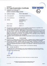
( 1) EC TYPE-EXAMINATION CERTIFICATE<br />
(2) Equipment or protective system intended for use in potentially explosive<br />
atmospheres - Directive 94/9/EC<br />
(3) EC-Type Examination Certificate Number<br />
(4) Equipment:<br />
(5) Manufacturer:<br />
(6) Address:<br />
TUV 00 ATEX 1641<br />
Measuring transmittertype <strong>LS</strong> <strong>500</strong> ...<br />
<strong>FAFNIR</strong> GmbH<br />
Bahrenfelder Strasse 19<br />
D-22765 Hamburg<br />
(7) This equipment or protective system and any acceptable variation thereto is specified in the<br />
schedule to this certificate and the documents therein referred to.<br />
(8) The TÜV Hannover/Sachsen-Anhalt e.V. , TÜV CERT-Certification Body, notified body<br />
number N° 0032 in accordance with Article 9 of the Council Directive of the EC of March 23,<br />
1994 (94/9/EC), certifies that this equipment or protective system has been found to comply<br />
with the Essential Health and Safety Requirements relating to the design and construction of<br />
equipment and protective systems intended for use in potentially explosive atmospheres<br />
given in Annex II to the Directive.<br />
The examination and test results are recorded in the confidential report N° 01YEX133809.<br />
(9) Compliance with the Essential Health and Safety Requirements has been assured by<br />
compliance with:<br />
EN 50 014: 1997 EN 50 020: 1994<br />
( 1 0) lf the sign "X" is placed after the certificate number, it indicates that the equipment or<br />
protective system is subject to special conditions for safe use specified in the schedule to<br />
this certificate.<br />
( 11) This. EC-type examination certificate relates only to the design and construction of the<br />
specified equipment or protective system according to Directive 94/9/EC. Further<br />
requirements of this Directive apply to the manufacture and placing on the market of this<br />
equipment or protective system.<br />
(12) The marking of the equipment or protective system must include the following:<br />
TÜV Hannover/Sachsen-Anhalt e.V.<br />
TÜV CERT-Zertifizierungsstelle<br />
Am TÜV 1<br />
D-30519 Hannover<br />
Head ofthe<br />
Certification Body<br />
(G II (1) G [EEx ia] IIC<br />
This certificate may only be reproduced without any change, schedule included.<br />
Excerpts or changes shall be allowed by the TÜV Hannover/Sachsen-Anhalt e.V.<br />
Hanover, 2001-03-20<br />
page 1/3
( 13) SCHEDULE<br />
(14) EC-TYPE EXAMINATION CERTIFICATE N° TÜV 00 ATEX 1641<br />
(15) Description of equipment<br />
The measuring transmitter in combination with the associated Ievei gauge type <strong>LS</strong> <strong>500</strong> ... is<br />
intended for the transmission of signals out of tanks filled with gaseaus medias resp. fluids.<br />
Electrical data<br />
Type <strong>LS</strong> <strong>500</strong>, type <strong>LS</strong> <strong>500</strong> 19", type <strong>LS</strong> <strong>500</strong> 19" Duo<br />
Supply circuit U = 24/110/230 V a.c., ± 15 %, 40 .. . 60 Hz, about 4 VA<br />
( connections d30 and d32, resp. 8 VA<br />
resp. d32 and z32 resp.<br />
resp. terminals 14 and 15) U = 24 V d.c., ± 20 %, about 5 resp. 10 W<br />
Type <strong>LS</strong> <strong>500</strong> 19" AK5<br />
Supply circuit<br />
( connections dz30 and dz32)<br />
U = 24 V a.c., 40 ... 60 Hz, about 4 VA<br />
resp.<br />
U = 24 V d.c., about 7 W<br />
Type <strong>LS</strong> <strong>500</strong>, type <strong>LS</strong> <strong>500</strong> 19", type <strong>LS</strong> <strong>500</strong> 19" Duo, type <strong>LS</strong> <strong>500</strong> 19" AK5<br />
Signal transmitter circuits in type of protection "lntrinsic Safety" EEx ia IIC<br />
(connections d2 and d4 · resp. EEx ia 118<br />
resp. d2 and z2<br />
resp . d8 and z8<br />
resp. dz2 and dz4<br />
resp. terminals 1 and 2)<br />
Maximum values: Uo = 15,8 V<br />
1 0 = 154 mA<br />
R<br />
Po<br />
= 157<br />
= 600<br />
D.<br />
mW<br />
Characteristic line: trapezoidal<br />
Ci = 1,2 nF<br />
Li negligibly small<br />
The maximum permissible value pairs of the external<br />
inductances (L 0 ) and capacitances (Co) have to be taken<br />
from the following table:<br />
EEx ia IIC EEx ia 118<br />
Lo I 0,65 mH I 1 mH 1,5 mH I 4mH<br />
Co I 200 nF I 150 nF 900 nF I 630 nF<br />
page 2/3
Translation<br />
2. 5 U P P L E M E N T<br />
to Certificate No.<br />
Equipment:<br />
Manufacturer:<br />
Address:<br />
Order number:<br />
Date of issue:<br />
Amendments:<br />
TÜV 00 ATEX 1641<br />
Measuring Transmitter type <strong>LS</strong> <strong>500</strong> ...<br />
<strong>FAFNIR</strong> GmbH<br />
Bahrenfelder Straße 19<br />
22765 Harnburg<br />
Germany<br />
8000396761<br />
2011-08-25<br />
TrN,:;;;;;:;<br />
ln the future, the Measuring Transmitter type <strong>LS</strong> <strong>500</strong> .. . may also be manufactured according to the<br />
test documents listed in the test report.<br />
The permissible ambient temperature rangewill be -25 oc to +50 oc in the future.<br />
Furthermore the "Eiectrical data" was changed.<br />
Electrical Data<br />
Type <strong>LS</strong> <strong>500</strong> ... , type <strong>LS</strong> <strong>500</strong> 19" ... , type <strong>LS</strong> <strong>500</strong> 19" Duo<br />
Supply circuit U = 24/115/230 V a.c., ±1 0 %, 40 ... 60 Hz, about 4<br />
(terminals 15 (L 1 ), 14 (N) and 12/13 (PE) resp. 8 VA<br />
resp. connections d30 (L 1 ), d32 (N) and resp.<br />
dz14/dz28 (PE) resp. d32 (L 1), z32 (N) U = 24 V d.c., ±20 %, about 5 resp. 10 W<br />
and dz16/dz30 (PE))<br />
Type <strong>LS</strong> <strong>500</strong> 19" AK5<br />
Supply circuit<br />
(connections dz30 (L), dz32 (N) resp.<br />
dz8/dz28 (PE))<br />
P17 -F-006 06-06<br />
Um = 33 V at 24 V d.c. resp. 24 V a.c.<br />
Um= 130 V at 115 V a.c.<br />
Um = 253 V at 230 V a.c.<br />
U = 24 V a.c., ±10 %, 40 ... 60 Hz, about 4 VA<br />
resp.<br />
U = 24 V d.c., ±20% about 7 W<br />
Um = 33 V at 24 V d.c. resp. 24 V a.c.<br />
page 1/3