Design Guide: CompactPCI ® PlusIO - picmg
Design Guide: CompactPCI ® PlusIO - picmg
Design Guide: CompactPCI ® PlusIO - picmg

You also want an ePaper? Increase the reach of your titles
YUMPU automatically turns print PDFs into web optimized ePapers that Google loves.
<strong>Design</strong> <strong>Guide</strong>:<br />
<strong>CompactPCI</strong> ® <strong>PlusIO</strong><br />
as a link for<br />
<strong>CompactPCI</strong> ® / <strong>CompactPCI</strong> ® Serial<br />
Hybrid Systems
1 General<br />
1.1 About <strong>CompactPCI</strong>® <strong>PlusIO</strong><br />
PICMG 2.30 <strong>CompactPCI</strong>® <strong>PlusIO</strong> is based on the basic <strong>CompactPCI</strong>® standard PICMG 2.0. The<br />
basic standard PICMG 2.0 is complemented by PICMG 2.30. This complement defines the pin<br />
assignment and the function of the user pins on the J2 connector for 32-bit system slots. With PICMG<br />
2.0, the signals are indicated as BP(I/O) signals and not specified further. <strong>CompactPCI</strong>® <strong>PlusIO</strong> makes<br />
up for this. The pin number is sufficient for leading four PCI Express® x1 links, four SATA, four USB<br />
2.0 as well as two Ethernet 1000Base-T interfaces to the backplane.<br />
Despite using the new UHM connector from 3M or equivalent, the connector on the backplane does<br />
not have to be changed. If an assembly is equipped with this connector, it remains completely<br />
compatible to the original <strong>CompactPCI</strong>® standard. These boards can be used in all existing systems<br />
without limitations. The new connectors make PCI Express®, SATA, USB and Ethernet available on<br />
the backplane - beside the legacy PCI bus. Forward and backward compatibility is guaranteed without<br />
limitations.<br />
To use the new serial interfaces they can either be wired via a rear I/O adapter or by adding new slots to<br />
the existing <strong>CompactPCI</strong>® system. Four new slots with identical assignment can be realized with the<br />
four PCI Express®, SATA and USB interfaces. Several of these systems can by connected, e.g., via<br />
Ethernet. The new slots can be used for, e.g., building hard drive RAIDs, the connection of frame<br />
grabbers via PCI Express® or the integration of PCI Express® Mini Card boards for wireless<br />
communication - functions which are constantly needed today and which are often realized after a<br />
fashion with customer-specific solutions.<br />
CPU boards which support PICMG 2.30 (3U as well as 6U) remain compatible to the basic standard<br />
without limitations and can also be used in existing systems. If a CPU board cannot serve all interfaces,<br />
the remaining pins can still be used specifically. The new connector allows for transmission of signals<br />
with up to 5 Gb/s, mechanically it remains 100% compatible to the standard.<br />
1.1.1 <strong>CompactPCI</strong>® <strong>PlusIO</strong> Pin Assignment<br />
The pin assignment for <strong>CompactPCI</strong>® <strong>PlusIO</strong> – PICMG 2.30 – has been chosen in such a way that a 32-<br />
bit PICMG 2.30 board can function in a 64-bit backplane. However, the additional <strong>CompactPCI</strong>®<br />
<strong>PlusIO</strong> pins cannot be used in that case as the pins are needed for the 64-bit extension. 64-bit PCI<br />
transmissions are not possible.<br />
<strong>CompactPCI</strong>® <strong>PlusIO</strong> <strong>Design</strong> <strong>Guide</strong> Page 2
Table 1. <strong>CompactPCI</strong>® <strong>PlusIO</strong> J1 and J2 pin assignment<br />
Pin Z A B C D E F<br />
22 GND GA4 GA3 GA2 GA1 GA0 GND<br />
21 GND CLK6 GND 2_ETH_B+ 1_ETH_D+ 1_ETH_B+ GND<br />
20 GND CLK5 GND 2_ETH_B- 1_ETH_D- 1_ETH_B- GND<br />
19 GND GND GND 2_ETH_A+ 1_ETH_C+ 1_ETH_A+ GND<br />
18 GND 2_ETH_D+ 2_ETH_C+ 2_ETH_A- 1_ETH_C- 1_ETH_A- GND<br />
17 GND 2_ETH_D- 2_ETH_C- PRST# REQ6# GNT6# GND<br />
16 GND 4_PE_CLK- 2_PE_CLK+ DEG# GND reserved GND<br />
15 GND 4_PE_CLK+ 2_PE_CLK- FAL# REQ5# GNT5# GND<br />
14 GND 3_PE_CLK- 1_PE_CLK+ 4_PE_CLKE# SATA_SCL reserved GND<br />
13 GND 3_PE_CLK+ 1_PE_CLK- 3_PE_CLKE# SATA_SDO SATA_SL GND<br />
12 GND 4_PE_Rx00+ 1_PE_CLKE# 2_PE_CLKE# SATA_SDI 4_SATA_Rx+ GND<br />
11 GND 4_PE_Rx00- 4_PE_Tx00+ 4_USB2+ 4_SATA_Tx+ 4_SATA_Rx- GND<br />
10 GND 3_PE_Rx00+ 4_PE_Tx00- 4_USB2- 4_SATA_Tx- 3_SATA_Rx+ GND<br />
9 GND 3_PE_Rx00- 3_PE_Tx00+ 3_USB2+ 3_SATA_Tx+ 3_SATA_Rx- GND<br />
8 GND 2_PE_Rx00+ 3_PE_Tx00- 3_USB2- 3_SATA_Tx- 2_SATA_Rx+ GND<br />
7 GND 2_PE_Rx00- 2_PE_Tx00+ 2_USB2+ 2_SATA_Tx+ 2_SATA_Rx- GND<br />
6 GND 1_PE_Rx00+ 2_PE_Tx00- 2_USB2- 2_SATA_Tx- 1_SATA_Rx+ GND<br />
5 GND 1_PE_Rx00- 1_PE_Tx00+ 1_USB2+ 1_SATA_Tx+ 1_SATA_Rx- GND<br />
4 GND VIO 1_PE_Tx00- 1_USB2- 1_SATA_Tx- reserved GND<br />
3 GND CLK4 GND GNT3 # REQ4# GNT4# GND<br />
2 GND CLK2 CLK3 SYSEN# GNT2# REQ3# GND<br />
1 GND CLK1 GND REQ1# GNT1# REQ2# GND<br />
25 GND +5V REQ64# ENUM# +3.3V +5V GND<br />
24 GND AD[1] +5V VIO AD[0] ACK64# GND<br />
23 GND +3.3V AD[4] AD[3] +5V AD[2] GND<br />
22 GND AD[7] GND +3.3V AD[6] AD[5] GND<br />
21 GND +3.3V AD[9] AD[8] M66EN C/BE[0]# GND<br />
20 GND AD[12] GND VIO AD[11] AD[10] GND<br />
19 GND +3.3V AD[15] AD[14] GND AD[13] GND<br />
18 GND SERR# GND +3.3V PAR C/BE[1]# GND<br />
17 GND +3.3V IPMB_SCL IPMB_SDA GND PERR# GND<br />
16 GND DEVSEL# GND VIO STOP# LOCK# GND<br />
15 GND +3.3V FRAME# IRDY# GND TRDY# GND<br />
14 GND GND<br />
13 GND GND<br />
12 GND GND<br />
11 GND AD[18] AD[17] AD[16] GND C/BE[2]# GND<br />
10 GND AD[21] GND +3.3V AD[20] AD[19] GND<br />
9 GND C/BE[3]# GND AD[23] GND AD[22] GND<br />
8 GND AD[26] GND VIO AD[25] AD[24] GND<br />
7 GND AD[30] AD[29] AD[28] GND AD[27] GND<br />
6 GND REQ0# GND +3.3V CLK0 AD[31] GND<br />
5 GND BRSVP1A5 BRSVP1B5 RST# GND GNT0# GND<br />
4 GND IPMB_PWR HEALTHY# VIO INTP INTS GND<br />
3 GND INTA# INTB# INTC# +5V INTD# GND<br />
2 GND TCK +5V TMS TDO TDI GND<br />
1 GND +5V -12V TRST +12V +5V GND<br />
Pin Z A B C D E F<br />
<strong>CompactPCI</strong>® <strong>PlusIO</strong> <strong>Design</strong> <strong>Guide</strong> Page 3
1.2 About <strong>CompactPCI</strong>® Serial<br />
<strong>CompactPCI</strong>® Serial (CPCI-S.0) is an all-new standard that defines a modular computer system<br />
consisting of a backplane, a system slot and up to 8 peripheral slots. It defines the support of PCI<br />
Express, SATA/SAS, USB and Ethernet, concurrently.<br />
To support the high-speed serial interfaces, a connector is introduced which is compatible to<br />
[IEEE1101].<br />
The mechanical design is fully backward compatible to <strong>CompactPCI</strong>® and will interoperate with<br />
existing systems. This specification allows the implementation of hybrid backplanes: <strong>CompactPCI</strong>®<br />
Serial with <strong>CompactPCI</strong>®, <strong>CompactPCI</strong>® <strong>PlusIO</strong> and/or with <strong>CompactPCI</strong>® Express. 3U and 6U<br />
boards are supported with the main focus being on 3U. This design guide deals with 3U systems<br />
exclusively for the sake of brevity, but it could easily be adapted for 6U systems as the general approach<br />
would be very similar.<br />
<strong>CompactPCI</strong>® <strong>PlusIO</strong> <strong>Design</strong> <strong>Guide</strong> Page 4
1.2.1 <strong>CompactPCI</strong>® Serial Pin Assignment<br />
Since this document deals with <strong>CompactPCI</strong> <strong>PlusIO</strong> hybrid systems exclusively, it covers only the<br />
peripheral slots as defined in the <strong>CompactPCI</strong> Serial specification. J2/P2..J5/P5 are reserved for<br />
<strong>CompactPCI</strong> Serial rear I/O and are not used in a <strong>CompactPCI</strong> <strong>PlusIO</strong> hybrid system.<br />
Table 2. Peripheral Slot Pin Assignment J1/P1…J6/P6 Row A…F<br />
Pin A B C D E F<br />
6 - 08 GND 8_ETH_A+ 8_ETH_A- GND 8_ETH_B+ 8_ETH_B-<br />
6 - 07 7_ETH_A+ 7_ETH_A- GND 7_ETH_B+ 7_ETH_B- GND<br />
6 - 06 GND 6_ETH_A+ 6_ETH_A- GND 6_ETH_B+ 6_ETH_B-<br />
6 - 05 5_ETH_A+ 5_ETH_A- GND 5_ETH_B+ 5_ETH_B- GND<br />
6 - 04 GND 4_ETH_A+ 4_ETH_A- GND 4_ETH_B+ 4_ETH_B-<br />
6 - 03 3_ETH_A+ 3_ETH_A- GND 3_ETH_B+ 3_ETH_B- GND<br />
6 - 02 GND 2_ETH_A+ 2_ETH_A- GND 2_ETH_B+ 2_ETH_B-<br />
6 - 01 1_ETH_A+ 1_ETH_A- GND 1_ETH_B+ 1_ETH_B- GND<br />
5 - 06 GND IO IO GND IO IO<br />
5 - 05 IO IO GND IO IO GND<br />
5 - 04 GND IO IO GND IO IO<br />
5 - 03 IO IO GND IO IO GND<br />
5 - 02 GND IO IO GND IO IO<br />
5 - 01 IO IO GND IO IO GND<br />
4 - 08 GND IO IO GND IO IO<br />
4 - 07 IO IO GND IO IO GND<br />
4 - 06 GND IO IO GND IO IO<br />
4 - 05 IO IO GND IO IO GND<br />
4 - 04 GND IO IO GND IO IO<br />
4 - 03 IO IO GND IO IO GND<br />
4 - 02 GND IO IO GND IO IO<br />
4 - 01 IO IO GND IO IO GND<br />
3 - 08 GND IO IO GND IO IO<br />
3 - 07 IO IO GND IO IO GND<br />
3 - 06 GND IO IO GND IO IO<br />
3 - 05 IO IO GND IO IO GND<br />
3 - 04 GND IO IO GND IO IO<br />
3 - 03 IO IO GND IO IO GND<br />
3 - 02 GND IO IO GND IO IO<br />
3 - 01 IO IO GND IO IO GND<br />
2 - 08 GND IO IO GND IO IO<br />
2 - 07 IO IO GND IO IO GND<br />
2 - 06 GND IO IO GND IO IO<br />
2 - 05 IO IO GND IO IO GND<br />
2 - 04 GND IO IO GND IO IO<br />
2 - 03 IO IO GND IO IO GND<br />
2 - 02 GND IO IO GND IO IO<br />
2 - 01 IO IO GND IO IO GND<br />
1 - 06 GND 1_PE_Tx02+ 1_PE_Tx02- GND 1_PE_Rx02+ 1_PE_Rx02-<br />
1 - 05 1_PE_Tx00+ 1_PE_Tx00- GND 1_PE_Rx00+ 1_PE_Rx00- GND<br />
1 - 04 GND 1_USB2+ 1_USB2- GND PE_CLKIN+ PE_CLKIN-<br />
1 - 03 1_USB3_Tx+ 1_USB3_Tx- GA0 1_USB3_Rx+ 1_USB3_Rx- GA1<br />
1 - 02 GND I²C_SCL I²C_SDA GND reserved reserved<br />
1 - 01 +12V STNDBY GND +12V +12V GND<br />
Pin A B C D E F<br />
<strong>CompactPCI</strong>® <strong>PlusIO</strong> <strong>Design</strong> <strong>Guide</strong> Page 5
Table 3. Peripheral Slot Pin Assignment J1/P1…J6/P6 Row G…L<br />
G H I J K L Pin<br />
GND 8_ETH_C+ 8_ETH_C- GND 8_ETH_D+ 8_ETH_D- 6 - 08<br />
7_ETH_C+ 7_ETH_C- GND 7_ETH_D+ 7_ETH_D- GND 6 - 07<br />
GND 6_ETH_C+ 6_ETH_C- GND 6_ETH_D+ 6_ETH_D- 6 - 06<br />
5_ETH_C+ 5_ETH_C- GND 5_ETH_D+ 5_ETH_D- GND 6 - 05<br />
GND 4_ETH_C+ 4_ETH_C- GND 4_ETH_D+ 4_ETH_D- 6 - 04<br />
3_ETH_C+ 3_ETH_C- GND 3_ETH_D+ 3_ETH_D- GND 6 - 03<br />
GND 2_ETH_C+ 2_ETH_C- GND 2_ETH_D+ 2_ETH_D- 6 - 02<br />
1_ETH_C+ 1_ETH_C- GND 1_ETH_D+ 1_ETH_D- GND 6 - 01<br />
GND IO IO GND IO IO 5 - 06<br />
IO IO GND IO IO GND 5 - 05<br />
GND IO IO GND IO IO 5 - 04<br />
IO IO GND IO IO GND 5 - 03<br />
GND IO IO GND IO IO 5 - 02<br />
IO IO GND IO IO GND 5 - 01<br />
GND IO IO GND IO IO 4 - 08<br />
IO IO GND IO IO GND 4 - 07<br />
GND IO IO GND IO IO 4 - 06<br />
IO IO GND IO IO GND 4 - 05<br />
GND IO IO GND IO IO 4 - 04<br />
IO IO GND IO IO GND 4 - 03<br />
GND IO IO GND IO IO 4 - 02<br />
IO IO GND IO IO GND 4 - 01<br />
GND IO IO GND IO IO 3 - 08<br />
IO IO GND IO IO GND 3 - 07<br />
GND IO IO GND IO IO 3 - 06<br />
IO IO GND IO IO GND 3 - 05<br />
GND IO IO GND IO IO 3 - 04<br />
IO IO GND IO IO GND 3 - 03<br />
GND IO IO GND IO IO 3 - 02<br />
IO IO GND IO IO GND 3 - 01<br />
GND IO IO GND IO IO 2 - 08<br />
IO IO GND IO IO GND 2 - 07<br />
GND IO IO GND IO IO 2 - 06<br />
IO IO GND IO IO GND 2 - 05<br />
GND IO IO GND IO IO 2 - 04<br />
IO IO GND IO IO GND 2 - 03<br />
GND 1_PE_Tx07+ 1_PE_Tx07- GND 1_PE_Rx07+ 1_PE_Rx07- 2 - 02<br />
1_PE_Tx05+ 1_PE_Tx05- GND 1_PE_Rx05+ 1_PE_Rx05- GND 2 - 01<br />
GND 1_PE_Tx03+ 1_PE_Tx03- GND 1_PE_Rx03+ 1_PE_Rx03- 1 - 06<br />
1_PE_Tx01+ 1_PE_Tx01- GND 1_PE_Rx01+ 1_PE_Rx01- GND 1 - 05<br />
GND 1_SATA_Tx+ 1_SATA_Tx- GND 1_SATA_Rx+ 1_SATA_Rx- 1 - 04<br />
SATA_SDI SATA_SDO GA2 SATA_SCL SATA_SL GA3 1 - 03<br />
GND RST# WAKE_OUT# GND PCIE_EN# SYSEN# *) 1 - 02<br />
+12V +12V GND +12V +12V GND 1 - 01<br />
G H I J K L Pin<br />
6 U only 6 U only 6 U only 6 U only<br />
GND +12V +12V GND +12V +12V 0 - 06<br />
STANDBY GND GND STANDBY GND GND 0 - 05<br />
GND 2_UP_C+ 2_UP_C- GND 2_UP_D+ 2_UP_D- 0 - 04<br />
1_UP_C+ 1_UP_C- GND 1_UP_D+ 1_UP_D- GND 0 - 03<br />
nc nc nc nc nc nc 0 - 02<br />
-48V_B -48V_B nc -48V RTN_B -48V RTN_B nc 0 - 01<br />
G H I J K L Pin<br />
6 U only 6 U only 6 U only 6 U only<br />
*) Open on the Backplane<br />
<strong>CompactPCI</strong>® <strong>PlusIO</strong> <strong>Design</strong> <strong>Guide</strong> Page 6
2 <strong>Design</strong>ing Hybrid Systems<br />
2.1 <strong>CompactPCI</strong>® <strong>PlusIO</strong> System Architecture<br />
The original <strong>CompactPCI</strong>® architecture is based on a parallel bus which connects the system slot to the<br />
peripheral slots. PICMG 2.16 – a <strong>CompactPCI</strong>® extension – introduced Ethernet on the backplane as<br />
another transmission medium beside the parallel PCI bus. <strong>CompactPCI</strong>® Express turns away<br />
completely from the parallel PCI bus and is based exclusively on PCI Express® as a fast serial point-topoint<br />
connection.<br />
The new standard PICMG 2.30 <strong>CompactPCI</strong>® <strong>PlusIO</strong> extends <strong>CompactPCI</strong>® by PCI-Express,<br />
Ethernet, SATA/SAS and USB. It supports the PCI bus and the modern, serial, fast interconnects at the<br />
same time. It extends <strong>CompactPCI</strong>® by PCI Express® and Ethernet for multiprocessing. SATA/SAS is<br />
available for building RAID hard disk systems. USB on the other hand is well suited for connecting<br />
radio modules (wireless communication like WiFi etc.).<br />
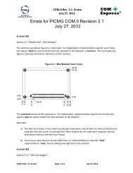
<strong>CompactPCI</strong>® <strong>PlusIO</strong> uses the user I/O pins of the system slot in order to support legacy PCI slots as<br />
well as slots based on modern serial interconnects. No bridges or switches are required for this. Ethernet<br />
can be used for multiprocessing.<br />
Figure 1. <strong>CompactPCI</strong> <strong>PlusIO</strong> System Architecture (configuration example)<br />
System Slot<br />
CPU<br />
Hub / I/O Controller<br />
PCI Express<br />
PCI Express<br />
PCI Bus<br />
SATA<br />
USB<br />
Ethernet<br />
32 bit<br />
32 bit<br />
32 bit<br />
Industrial<br />
I/O<br />
Industrial<br />
I/O<br />
Graphics<br />
Ethernet<br />
Hard<br />
Drives<br />
WiFi<br />
Ethernet<br />
Peripheral<br />
CPU<br />
Peripheral Slots<br />
2.2 <strong>CompactPCI</strong>® <strong>PlusIO</strong> Implementation Rules for Guaranteeing<br />
Interoperability<br />
<strong>CompactPCI</strong>® <strong>PlusIO</strong> – PICMG 2.30 – supports four PCI Express®, SATA and USB 2.0 interfaces as<br />
well as two Ethernet interfaces on the backplane. Not every CPU board will use all of the new interfaces<br />
– e.g. because of the costs. A typical Intel® Atom platform might perhaps only support one Ethernet<br />
and one PCIe®. It depends on the implementation whether SATA can be used. Four USB interfaces are<br />
possible if required. In order to guarantee maximum interoperability between CPU boards of different<br />
manufacturers, the PICMG 2.30 standard clearly defines the sequence in which the interfaces have to be<br />
<strong>CompactPCI</strong>® <strong>PlusIO</strong> <strong>Design</strong> <strong>Guide</strong> Page 7
"filled". This makes sure, for example, that the only PCIe® interface of one manufacturer does not<br />
collide with a differing assignment of another manufacturer.<br />
The prescribed sequence for Ethernet is ascending: 1, 2, for SATA descending: 4, 3, 2, 1; for USB and<br />
PCI Express® ascending: 1, 2, 3, 4. Except for SATA the interfaces are filled incrementing – why not<br />
the SATA interfaces?<br />
A <strong>CompactPCI</strong>® system using PICMG 2.30 can be equipped with up to four of the new <strong>CompactPCI</strong>®<br />
Serial slots on the hybrid backplane. These four slots shall be usable to the maximum even if not all<br />
interfaces can be supported by a CPU board. With four slots it would be unhandy if all interfaces were<br />
led to the first slot and none to the last. PCI Express® and USB are implemented concurrently in order<br />
to enable the use of PCI Express® MiniCards, for example. One slot will often be needed for a hard<br />
disk or an SSD. As only one interface per slot is needed in this case, the interfaces are filled descending.<br />
A system based on an Intel® Atom SBC might look like this: Ethernet on the backplane for<br />
controlling an additional computer, a video input card controlled via PCI Express® is plugged into the<br />
first peripheral slot, the second slot is equipped with a USB-based RS485 extension, slot 3 supports a<br />
WiFi interface – also USB – and slot 4 accommodates a SATA hard disk.<br />
Figure 2. Implementation example for a system based on an SBC with Intel® Atom – a CPU which<br />
does not support all PICMG 2.30 interfaces<br />
1x Ethernet<br />
1x PCIE<br />
2x SATA<br />
4x USB<br />
PCIE 1<br />
USB 1 USB 2<br />
SATA 3<br />
USB 3<br />
SATA 4<br />
USB 4<br />
System slot with PICMG 2.30 – Atom-based<br />
Peripheral slot – Video input<br />
Peripheral slot – RS485<br />
Peripheral slot – WiFi<br />
User I/O User I/O User I/O<br />
Peripheral slot – HDD<br />
User I/O<br />
<strong>CompactPCI</strong>® <strong>PlusIO</strong> <strong>Design</strong> <strong>Guide</strong> Page 8
2.3 Hybrid Backplanes for <strong>CompactPCI</strong>® and <strong>CompactPCI</strong>® <strong>PlusIO</strong><br />
(PICMG 2.30)<br />
A hybrid system with a <strong>CompactPCI</strong> <strong>PlusIO</strong> board at its center can support up to 7 <strong>CompactPCI</strong> parallel<br />
peripheral slots (as previously) and up to four <strong>CompactPCI</strong> Serial peripheral slots.<br />
Figure 3. <strong>CompactPCI</strong>® / <strong>CompactPCI</strong>® <strong>PlusIO</strong> 8-slot hybrid backplane example<br />
PICMG<br />
2.0<br />
peripheral<br />
slot<br />
PICMG<br />
2.0<br />
peripheral<br />
slot<br />
PICMG<br />
2.0<br />
peripheral<br />
slot<br />
PICMG<br />
2.0 & 2.30<br />
system<br />
slot<br />
PICMG<br />
CPCI-S.0<br />
peripheral<br />
slot<br />
PICMG<br />
CPCI-S.0<br />
peripheral<br />
slot<br />
PICMG<br />
CPCI-S.0<br />
peripheral<br />
slot<br />
PICMG<br />
CPCI-S.0<br />
peripheral<br />
slot<br />
Ethernet (optional)<br />
Legacy <strong>CompactPCI</strong> 32 bit<br />
P2 rear I/O connector (user I/O)<br />
User I/O User I/O User I/O<br />
P2 <strong>CompactPCI</strong> pinout<br />
PICMG<br />
<strong>PlusIO</strong>2.30<br />
<strong>CompactPCI</strong> Serial area<br />
for rear I/O (optional)<br />
Legacy <strong>CompactPCI</strong> 32 <strong>CompactPCI</strong> bit P1 connector<br />
<strong>CompactPCI</strong> Serial base connector<br />
The figure above shows an example of an 8-slot hybrid backplane with the three standard <strong>CompactPCI</strong><br />
peripheral slots and the system slot for the <strong>CompactPCI</strong> <strong>PlusIO</strong> CPU board on the left and the maximum<br />
number of four <strong>CompactPCI</strong> Serial peripheral slots on the right. The peripheral slots’ small connector<br />
carries the power supply, the PCIe 1x, SATA and USB (2) signals and - where used - monitoring and<br />
control lines. The Ethernet signals are carried via a separate connector and can be left unassembled to<br />
reduce backplane costs when Ethernet signals are not needed.<br />
Figure 4. Hybrid backplane example with four <strong>CompactPCI</strong>® Serial peripheral slots<br />
<strong>CompactPCI</strong>® <strong>PlusIO</strong> <strong>Design</strong> <strong>Guide</strong> Page 9
2.3.1 Recommendations for Backplane <strong>Design</strong>s<br />
It is highly recommended to use the following wiring schema (signals in the same row are connected<br />
together):<br />
Table 4. Backplane Wiring for Four Peripheral Slots<br />
System Slot Slot 1 Slot 2 Slot 3 Slot 4<br />
1_PCIE 1_PCIE<br />
2_PCIE<br />
1_PCIE<br />
3_PCIE<br />
1_PCIE<br />
4_PCIE<br />
1_PCIE<br />
1_SATA/SAS 1_SATA/SAS<br />
2_SATA/SAS<br />
1_SATA/SAS<br />
3_SATA/SAS<br />
1_SATA/SAS<br />
4_SATA/SAS<br />
1_SATA/SAS<br />
SATA_GPIO SATA_GPIO SATA_GPIO SATA_GPIO SATA_GPIO<br />
1_USB2 1_USB2<br />
2_USB2<br />
1_USB2<br />
3_USB2<br />
1_USB2<br />
4_USB2<br />
1_USB2<br />
1_ETH 1_ETH<br />
2_ETH<br />
1_ETH<br />
2_ETH *) 2_ETH *)<br />
*) point to point connection between Slot 1 and 2<br />
Table 5. Backplane Wiring for Three Peripheral Slots<br />
System Slot Slot 1 Slot 2 Slot 3<br />
1_PCIE 1_PCIE<br />
2_PCIE<br />
1_PCIE<br />
3_PCIE<br />
1_PCIE<br />
4_PCIE<br />
1_SATA/SAS<br />
2_SATA/SAS 1_SATA/SAS<br />
3_SATA/SAS<br />
1_SATA/SAS<br />
4_SATA/SAS<br />
1_SATA/SAS<br />
SATA_GPIO SATA_GPIO SATA_GPIO SATA_GPIO<br />
1_USB2 1_USB2<br />
2_USB2<br />
1_USB2<br />
3_USB2<br />
1_USB2<br />
4_USB2<br />
1_ETH 1_ETH<br />
2_ETH<br />
1_ETH<br />
2_ETH *) 2_ETH *)<br />
*) point to point connection between Slot 1 and 2<br />
<strong>CompactPCI</strong>® <strong>PlusIO</strong> <strong>Design</strong> <strong>Guide</strong> Page 10
Table 6. Backplane Wiring for Two Peripheral Slots<br />
System Slot Slot 1 Slot 2<br />
1_PCIE 1_PCIE<br />
2_PCIE 1_PCIE<br />
3_PCIE<br />
1_PCIE<br />
4_PCIE<br />
1_PCIE<br />
1_SATA/SAS<br />
2_SATA/SAS<br />
3_SATA/SAS 1_SATA/SAS<br />
4_SATA/SAS<br />
1_SATA/SAS<br />
SATA_GPIO SATA_GPIO SATA_GPIO<br />
1_USB2 1_USB2<br />
2_USB2<br />
1_USB2<br />
3_USB2<br />
4_USB2<br />
1_ETH 1_ETH<br />
2_ETH<br />
1_ETH<br />
2_ETH *) 2_ETH *)<br />
*) point to point connection between Slot 1 and 2<br />
Table 7. Backplane Wiring for One Peripheral Slot<br />
System Slot Slot 1<br />
1_PCIE 1_PCIE<br />
2_PCIE 1_PCIE<br />
3_PCIE 1_PCIE<br />
4_PCIE 1_PCIE<br />
1_SATA/SAS<br />
2_SATA/SAS<br />
3_SATA/SAS<br />
4_SATA/SAS 1_SATA/SAS<br />
SATA_GPIO SATA_GPIO<br />
1_USB2 1_USB2<br />
2_USB2<br />
3_USB2<br />
4_USB2<br />
1_ETH 1_ETH<br />
2_ETH 2_ETH<br />
2.3.2 PCI Express® Configuration Possibilities with <strong>CompactPCI</strong>® <strong>PlusIO</strong><br />
<strong>CompactPCI</strong>® <strong>PlusIO</strong> – PICMG 2.30 – permits to lead a total of four PCI Express® interfaces to the<br />
backplane. The Ultra Hard Metric connectors on the plug-in board permit data rates of up to 5 Gb/s,<br />
traditional 2-mm connectors being usable on the backplane.<br />
These four interfaces (also called links) can be used to control four PCI Express®-based peripheral<br />
boards. Each interface is equipped with one differential receive pair and a differential transmit pair – a<br />
lane. The four PCI Express® lines can, e.g., be compatible to <strong>CompactPCI</strong>® Express or to<br />
<strong>CompactPCI</strong>® Serial.<br />
Each interface reaches data rates of 250 MB/s with PCI Express® Gen1 or 500 MB/s with PCI<br />
Express® Gen2 per direction. For some applications, however, e.g., for image processing, these data<br />
rates are still not sufficient. For this reason, the PICMG Standard 2.30 <strong>CompactPCI</strong>® <strong>PlusIO</strong> allows to<br />
<strong>CompactPCI</strong>® <strong>PlusIO</strong> <strong>Design</strong> <strong>Guide</strong> Page 11
"cluster" the four PCI Express® interfaces. This way, the four links with one lane each defined for<br />
PICMG 2.30 can also be configured as two links with two lanes each or even as one link with four<br />
lanes. In the last case, theoretical data rates of 1,000 MB/s with PCI Express® Gen1 or 2,000 MB/s for<br />
Gen2 can be reached, but only with a connected device. Note that clustering is not possible with a<br />
standard backplane as shown in Figure 4 and with standard <strong>CompactPCI</strong> Serial peripheral boards as<br />
described in Chapter 1.2.1.<br />
The PICMG 2.30 CPU board imports the configuration via four control lines which are also used to<br />
activate the respective 100 MHz clock which is allocated to a PCI Express® interface. No additional<br />
lines are necessary. This way, <strong>CompactPCI</strong>® <strong>PlusIO</strong> PICMG 2.30 guarantees high flexibility for the<br />
connection of high-speed peripheral components based on PCI Express® while being 100% compatible<br />
to the established <strong>CompactPCI</strong>® standard and without needing additional infrastructure like switches or<br />
bridges – a future-safe solution.<br />
Table 8. PCI Express® configuration<br />
1_PE_CLKE# 2_PE_CLKE# 3_PE_CLKE# 4_PE_CLKE# PCI Express Config.<br />
open open open open not defined<br />
GND open open open 1 link with 4 lanes<br />
open GND open open 2 links with 2 lanes<br />
GND GND open open 2 links with 2 lanes<br />
open open GND open 4 links with 1 lane<br />
GND open GND open 4 links with 1 lane<br />
open GND GND open 4 links with 1 lane<br />
GND GND GND open 4 links with 1 lane<br />
open open open GND 4 links with 1 lane<br />
GND open open GND 4 links with 1 lane<br />
open GND open GND 4 links with 1 lane<br />
GND GND open GND 4 links with 1 lane<br />
open open GND GND 4 links with 1 lane<br />
GND open GND GND 4 links with 1 lane<br />
open GND GND GND 4 links with 1 lane<br />
GND GND GND GND 4 links with 1 lane<br />
Figure 5. Four Interfaces with 1 lane each – data rate 250/500 MB/s<br />
1 lane<br />
PCI Express I/O<br />
System slot<br />
<strong>CompactPCI</strong><br />
<strong>PlusIO</strong><br />
1 lane<br />
1 lane<br />
PCI Express I/O<br />
PCI Express I/O<br />
1 lane<br />
PCI Express I/O<br />
<strong>CompactPCI</strong>® <strong>PlusIO</strong> <strong>Design</strong> <strong>Guide</strong> Page 12
Figure 6. One interface with four lanes – data rate 1000/2000 MB/s<br />
System slot<br />
<strong>CompactPCI</strong><br />
<strong>PlusIO</strong><br />
4 lanes<br />
PCI Express I/O<br />
2.3.3 Power Requirements of Hybrid Systems<br />
The power requirements for the two parts of a <strong>CompactPCI</strong> / <strong>CompactPCI</strong> Serial hybrid system are very<br />
different, so a single standard PSU may not be enough in many cases. The <strong>CompactPCI</strong> part of a hybrid<br />
system always needs +5V supply voltage. Depending on the system configuration, +3.3V, -12V and<br />
+12V lines may also be necessary. The <strong>CompactPCI</strong> Serial part relies on a single rail +12V main power<br />
supply. An additional +5V standby voltage line is optional for certain system configurations. The<br />
backplane distributes the supply voltages to the front boards.<br />
2.3.4 Geographical Addressing in Hybrid Systems<br />
Geographical addressing for the <strong>CompactPCI</strong> and <strong>CompactPCI</strong> Serial parts of a hybrid system is<br />
handled differently and independently. Consult the standard specification for the respective system for<br />
details.<br />
<strong>CompactPCI</strong>® <strong>PlusIO</strong> <strong>Design</strong> <strong>Guide</strong> Page 13
3 Appendix: Literature and Web Resources<br />
www.compactpciserial.net<br />
The Next Generation <strong>CompactPCI</strong>®: PICMG 2.30 <strong>PlusIO</strong> and PICMG CPCI-S.0 (blog)<br />
http://www.compactpci.org<br />
Official PICMG 2.30 page<br />
<strong>CompactPCI</strong>® <strong>PlusIO</strong> <strong>Design</strong> <strong>Guide</strong> Page 14