PVSR-E volume flow controller_rectangular - Pichler
PVSR-E volume flow controller_rectangular - Pichler
PVSR-E volume flow controller_rectangular - Pichler

You also want an ePaper? Increase the reach of your titles
YUMPU automatically turns print PDFs into web optimized ePapers that Google loves.
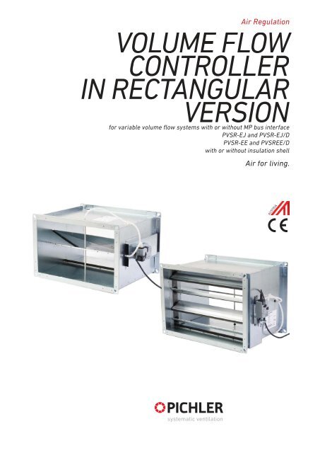
Air Regulation<br />
CONTROLLER<br />
IN RECTANGULAR<br />
VERSION<br />
for variable <strong>volume</strong> <strong>flow</strong> systems with or without MP bus interface<br />
<strong>PVSR</strong>-EJ and <strong>PVSR</strong>-EJ/D<br />
<strong>PVSR</strong>-EE and <strong>PVSR</strong>EE/D<br />
with or without insulation shell<br />
Air for living.
VOLUME FLOW CONTROLLER IN RECTANGULAR VERSION <strong>PVSR</strong>-E PAGE 2
VOLUME FLOW CONTROLLER IN RECTANGULAR VERSION <strong>PVSR</strong>-E PAGE 3<br />
Inhalt<br />
1 General Page 4<br />
1.1 FUNCTIONAL PRINCIPLE PAGE 4<br />
1.2 BENEFITS AND USES OF VAV SYSTEMS PAGE 4<br />
1.4 VOLUME FLOW MEASUREMENT PAGE 5<br />
1.3 FUNCTIONING OF VAV COMPACT DRIVES PAGE 5<br />
2 Product description Page 6<br />
3 Version Page 6<br />
3.1 <strong>PVSR</strong>-E VERSION PAGE 6<br />
3.2 DIFFERENTIAL PRESSURE MEASUREMENT PAGE 8<br />
3.3 SETTING PAGE 8<br />
3.4 INSTALLATION PAGE 8<br />
4. Layout sketch/Technical specifications Page 9<br />
4.1. DIMENSIONS PAGE 9<br />
4.2 VOLUME FLOW RANGES PAGE 11<br />
4.3 QUICK SELECTION PAGE 15<br />
4.4 ACOUSTIC DATA PAGE 16<br />
5 Installation Page 19<br />
5.1 MINIMUM FLOW PATH PAGE 19<br />
6 Technical data on VAV compact regulators Page 21<br />
6.1 ELECTRICAL DATA ON L/NMV-D3-MP WITH MP BUS ACTUATION PAGE 21<br />
6.2 ELECTRICAL DATA ON L/NMV-D3-MF WITHOUT MP BUS ACTUATION PAGE 22<br />
6.3 ELECTRICAL CONNECTION PAGE 22<br />
6.4 CONNECTION PLANS - CIRCUIT DIAGRAMS PAGE 23<br />
7 Specifications Page 26<br />
7.1 SPECIFICATIONS FOR <strong>PVSR</strong>-EJ / MP BUS / SHUTTER VALVE VERSION PAGE 26<br />
7.2 SPECIFICATIONS FOR <strong>PVSR</strong>-EJ/D / MP BUS / VERSION AS SHUTTER VALVE PAGE 27<br />
7.3 SPECIFICATIONS FOR <strong>PVSR</strong>-EJ / MF / SHUTTER VALVE VERSION PAGE 28<br />
7.4 SPECIFICATIONS FOR <strong>PVSR</strong>-EJ/D / MF / SHUTTER VALVE VERSION PAGE 29<br />
Volume <strong>flow</strong> <strong>controller</strong> also in round version, for VAV systems,<br />
available with or without MP bus interface! Page 30<br />
Note Page 31
VOLUME FLOW CONTROLLER IN RECTANGULAR VERSION <strong>PVSR</strong>-E PAGE 4<br />
1 General<br />
requirements relating to cost-effective<br />
and energy-efficient operation can be<br />
met, in particular thanks to the new type<br />
of needs-based fan regulation via the<br />
VAV valve position in combination with<br />
MP bus system generation drives. Each<br />
zone, each area in a building receive<br />
precisely the air <strong>volume</strong> <strong>flow</strong> required to<br />
maintain the criteria currently required<br />
to supply the exterior air and discharge<br />
the waste substances. The room temperature,<br />
the air quality or a combination<br />
of the two determine the required air<br />
<strong>volume</strong> <strong>flow</strong>.<br />
1 Volume <strong>flow</strong> <strong>controller</strong><br />
(differential pressure sensor, regulator with<br />
drive as VAV compact unit)<br />
2 Room temperature regulator<br />
1 Pressure sensor - orifice<br />
2 Differential pressure sensor<br />
3 Volume <strong>flow</strong> (VAV) regulator<br />
4 Reference signal 0.. 10 V<br />
5 Actuator<br />
6 Butterfly control valve<br />
1.1 FUNCTIONAL PRINCIPLE<br />
The VAV control functions as a closed<br />
control circuit: measure – compare –<br />
track. The <strong>controller</strong> receives the <strong>volume</strong><br />
<strong>flow</strong> dependent pressure signal via the<br />
differential pressure sensor integrated<br />
into the <strong>volume</strong> <strong>flow</strong> <strong>controller</strong>.<br />
The system functions dependent on system<br />
pressure, i.e. pressure fluctuations<br />
in the air lines, caused by filters or other<br />
zones, are detected and compensated<br />
for automatically.<br />
The <strong>volume</strong> <strong>flow</strong> <strong>controller</strong> is modified<br />
for the project-specific requirements<br />
on the test section. The nominal <strong>volume</strong><br />
<strong>flow</strong> Vnom as well as the operating <strong>volume</strong><br />
<strong>flow</strong> settings Vmin, Vmax are written<br />
to the regulator memory. When commissioning<br />
the system, this guarantees<br />
perfect functioning with minimum effort.<br />
1.2 BENEFITS AND USES OF VAV<br />
SYSTEMS<br />
• Demand-regulated air <strong>volume</strong> <strong>flow</strong><br />
• Pre-pressure independent system,<br />
simple system integration<br />
• Combination with other components<br />
and systems such as cooling ceilings<br />
• Compatible with energy recovery<br />
systems<br />
• Low energy consumption, shortens<br />
amortisation time<br />
• Simple actuation using 0 - 10 V signal<br />
or via bus system (MP bus, LonWorks,<br />
etc.)<br />
• Valve position is used for the energyefficient<br />
regulation of the fans<br />
• Permits a saving of up to 50 % of the<br />
energy for the fans via the Fan<br />
Optimiser
VOLUME FLOW CONTROLLER IN RECTANGULAR VERSION <strong>PVSR</strong>-E PAGE 5<br />
Supply<br />
Control variable w<br />
Sensor-<br />
Electronics<br />
A<br />
Q .<br />
Δp Sensor<br />
D<br />
M̂<br />
Δp Microprocessor<br />
z<br />
w<br />
M̂mi<br />
n<br />
M̂ma<br />
x<br />
cw ... ccw<br />
…<br />
Memory<br />
Δp @<br />
M̂ nom<br />
+<br />
–<br />
D<br />
A<br />
Communication<br />
ASIC-<br />
Controller<br />
Halomo<br />
M<br />
U 5<br />
Actual value signal<br />
10<br />
2<br />
0<br />
M̂<br />
PP/MP<br />
DRIVES<br />
In the measurement unit (sensor<br />
electronics), the differential pressure<br />
signal is converted by the sensor to a<br />
signal proportional to the <strong>volume</strong> <strong>flow</strong>.<br />
Control signal w is conditioned in line with<br />
the operational <strong>volume</strong>tric <strong>flow</strong> setting<br />
V min<br />
/ V max<br />
as a target value signal.<br />
The instantaneous offset forms the<br />
control signal for the drive integrated. The<br />
current <strong>volume</strong>tric <strong>flow</strong> is available as<br />
an actual value signal for the display and<br />
control of slave VAV regulators.<br />
+ –<br />
The specially designed runtime logic of<br />
the VAV compact, in conjunction with an<br />
accurate differential pressure recorder,<br />
guarantees high control quality of the VAV<br />
box equipped with it.<br />
A choice between traditional control signal<br />
and MP bus can be made depending on<br />
application.<br />
Δ p<br />
M̂<br />
c<br />
Legend:<br />
V = Volumetric <strong>flow</strong><br />
c = Geometry-dependent constant of the<br />
bluff body<br />
Δp = Differential pressure<br />
= Density of the medium<br />
1.4 VOLUME FLOW MEASUREMENT<br />
The basis for <strong>volume</strong>tric <strong>flow</strong><br />
measurement is a differential pressure<br />
pickup, usually fitted into the air duct in<br />
the form of an orifice gauge, a venturi<br />
nozzle or a differential pressure sensor.<br />
Several measurement methods have<br />
established themselves on the market for<br />
recording <strong>volume</strong>tric <strong>flow</strong>.<br />
Reliable and precise differential pressure<br />
measurement is the key to accurate<br />
<strong>volume</strong>tric <strong>flow</strong> regulation<br />
The measurement used by Belimo<br />
permits reliable mean value calculation<br />
even in unfavourable <strong>flow</strong> conditions.<br />
Every measurement sensor used for<br />
differential pressure recording has its<br />
own dynamic behaviour. The effect of this<br />
measurement body on the <strong>volume</strong>tric<br />
<strong>flow</strong> calculation is referred to as device<br />
constant “c”.<br />
The sensor element comprises a centrally<br />
located heating element with two<br />
temperature sensors positioned in the<br />
<strong>flow</strong> direction. Formed above the heating<br />
element is a temperature bell that is<br />
deformed by the air <strong>flow</strong> in the direction<br />
of <strong>flow</strong>. The resulting temperature<br />
difference between the two temperature<br />
sensors is a measure of the differential<br />
pressure at the sensor.
VOLUME FLOW CONTROLLER IN RECTANGULAR VERSION <strong>PVSR</strong>-E PAGE 6<br />
Features of the Belimo D3 differential<br />
pressure sensor:<br />
• Precise, proven heat transport<br />
measurement principle<br />
• Lowest <strong>flow</strong> through the sensor, hence<br />
insensitive to dirt<br />
• Zero balance not required for start-up or<br />
during operation<br />
• Suitable for any installation position<br />
• Maintenance-free and with long-term<br />
stability for a diverse range of<br />
applications<br />
• Parallel measurements possible thanks<br />
to very low air <strong>flow</strong> rate<br />
• Display of the current differential<br />
pressure, from –600 … 600 Pa<br />
• The <strong>flow</strong>-through direction is detected<br />
Calibration data<br />
Temperature-<br />
Compensation<br />
Linearisation<br />
PC-Interface<br />
A<br />
D<br />
A<br />
D<br />
Sensor<br />
Chip<br />
2 Product description<br />
Rectangular <strong>volume</strong> <strong>flow</strong> <strong>controller</strong> of<br />
types <strong>PVSR</strong>-EE and <strong>PVSR</strong>-EJ are used<br />
for variable or constant regulation of the<br />
air <strong>volume</strong> <strong>flow</strong>s in ventilation and air<br />
conditioning systems. The application<br />
for these components are restricted in<br />
usage to air conditioning systems at<br />
temperatures between + 0 °C and + 50<br />
°C, where the air is free from caustic<br />
vapours and wear-inducing substances.<br />
The <strong>volume</strong> <strong>flow</strong> <strong>controller</strong> is not<br />
suitable for open air installation.<br />
3 Version<br />
3.1 <strong>PVSR</strong>-E VERSION<br />
The <strong>rectangular</strong> <strong>volume</strong> <strong>flow</strong> <strong>controller</strong><br />
is available in two different versions, as<br />
airtight shutter valve (EJ) or as single<br />
valve (EE) and each version is available<br />
with or without insulating shell.<br />
The connecting stubs are fitted with<br />
universal connection flanges on both<br />
sides, to fit flange connections P20 and<br />
P30. In the version with insulating shell,<br />
the <strong>volume</strong> <strong>flow</strong> <strong>controller</strong> is surrounded<br />
with mineral wool and an external<br />
sheath made from zinc-plated steel<br />
plate to reduce cabinet radiation.<br />
To maintain the permissible sound<br />
pressure level in the room, it can also<br />
be necessary to install a sound absorber<br />
between the <strong>volume</strong> <strong>flow</strong> <strong>controller</strong> and<br />
the room and to insulate the air line.<br />
The insulating shell cannot be<br />
retrofitted.<br />
2.1.1 Airtight shutter valve EJ version<br />
The <strong>volume</strong> <strong>flow</strong> <strong>controller</strong> comprises a<br />
cabinet made from zinc-plated steel plate<br />
with integrated control and airtight shutoff<br />
valve. The control and shut-off valve<br />
is designed as an airtight shutter valve<br />
with sealing lips on the blades.<br />
The sealing on the side of the blades to<br />
the cabinet is implemented using an allround,<br />
permanently elastic sealing strip.<br />
The blades are driven using anti-static<br />
plastic toothed wheels fitted on the<br />
outside. The current position of the<br />
control and shut-off valve can be seen<br />
from outside on the axis via a marker.<br />
The valve in shut-off position is airtight<br />
according to class 4 conforming to<br />
ÖNORM EN 1751 For the leaked air<br />
<strong>volume</strong> <strong>flow</strong> of the cabinet, class C is<br />
achieved conforming to ÖNORM EN 1751.<br />
2.1.2 Single valve EE version<br />
The <strong>volume</strong> <strong>flow</strong> <strong>controller</strong> comprises<br />
a cabinet made from zinc-plated steel<br />
plate with integrated control and shutoff<br />
valve. The valve blade is a single<br />
rotary valve with an all-round ageingresistant<br />
and permanently elastic seal.<br />
The current position of the control and<br />
shut-off valve can be seen from outside<br />
on the axis via a marker.<br />
The valve in shut-off position is airtight<br />
according to class 2 conforming to<br />
ÖNORM EN 1751 For the leaked air<br />
<strong>volume</strong> <strong>flow</strong> of the cabinet, class C is<br />
achieved conforming to ÖNORM EN 1751.
VOLUME FLOW CONTROLLER IN RECTANGULAR VERSION <strong>PVSR</strong>-E PAGE 7<br />
Airtight shutter valve EJ version<br />
Control and shut-off valve with permanently<br />
elastic seal as airtight shutter valve<br />
Type MF actuator or<br />
MP with control components<br />
<strong>PVSR</strong>-EJ - without insulating shell<br />
Measurement sensor<br />
for the differential pressure<br />
Universal connection flange for<br />
P20/P30 air line connection<br />
Single valve EE version<br />
Control and shut-off valve with permanently<br />
ela<br />
stic seal as airtight shutter valve<br />
Type MF actuator or<br />
MP with control components<br />
Measurement sensor<br />
for the differential pressure<br />
Universal connection flange for<br />
P20/P30 air line connection
VOLUME FLOW CONTROLLER IN RECTANGULAR VERSION <strong>PVSR</strong>-E PAGE 8<br />
1 Pressure sensor - orifice<br />
2 Differential pressure sensor<br />
3 Volume <strong>flow</strong> (VAV) regulator<br />
4 Reference signal 0.. 10 V or 2.. 10 V<br />
5 Actuator<br />
6 Butterfly control valve<br />
REMENT<br />
The differential pressure measurement<br />
is carried out using a differential pressure<br />
sensor made from hollow round<br />
pipe profiles on which for mean value<br />
calculation measurement holes are<br />
given on the low pressure and overpressure<br />
sides in accordance with the<br />
median procedure conforming to ÖNORM<br />
EN 12599.<br />
This achieves a higher level of accuracy<br />
in comparison to standard measurement<br />
devices with fewer measurement<br />
holes or other measuring orifices. This<br />
means that on installation the necessary<br />
<strong>flow</strong> path in front of the <strong>volume</strong> <strong>flow</strong><br />
<strong>controller</strong> is kept short (see Installation<br />
chapter).<br />
For the proper functioning of the <strong>volume</strong><br />
<strong>flow</strong> control unit, measures should be<br />
taken to exclude the risk of contamination<br />
(e.g. dust ingression) of the control<br />
components. This can be achieved by<br />
installing a suitable air filter in the air<br />
line system.<br />
For applications with air containing<br />
grease (e.g. waste kitchen air), air with<br />
sticky components or for heavily contaminated<br />
air, or air containing flyings or<br />
corrosive air, the <strong>volume</strong> <strong>flow</strong> <strong>controller</strong><br />
is not suitable.<br />
3.3 SETTING<br />
The <strong>volume</strong> <strong>flow</strong> <strong>controller</strong> is pre-assembled<br />
in the factory using the control<br />
component as a finished unit. The pressure<br />
sensor is connected via pipe to the<br />
regulator and set to the air <strong>volume</strong> <strong>flow</strong>s<br />
according to customer requirements in<br />
line with the settings. The set operating<br />
air <strong>volume</strong> <strong>flow</strong>s Vmin and Vmax can<br />
also be easily modified on site at any<br />
time using a manual adjusting device<br />
or software (PC tool), in fully assembled<br />
status.<br />
Before delivery, each unit is subjected to<br />
a technical functional test on a specially<br />
prepared test rig. The factory settings<br />
are documented on the nameplate.<br />
3.4 INSTALLATION<br />
Following the installation instructions<br />
and a technical layout conforming to to<br />
the relevant <strong>flow</strong> guidelines, the <strong>volume</strong><br />
<strong>flow</strong> <strong>controller</strong> can be installed in the<br />
control system regardless of position.<br />
On installation, the installation directions<br />
given on the nameplate must be<br />
observed. The installation instructions<br />
provided by the manufacturer must also<br />
be observed.
VOLUME FLOW CONTROLLER IN RECTANGULAR VERSION <strong>PVSR</strong>-E PAGE 9<br />
4. Layout sketch/Technical specifications<br />
4.1.1 Airtight shutter valves <strong>PVSR</strong>-EJ and<br />
<strong>PVSR</strong>-EJ/D<br />
<strong>PVSR</strong>-EJ - without insulating shell<br />
<strong>PVSR</strong>-EJ/D - with insulating shell<br />
Dimensions<br />
Weight [kg]<br />
Clear height<br />
H<br />
Clear width<br />
W<br />
Length L<br />
Distance A<br />
Insulation<br />
thickness D<br />
Height H1<br />
Width W1<br />
Flange<br />
<strong>PVSR</strong><br />
EJ<br />
<strong>PVSR</strong><br />
EJ/D<br />
mm mm mm mm mm mm mm approx. kg approx. kg<br />
200<br />
300<br />
5.8 12<br />
300 400 7.2 15<br />
200<br />
400 300 500 8.6 18<br />
500 600 10.1 21<br />
600 700 11.5 24<br />
300<br />
400 8.6 18<br />
400 500 10.1 21<br />
300<br />
400<br />
500<br />
500 600 11.5 24<br />
400<br />
600 700 13.5 27<br />
700 800 14.4 30<br />
800 900 15.8 33<br />
400<br />
700 500 800 15.8 33<br />
400 85 50<br />
800 900 17.3 36<br />
Universal flange to fit P30 / P20 air line connection<br />
500 11.5 24<br />
500 600 13.0 27<br />
600 700 14.4 30<br />
900 1000 18.7 39<br />
1000 1100 20.2 42<br />
500<br />
600 14.4 30<br />
600 700 15.8 33<br />
700 800 17.3 36<br />
600<br />
800 900 18.7 39<br />
900 1000 20.2 42<br />
1000 1100 21.6 45<br />
600<br />
700 17.3 36<br />
600<br />
800 700 900 20.2 42<br />
1000 1100 23 48<br />
800<br />
800<br />
900 23 48<br />
900<br />
1000 1100 26 54<br />
1000 1000 1100 1100 29 60
VOLUME FLOW CONTROLLER IN RECTANGULAR VERSION <strong>PVSR</strong>-E PAGE 10<br />
<strong>PVSR</strong>-EE/D<br />
<strong>PVSR</strong>-EE - without insulating shell<br />
<strong>PVSR</strong>-EE/D - with insulating shell<br />
Dimensions<br />
Weight [kg]<br />
Clear height<br />
H<br />
Clear width<br />
W<br />
Length L<br />
Distance A<br />
Insulating<br />
thickness D<br />
Height H1<br />
Width W1<br />
Flange<br />
<strong>PVSR</strong><br />
EJ<br />
<strong>PVSR</strong><br />
EJ/D<br />
mm mm mm mm mm mm mm approx. kg approx. kg<br />
200<br />
300<br />
200<br />
300<br />
400 400<br />
300 500 8.6 18<br />
300<br />
85 50<br />
Universal flange to fit P30 / P20 air line connection<br />
5.8 12<br />
300 400 7.2 15<br />
500 600 10.1 21<br />
600 700 11.5 24<br />
400 8.6 18<br />
400 500 10.1 21<br />
500 600 11.5 24<br />
450 400<br />
600 700 13.0 27<br />
700 800 14.4 30<br />
800 900 15.8 33
VOLUME FLOW CONTROLLER IN RECTANGULAR VERSION <strong>PVSR</strong>-E PAGE 11<br />
4.2.1 Airtight shutter valves <strong>PVSR</strong>-EJ and<br />
<strong>PVSR</strong>-EJ/D<br />
Installation height 200 and 300 mm<br />
<strong>PVSR</strong>-EJ - without insulating shell<br />
<strong>PVSR</strong>-EJ/D - with insulating shell<br />
Size<br />
A<br />
V<br />
W/H min<br />
V max<br />
vK<br />
Volume <strong>flow</strong><br />
H W<br />
m²<br />
m³/h m³/h m/s<br />
m³/h l/s<br />
2 288 80<br />
Size<br />
A<br />
V<br />
W/H min<br />
V max<br />
vK<br />
Volume <strong>flow</strong><br />
H W<br />
m²<br />
m³/h m³/h m/s<br />
m³/h l/s<br />
2 648 180<br />
200 0.04 1.00 288<br />
449<br />
to<br />
1498<br />
3 432 120<br />
5 720 200<br />
7 1008 280<br />
300 0.09 1.00 648<br />
1001<br />
to<br />
3337<br />
3 972 270<br />
5 1620 450<br />
7 2268 630<br />
10 1498 416<br />
10 3337 927<br />
2 432 120<br />
2 864 240<br />
300 0.06 0.67 432<br />
667<br />
to<br />
2225<br />
3 648 180<br />
5 1080 300<br />
7 1512 420<br />
400 0.12 0.75 864<br />
1335<br />
to<br />
4450<br />
3 1296 360<br />
5 2160 600<br />
7 3024 840<br />
10 2225 618<br />
10 4450 1236<br />
2 576 160<br />
2 1080 300<br />
200<br />
400 0.08 0.50 576<br />
890<br />
to<br />
2966<br />
3 864 240<br />
5 1440 400<br />
7 2016 560<br />
500 0.15 0.60 1080<br />
1669<br />
to<br />
5562<br />
3 1620 450<br />
5 2700 750<br />
7 3780 1050<br />
10 2966 824<br />
2 720 200<br />
300<br />
10 5562 1545<br />
2 1296 360<br />
500 0.10 0.40 720<br />
1123<br />
to<br />
3744<br />
3 1080 300<br />
5 1800 500<br />
7 2520 700<br />
600 0.18 0.50 1296<br />
2002<br />
to<br />
6674<br />
3 1944 540<br />
5 3240 900<br />
7 4536 1260<br />
10 3744 1040<br />
10 6674 1854<br />
2 864 240<br />
2 1512 420<br />
600 0.12 0.33 864<br />
1348<br />
to<br />
4493<br />
3 1296 360<br />
5 2160 600<br />
7 3024 840<br />
700 0.21 0.43 1512<br />
2347<br />
to<br />
7825<br />
3 2268 630<br />
5 3780 1050<br />
7 5292 1470<br />
10 4493 1248<br />
10 7825 2174<br />
2 1728 480<br />
800 0.24 0.38 1728<br />
2644<br />
to<br />
8813<br />
3 2592 720<br />
5 4320 1200<br />
7 6048 1680<br />
10 8813 2448
VOLUME FLOW CONTROLLER IN RECTANGULAR VERSION <strong>PVSR</strong>-E PAGE 12<br />
<strong>PVSR</strong>-EJ - without insulating shell<br />
<strong>PVSR</strong>-EJ/D - with insulating shell<br />
Size<br />
A<br />
V<br />
W/H min<br />
V max<br />
vK<br />
Volume <strong>flow</strong><br />
H W<br />
m²<br />
m³/h m³/h m/s<br />
m³/h l/s<br />
2 1152 320<br />
Size<br />
Volume <strong>flow</strong><br />
A<br />
V<br />
W/H min<br />
V max<br />
vK<br />
m²<br />
m³/h m³/h m/s<br />
H W m³/h l/s<br />
400<br />
400 0.16 1.00 1152<br />
500 0.20 0.80 1440<br />
600 0.24 0.67 1728<br />
700 0.28 0.57 2016<br />
800 0.32 0.50 2304<br />
900 0.36 0.44 2592<br />
1000 0.40 0.40 2880<br />
1763<br />
to<br />
5875<br />
2203<br />
to<br />
7344<br />
2644<br />
to<br />
8813<br />
3084<br />
to<br />
10282<br />
3525<br />
to<br />
11750<br />
3966<br />
to<br />
13219<br />
4428<br />
to<br />
14760<br />
3 1728 480<br />
5 2880 800<br />
7 4032 1120<br />
10 5875 1632<br />
2 1440 400<br />
3 2160 600<br />
5 3600 1000<br />
7 5040 1400<br />
10 7344 2040<br />
2 1728 480<br />
3 2592 720<br />
5 4320 1200<br />
7 6048 1680<br />
10 8813 2448<br />
2 2016 560<br />
3 3024 840<br />
5 5040 1400<br />
7 7056 1960<br />
10 10282 2856<br />
2 2304 640<br />
3 3456 960<br />
5 5760 1600<br />
7 8064 2240<br />
10 11750 3264<br />
2 2592 720<br />
3 3888 1080<br />
5 6480 1800<br />
7 9072 2520<br />
10 13219 3672<br />
2 2880 800<br />
3 4320 1200<br />
5 7200 2000<br />
7 10080 2800<br />
500<br />
500 0.25 1.00 1800<br />
600 0.30 0.83 2160<br />
700 0.35 0.71 2520<br />
800 0.40 0.63 2880<br />
900 0.45 0.56 3240<br />
1000 0.50 0.50 3600<br />
2754<br />
to<br />
9180<br />
3305<br />
to<br />
11016<br />
3837<br />
to<br />
12789<br />
4385<br />
to<br />
14616<br />
4957<br />
to<br />
16524<br />
5508<br />
to<br />
18360<br />
2 1800 500<br />
3 2700 750<br />
5 4500 1250<br />
7 6300 1750<br />
10 9180 2550<br />
2 2160 600<br />
3 3240 900<br />
5 5400 1500<br />
7 7560 2100<br />
10 11016 3060<br />
2 2520 700<br />
3 3780 1050<br />
5 6300 1750<br />
7 8820 2450<br />
10 12789 3553<br />
2 2880 800<br />
3 4320 1200<br />
5 7200 2000<br />
7 10080 2800<br />
10 14616 4060<br />
2 3240 900<br />
3 4860 1350<br />
5 8100 2250<br />
7 11340 3150<br />
10 16524 4590<br />
2 3600 1000<br />
3 5400 1500<br />
5 9000 2500<br />
7 12600 3500<br />
10 18360 5100<br />
10 14760 4100
VOLUME FLOW CONTROLLER IN RECTANGULAR VERSION <strong>PVSR</strong>-E PAGE 13<br />
1000 mm<br />
<strong>PVSR</strong>-EJ - without insulating shell<br />
<strong>PVSR</strong>-EJ/D - with insulating shell<br />
Size<br />
A<br />
V<br />
W/H min<br />
V max<br />
vK<br />
Volume <strong>flow</strong><br />
H W<br />
m²<br />
m³/h m³/h m/s<br />
m³/h l/s<br />
2 2592 720<br />
Size<br />
A<br />
V<br />
W/H min<br />
V max<br />
vK<br />
Volume <strong>flow</strong><br />
H W<br />
m²<br />
m³/h m³/h m/s<br />
m³/h l/s<br />
2 4608 1280<br />
600 0.36 1.00 2592<br />
3946<br />
to<br />
13154<br />
3 3888 1080<br />
5 6480 1800<br />
7 9072 2520<br />
800 0.64 1.00 4608<br />
7050<br />
to<br />
23501<br />
3 6912 1920<br />
5 11520 3200<br />
7 16128 4480<br />
10 13154 3654<br />
2 3456 960<br />
800<br />
10 23501 6528<br />
2 5760 1600<br />
600<br />
800 0.48 0.75 3456<br />
5236<br />
to<br />
17453<br />
3 5184 1440<br />
5 8640 2400<br />
7 12096 3360<br />
1000 0.80 0.80 5760<br />
8770<br />
to<br />
29232<br />
3 8640 2400<br />
5 14400 4000<br />
7 20160 5600<br />
10 17453 4848<br />
10 29232 8120<br />
2 4320 1200<br />
1000 0.60 0.60 4320<br />
6610<br />
to<br />
22032<br />
3 6480 1800<br />
5 10800 3000<br />
7 15120 4200<br />
Size<br />
A<br />
Vmin Vmax vK<br />
Volume <strong>flow</strong><br />
W/H<br />
H W<br />
m²<br />
m³/h m³/h m/s<br />
m³/h l/s<br />
2 7200 2000<br />
10 22032 6120<br />
1000<br />
1000 1.00 1.00 7200<br />
10908<br />
to<br />
36360<br />
3 10800 3000<br />
5 18000 5000<br />
7 25200 7000<br />
10 36360 10100
VOLUME FLOW CONTROLLER IN RECTANGULAR VERSION <strong>PVSR</strong>-E PAGE 14<br />
<strong>PVSR</strong>-EE/D<br />
Installation heights 200 and 300 mm<br />
<strong>PVSR</strong>-EE - without insulating shell<br />
<strong>PVSR</strong>-EE/D - with insulating shell<br />
Size<br />
A<br />
V<br />
W/H min<br />
V max<br />
vK<br />
Volume <strong>flow</strong><br />
H W<br />
m²<br />
m³/h m³/h m/s<br />
m³/h l/s<br />
2 288 80<br />
Size<br />
A<br />
V<br />
W/H min<br />
V max<br />
vK<br />
Volume <strong>flow</strong><br />
H W<br />
m²<br />
m³/h m³/h m/s<br />
m³/h l/s<br />
2 648 180<br />
200 0.04 1.00 288<br />
449<br />
to<br />
1498<br />
3 432 120<br />
5 720 200<br />
7 1008 280<br />
300 0.09 1.00 648<br />
1001<br />
to<br />
3337<br />
3 972 270<br />
5 1620 450<br />
7 2268 630<br />
10 1498 416<br />
10 3337 927<br />
2 432 120<br />
2 864 240<br />
300 0.06 0.67 432<br />
667<br />
to<br />
2225<br />
3 648 180<br />
5 1080 300<br />
7 1512 420<br />
400 0.12 0.75 864<br />
1335<br />
to<br />
4450<br />
3 1296 360<br />
5 2160 600<br />
7 3024 840<br />
10 2225 618<br />
10 4450 1236<br />
2 576 160<br />
2 1080 300<br />
200<br />
400 0.08 0.50 576<br />
890<br />
to<br />
2966<br />
3 864 240<br />
5 1440 400<br />
7 2016 560<br />
500 0.15 0.60 1080<br />
1669<br />
to<br />
5562<br />
3 1620 450<br />
5 2700 750<br />
7 3780 1050<br />
10 2966 824<br />
2 720 200<br />
300<br />
10 5562 1545<br />
2 1296 360<br />
500 0.10 0.40 720<br />
1123<br />
to<br />
3744<br />
3 1080 300<br />
5 1800 500<br />
7 2520 700<br />
600 0.18 0.50 1296<br />
2002<br />
to<br />
6674<br />
3 1944 540<br />
5 3240 900<br />
7 4536 1260<br />
10 3744 1040<br />
10 6674 1854<br />
2 864 240<br />
2 1512 420<br />
600 0.12 0.33 864<br />
1348<br />
to<br />
4493<br />
3 1296 360<br />
5 2160 600<br />
7 3024 840<br />
700 0.21 0.43 1512<br />
2347<br />
to<br />
7825<br />
3 2268 630<br />
5 3780 1050<br />
7 5292 1470<br />
10 4493 1248<br />
10 7825 2174<br />
2 1728 480<br />
800 0.24 0.38 1728<br />
2644<br />
to<br />
8813<br />
3 2592 720<br />
5 4320 1200<br />
7 6048 1680<br />
10 8813 2448
VOLUME FLOW CONTROLLER IN RECTANGULAR VERSION <strong>PVSR</strong>-E PAGE 15<br />
4.3 QUICK SELECTION<br />
The <strong>volume</strong> <strong>flow</strong> <strong>controller</strong> is designed<br />
for the optimum application depending<br />
on the air <strong>volume</strong> <strong>flow</strong>. Air speeds<br />
below 2 m/s and over 10 m/s should be<br />
avoided due to the response characteristics<br />
of the regulator and the acoustics.<br />
4.3.1 Airtight shutter valve <strong>PVSR</strong>-EJ<br />
The acoustic conditions and specifications<br />
must always be observed during<br />
the planning work. To maintain the<br />
permissible sound pressure level in<br />
the room, it can be necessary to install<br />
a sound absorber in the room and to<br />
insulate the air line.<br />
Sizes 200 x 200 mm to 400 x 1000 mm<br />
Overall height<br />
Air <strong>volume</strong> <strong>flow</strong> [m 3 /h]<br />
Sizes 500 x 500 mm to 1000 x 1000 mm<br />
Overall height<br />
Air <strong>volume</strong> <strong>flow</strong> [m 3 /h] x 1000
VOLUME FLOW CONTROLLER IN RECTANGULAR VERSION <strong>PVSR</strong>-E PAGE 16<br />
The acoustic conditions and specifications<br />
must always be observed during<br />
the planning work. To maintain the<br />
permissible sound pressure level in the<br />
room, it can be necessary to install a<br />
sound absorber between the <strong>volume</strong><br />
<strong>flow</strong> <strong>controller</strong> and the room and to<br />
insulate the air line.<br />
Sizes 200 x 200 mm to 300 x 800 mm<br />
Overall height<br />
Air <strong>volume</strong> <strong>flow</strong> [m 3 /h]<br />
4.4 ACOUSTIC DATA<br />
Height<br />
[mm]<br />
Width [mm]<br />
200 300 400 500 600 700 800 900 1000<br />
200 0.04 0.06 0.08 0.10 0.12 0.14 0.16 0.18 0.20<br />
300 0.06 0.09 0.12 0.15 0.18 0.21 0.24 0.27 0.30<br />
400 0.08 0.12 0.16 0.20 0.24 0.28 0.32 0.36 0.40<br />
500 0.10 0.15 0.20 0.25 0.30 0.35 0.40 0.45 0.50<br />
600 0.12 0.18 0.24 0.30 0.36 0.42 0.48 0.54 0.60<br />
800 0.16 0.24 0.32 0.40 0.48 0.56 0.64 0.72 0.80<br />
1000 0.20 0.30 0.40 0.50 0.60 0.70 0.80 0.90 1.00<br />
Table 1 - Free <strong>flow</strong> surfaces A in m² depending on the dimensions W x H
VOLUME FLOW CONTROLLER IN RECTANGULAR VERSION <strong>PVSR</strong>-E PAGE 17<br />
Dpt = 125 Pa Dpt = 250 Pa Dpt = 500 Pa<br />
free<br />
surface A<br />
m²<br />
vL<br />
m/s<br />
63 Hz<br />
125 Hz<br />
Lw [dB/oct]<br />
250 Hz<br />
500 Hz<br />
1000 Hz<br />
2000 Hz<br />
4000 Hz<br />
8000 Hz<br />
L WA<br />
[dB(A)]<br />
63 Hz<br />
125 Hz<br />
Lw [dB/oct]<br />
250 Hz<br />
500 Hz<br />
1000 Hz<br />
2000 Hz<br />
4000 Hz<br />
8000 Hz<br />
L WA<br />
[dB(A)]<br />
63 Hz<br />
125 Hz<br />
Lw [dB/oct]<br />
250 Hz<br />
500 Hz<br />
1000 Hz<br />
2000 Hz<br />
4000 Hz<br />
8000 Hz<br />
L WA<br />
[dB(A)]<br />
3 49 50 44 46 48 47 42 36 53 56 52 47 50 52 55 52 47 59 59 56 50 54 60 63 63 59 68<br />
Row Z1<br />
0.04<br />
Row Z2<br />
0.10<br />
Row Z3<br />
0.25<br />
Row Z4<br />
0.50<br />
Row Z5<br />
1.0<br />
5 56 57 50 48 50 50 46 39 55 62 59 53 53 55 56 54 50 62 65 64 57 58 62 63 63 61 69<br />
7 62 62 53 51 52 51 48 42 57 67 64 57 56 57 58 56 52 64 70 69 62 61 63 64 64 62 70<br />
10 66 67 56 53 54 53 50 44 60 71 68 61 58 59 59 58 54 65 74 75 66 64 64 65 65 63 72<br />
3 55 54 49 47 50 51 45 40 56 60 56 53 52 54 58 54 51 62 64 60 58 58 62 67 65 62 71<br />
5 63 61 55 50 52 53 49 44 58 67 63 58 56 57 60 57 54 65 70 68 65 62 64 67 65 64 72<br />
7 68 66 58 52 54 55 51 47 60 72 68 63 58 59 61 59 56 67 75 73 70 65 65 68 66 65 74<br />
10 72 71 61 54 56 57 53 49 63 76 73 67 61 61 63 60 58 69 79 79 74 68 67 68 67 66 75<br />
3 62 58 54 49 52 55 48 45 59 64 61 58 55 57 61 56 54 65 69 64 66 62 65 70 68 64 74<br />
5 69 65 60 52 54 57 51 49 62 71 68 64 59 60 63 59 57 68 75 72 73 66 67 70 68 66 75<br />
7 74 70 63 54 56 59 54 51 64 76 73 68 62 62 64 61 59 70 80 77 78 69 68 71 69 67 77<br />
10 78 75 66 56 58 61 56 54 66 80 78 72 64 64 66 63 61 72 84 83 82 72 70 71 70 68 79<br />
3 66 61 58 50 53 58 51 49 62 68 65 62 57 58 64 59 57 68 73 67 72 65 66 73 69 67 76<br />
5 74 68 64 53 55 60 54 52 64 75 72 68 60 61 66 62 60 70 79 75 79 69 68 73 69 69 78<br />
7 79 73 67 55 57 62 57 55 67 80 77 72 63 63 67 63 62 72 84 80 84 72 69 74 70 70 80<br />
10 83 78 70 57 59 64 59 58 69 84 82 76 65 65 69 65 64 75 88 86 88 75 71 74 71 71 83<br />
3 71 64 62 52 54 61 53 52 64 72 68 67 59 60 67 61 59 70 77 70 79 68 68 75 71 69 79<br />
5 78 71 67 54 57 63 57 56 67 78 75 72 63 63 69 64 62 73 83 78 85 72 70 75 72 71 82<br />
7 83 76 70 56 58 65 60 58 70 83 81 76 65 65 70 66 64 75 88 84 90 75 71 76 73 72 84<br />
10 88 81 74 58 60 66 62 60 72 87 85 80 68 66 71 67 66 77 92 89 95 78 72 77 73 73 88<br />
Table 2 - Flow noise<br />
Definition<br />
A [m²] Free <strong>flow</strong> cross-section<br />
L w<br />
[dB(A)] Sound power level generated by <strong>flow</strong> noise<br />
v L<br />
[m/s] Flow speed in the air line<br />
Dp t<br />
[Pa] Total pressure difference<br />
Correction values for conversion to other<br />
free surfaces<br />
For free surfaces not given in the table,<br />
the A-evaluated sound power level is<br />
calculated using a correction factor.<br />
Flow surface<br />
W x H [m²]<br />
Reference to<br />
row<br />
Correction<br />
factor<br />
0.04 0.06 0.08 0.10 0.16 0.20 0.25 0.30 0.40 0.50 0.60 0.80 1.0<br />
Z1 Z2 Z3 Z4 Z5<br />
0 +1 -1 0 -2 -1 0 -2 -1 0 -3 -2 0
VOLUME FLOW CONTROLLER IN RECTANGULAR VERSION <strong>PVSR</strong>-E PAGE 18<br />
Where lines are laid through rooms, the<br />
sound radiation is carried out via the line<br />
surface, due to internal sound sources,<br />
such as fans, <strong>flow</strong> noise from installed<br />
components in the air line.<br />
The sound pressure level depends on<br />
the sound pressure level in the air line,<br />
line surface, line shape (round or <strong>rectangular</strong><br />
version), wall thickness, room<br />
insulation and distance to the air line.<br />
In the table given below, radiation noise<br />
specifications are shown relating solely<br />
to the <strong>flow</strong> noise of the <strong>volume</strong> <strong>flow</strong><br />
<strong>controller</strong>.<br />
free<br />
surface A<br />
m²<br />
vL<br />
[m/s]<br />
Total sound output level L W1<br />
in dB(A)<br />
without insulating shell, pressure difference Dp t<br />
with 50 mm insulating shell, pressure difference Dp t<br />
125 Pa 250 Pa 500 Pa 125 Pa 250 Pa 500 Pa<br />
3 32 36 42 19 22 26<br />
0.04<br />
5 37 41 46 26 28 33<br />
7 42 45 50 31 33 38<br />
10 46 49 55 36 37 44<br />
3 36 40 46 23 26 30<br />
0.10<br />
5 41 45 50 30 33 37<br />
7 46 49 55 35 37 42<br />
10 50 53 59 40 42 48<br />
3 40 44 50 27 31 35<br />
0.25<br />
5 45 49 56 34 37 42<br />
7 50 53 60 39 42 47<br />
10 54 58 65 44 47 52<br />
3 43 47 54 31 35 39<br />
0.50<br />
5 49 53 60 38 41 46<br />
7 53 57 65 43 46 51<br />
10 58 62 69 48 51 56<br />
3 53 59 68 44 49 57<br />
1.0<br />
5 58 63 73 50 54 63<br />
7 61 66 76 55 59 68<br />
10 65 70 81 59 63 73<br />
Table 3 - radiated noise - sound power level<br />
with or without insulating shell. For free surfaces<br />
between the values given, the sound<br />
power levels are calculated via interpolation.<br />
Definitions:<br />
A [m²] Free <strong>flow</strong> cross-section<br />
L w1<br />
[dB(A)] Sound power level radiation noise<br />
v L<br />
[m/s] Flow speed<br />
D pt<br />
[Pa] Total pressure difference
VOLUME FLOW CONTROLLER IN RECTANGULAR VERSION <strong>PVSR</strong>-E PAGE 19<br />
5 Installation<br />
for use as a product and must first<br />
be commissioned once it has been<br />
installed and connected in the technical<br />
ventilation system, and the electrics<br />
connected correctly and in line with the<br />
regulations. The <strong>volume</strong> <strong>flow</strong> <strong>controller</strong><br />
is not suitable for open air installation.<br />
The installation must only be carried<br />
out by trained, specialist personnel,<br />
observing both the legal and official<br />
regulations and standards. The device<br />
must not be used outside the specified<br />
area of application. Depending on the<br />
position, the <strong>volume</strong> <strong>flow</strong> <strong>controller</strong><br />
can be installed in the control system<br />
with the axes in a horizontal or vertical<br />
position. The installation must be carried<br />
out according to the <strong>flow</strong> direction given<br />
on the nameplate.<br />
Measurement pipes must not be bent!<br />
Check for correct seating during<br />
installation! The measurement sensor<br />
with the measurement lines (differential<br />
pressure sensor) must not be used on<br />
site for transport purposes.<br />
For proper functioning, measures<br />
should be taken to exclude the risk of<br />
contamination (e.g. dust ingression) of<br />
the control<br />
components. This can be carried out by<br />
installing suitable filter units in the air<br />
control system in front of the <strong>volume</strong><br />
<strong>flow</strong> <strong>controller</strong>.<br />
During installation, check for clear access<br />
for inspection and cleaning purposes. The<br />
equipment is maintenance-free in terms<br />
of its mechanical components. According<br />
to the local conditions, however, it can be<br />
necessary to fit access openings in the<br />
air lines.<br />
If larger <strong>volume</strong> <strong>flow</strong> deviations have<br />
been determined, check the measuring<br />
equipment, the connecting nipple and<br />
the connection pipes and if necessary,<br />
clean the equipment dry. When using<br />
the <strong>volume</strong> <strong>flow</strong> <strong>controller</strong>, e.g. in roof<br />
control centres, condensate can occur in<br />
the <strong>volume</strong> <strong>flow</strong> <strong>controller</strong> measurement<br />
pipes due to greater temperature<br />
differences.<br />
The condensate can impair the sensor<br />
function or damage it. Take precautions<br />
to prevent the formation of condensate<br />
using suitable measures on site, e.g. by<br />
insulating the measurement pipes.<br />
5.1 MINIMUM FLOW PATH<br />
For the correct functioning of the <strong>volume</strong><br />
<strong>flow</strong> <strong>controller</strong>, it is essential that the<br />
minimum distances to other installed<br />
components are observed during<br />
installation.<br />
A minimum <strong>flow</strong> path with the following<br />
length must be observed: L = approx. 2 x<br />
measure the diagonal measurement and<br />
implement.
VOLUME FLOW CONTROLLER IN RECTANGULAR VERSION <strong>PVSR</strong>-E PAGE 20<br />
components, such as shaped parts with<br />
or without installed components, e.g.<br />
fire dampers, sound absorbers, etc.<br />
require greater minimum <strong>flow</strong> distances.<br />
Particular care must be taken in the<br />
case of deviations to the favourable<br />
technical <strong>flow</strong> of the measurement<br />
sensor (differential pressure sensor)<br />
during installation.<br />
Minimum <strong>flow</strong> length<br />
Distance<br />
Offsets, arcs<br />
Other fittings such as diverters,<br />
T-pieces, reductions,<br />
Components such as fire<br />
dampers, sound absorbers<br />
1 x diagonal measurement<br />
2 x diagonal measurement<br />
2 x diagonal measurement<br />
D … Diagonal measurement of the <strong>volume</strong> <strong>flow</strong> <strong>controller</strong><br />
For different application situations, the<br />
minimum <strong>flow</strong> paths are given in the<br />
diagrams below.<br />
Flow path after bend<br />
Flow path after fire damper<br />
Flow path after shaped part (fork, reduction, etc. ...)<br />
Flow path after sound absorber
VOLUME FLOW CONTROLLER IN RECTANGULAR VERSION <strong>PVSR</strong>-E PAGE 21<br />
6 Technical data on VAV compact regulators<br />
Volume <strong>flow</strong> <strong>controller</strong>s <strong>PVSR</strong>–R and<br />
<strong>PVSR</strong>–RD with VAV compact regulators<br />
are all available either with or without<br />
MP bus actuation.<br />
Caution: In the version of the <strong>volume</strong> <strong>flow</strong><br />
<strong>controller</strong> with the compact regulator of<br />
type MF, it is not possible to implement a<br />
number of applications such as<br />
LONWORKS® / EIB-Konnex bus connections<br />
or Fan Optimiser.<br />
Electrical connection<br />
Nominal voltage<br />
Functional range<br />
Connection cable<br />
Protection rating<br />
24 V AC, 50 / 60 Hz<br />
24 V DC<br />
19.2 V to 28.8 V AC<br />
21.6 V bis 28.8 V DC<br />
4 x 0.75 mm²<br />
IP 54, safety class III safety extra-low voltage<br />
Operating <strong>volume</strong> <strong>flow</strong> V nom<br />
specific nominal <strong>volume</strong> <strong>flow</strong> for the VAV component<br />
V max<br />
between 20 % and 100 % of V nom<br />
V min<br />
0 to 100 % of V nom<br />
V mid<br />
50 % of (V min<br />
to V max<br />
)<br />
Traditional actuation<br />
Mode for control input Y<br />
(connection 3)<br />
Mode for actual value<br />
signal U5 (connection 5)<br />
Operating stages CAV<br />
2 … 10 V DC / (4 … 20 mA with 500 Ω resistance)<br />
0 … 10 V DC / (0 … 20 mA with 500 Ω resistance)<br />
adjustable 0 … 10 V DC<br />
Min. input resistance 100 kΩ<br />
2 … 10 V DC max. 0.5 mA<br />
0 … 10 V DC max. 0.5 mA<br />
adjustable: Volume <strong>flow</strong> or valve position<br />
off / V min<br />
/ V mid<br />
* / V max<br />
/ on * (* only with 24 V AC supply)<br />
Bus function MP<br />
Address in bus mode<br />
MP 1 … 8 (traditional operation: PP)<br />
LONWORKS® / EIB-Konnex with BELIMO Interface UK24LON / UK24EIB/ UK24MOD / UK24BAC<br />
Modbus RTU/BACnet<br />
1 to 8 BELIMO MP devices (VAV / valve drive / valve)<br />
DDC regulator<br />
DDC regulator / SPC, with integrated MP bus interface<br />
Fan Optimiser<br />
with BELIMO Optimiser COU24-A-MP<br />
Sensor integration passive (Pt1000, Ni1000, etc.) and active sensors (0…10 V)<br />
e.g. temperature, humidity, 2 point signal (switching output 16 mA @ 24 V),<br />
e.g. switch, attendance sensor, etc.<br />
Operation and service<br />
Communication<br />
Pushbutton<br />
LED indicator<br />
plug-in / PC tool (from V3.6) / ZTH-GEN<br />
PP / MP bus, max. 15 V DC, 1200 Baud<br />
Adaptation / addressing<br />
24 V supply and status, bus function<br />
Drive<br />
Brushless, anti-blocking drive with power-save mode<br />
Torque<br />
LMV-D2 5 Nm / NMV-D2 10 Nm<br />
Adaptation<br />
Operating range detection and resolution in control range<br />
Angle of rotation<br />
95°, adjustable mechanical or electronic limiting<br />
Position indication mechanical with indicator, direction of rotation left / right or /<br />
Sound power level<br />
max. 35 dB (A), SMV-D3-MP max. 45 dB (A)<br />
Materials<br />
PC + ABS conforming to UL94-V0; stainless steel, DIN 1.4301 X10CrNiS1810;<br />
PP Santoprene
VOLUME FLOW CONTROLLER IN RECTANGULAR VERSION <strong>PVSR</strong>-E PAGE 22<br />
Electrical connection<br />
Nominal voltage<br />
Functional range<br />
Connection cable<br />
Protection rating<br />
24 V, 50 / 60 Hz AC, 24 V DC<br />
19.2 V to 28.8 V AC / 21.6 V to 28.8 V DC<br />
4 x 0.75 mm²<br />
IP 54, safety class III safety extra-low voltage<br />
Operating <strong>volume</strong> <strong>flow</strong> V nom<br />
specific nominal <strong>volume</strong> <strong>flow</strong> for the VAV component<br />
V max<br />
V min<br />
between 20 % and 100 % of V nom<br />
0 to 100 % of V nom<br />
Traditional actuation<br />
Mode for control input Y<br />
2 … 10 V DC / (4 … 20 mA with 500 Ω resistance)<br />
(connection 3)<br />
0 … 10 V DC / (0 … 20 mA with 500 Ω resistance)<br />
adjustable 0 … 10 V DC<br />
Min. input resistance 100 kΩ<br />
Mode for actual value signal U5 2 … 10 V DC max. 0.5 mA<br />
(connection 5) 0 … 10 V DC max. 0.5 mA<br />
adjustable: Volume <strong>flow</strong> or valve position<br />
Operating stages CAV<br />
off / V min<br />
/ V mid<br />
* / V max<br />
/ on * (* only with 24 V AC supply)<br />
Operation and service<br />
Communication<br />
Pushbutton<br />
LED indicator<br />
Drive<br />
Torque<br />
Adaption<br />
Angle of rotation<br />
Position indication<br />
Sound power level<br />
Materials<br />
plug-in / PC tool (from V3.1) / ZTH-GEN<br />
PP<br />
Adaptation<br />
24 V supply and status function<br />
Brushless, anti-blocking drive with power-save mode<br />
LMV-D2 5 Nm / NMV-D2 10 Nm<br />
Operating range detection and resolution in control range<br />
95°, adjustable mechanical or electronic limiting<br />
mechanical with indicator, direction of rotation left / right or / <br />
max. 35 dB (A), SMV-D3-MP max. 45 dB (A)<br />
PC + ABS conforming to UL94-V0; stainless steel, DIN 1.4301 X10CrNiS1810;<br />
PP Santoprene<br />
6.3 ELECTRICAL CONNECTION<br />
The electrical connection is implemented<br />
via the connection cable on the compact<br />
regulator. The supply must be provided<br />
via a safety transformer.<br />
Connections 1 and 2 ( 24 V AC or DC), 3<br />
and 5 (actual value signal with MF, bus<br />
connections with MP) should if possible<br />
via a 4-pole connection line laid on accessible<br />
terminals (e.g. room <strong>controller</strong>,<br />
floor panelboard, control cabinet) to permit<br />
access with the ZTH-VAV or PC tool<br />
for diagnostics and servicing work.<br />
The device does not contain any parts<br />
that can be replaced or repaired by the<br />
user and must only be opened in the<br />
manufacturer’s factory. The communication<br />
via an MP bus system is not possible<br />
with a compact regulator of type MF!
VOLUME FLOW CONTROLLER IN RECTANGULAR VERSION <strong>PVSR</strong>-E PAGE 23<br />
6.4 CONNECTION PLANS - CIRCUIT DIAGRAMS<br />
6.4.1 VAV variable operation V min<br />
/ V max<br />
with MP bus and MF compact regulator<br />
T<br />
_<br />
~<br />
+<br />
AC 24 V<br />
DC 24 V<br />
T<br />
_<br />
~<br />
+<br />
AC 24 V<br />
DC 24 V<br />
T<br />
Control signal VAV<br />
0 … 10 V / 2 … 10 V<br />
T<br />
Control signal VAV<br />
2 … 10 V<br />
ZU<br />
VAV<br />
Switchover CLOSED / VAV mode<br />
MP / actual value signal<br />
0 … 10 V / 2 … 10 V<br />
MP /actual value signal<br />
0 … 10 V / 2 … 10 V<br />
1 2 3 5<br />
1 2 3 5<br />
~ T<br />
_<br />
+<br />
Y<br />
U<br />
..M V- D3-MP<br />
PC-Tool<br />
ZTH-GEN<br />
~ T<br />
_<br />
+<br />
Y<br />
U<br />
..M V- D3-MP<br />
PC-Tool<br />
ZTH-GEN<br />
Example 1: VAV with analogue control signal<br />
Example 2: VAV with shut-off (ZU), mode 2 … 10 V<br />
T<br />
_<br />
~<br />
+<br />
AC 24 V<br />
DC 24 V<br />
T<br />
_<br />
~<br />
+<br />
AC 24 V<br />
DC 24 V<br />
T<br />
Control signal VAV<br />
0 … 10 V / 2 … 10 V<br />
T<br />
Control signal VAV<br />
0 … 10 V / 2 … 10 V<br />
MP / actual value signal<br />
0...10 V / 2...10 V<br />
MP / actual value signal<br />
0...10 V / 2...10 V<br />
1 2 3 5<br />
ZUL<br />
1 2 3 5<br />
Master<br />
~ T<br />
_<br />
+<br />
Y<br />
U<br />
..M V- D3-MP<br />
PC-Tool<br />
ZTH-GEN<br />
~ T<br />
_<br />
+<br />
Y<br />
U<br />
..M V- D3-MP<br />
PC-Tool<br />
ZTH-GEN<br />
Control signal Slave<br />
MP / actual value signal<br />
0 … 10 V / 2 … 10 V<br />
MP / actual value signal<br />
0 … 10 V / 2 … 10 V<br />
1 2 3 5<br />
ABL<br />
1 2 3 5<br />
Slave<br />
~ T<br />
_<br />
+<br />
Y<br />
U<br />
..M V- D3-MP<br />
PC-Tool<br />
ZTH-GEN<br />
~ T<br />
_<br />
+<br />
Y<br />
U<br />
..M V- D3-MP<br />
PC-Tool<br />
ZTH-GEN<br />
Example 3: VAV with analogue control signal ZUL/ABL connected in parallel<br />
Example 4: VAV with analogue control signal, Master/Slave configuration
VOLUME FLOW CONTROLLER IN RECTANGULAR VERSION <strong>PVSR</strong>-E PAGE 24<br />
V /<br />
min<br />
V mid<br />
/ V max<br />
/ on with MP bus and MF compact<br />
regulator<br />
For CAV control, there are Three options<br />
available:<br />
• Standard 0.1 V shut-off:<br />
Closed – V min<br />
– V max<br />
– Open<br />
(default setting)<br />
• Standard 05 V shut-off:<br />
Closed – V min<br />
– V max<br />
– Open<br />
• Old generation (NMV-D2M):<br />
Closed – V min<br />
– V mid<br />
– V max<br />
– Open<br />
Note: Do not use “default 0.5 V shut-off” for:<br />
• Mode 2 ... 10 V and MP bus mode<br />
• Mode 2 ... 10 V and CAV activation<br />
T<br />
_<br />
~ T<br />
_<br />
~<br />
+<br />
+<br />
AC 24 V<br />
DC 24 V *<br />
1 2 3 5<br />
T<br />
a b c d e<br />
Y<br />
U<br />
Control signal VAV<br />
MP / actual value signal<br />
0 … 10 V / 2 … 10 V<br />
..M V- D2-MP<br />
PC-Tool<br />
* Is not available for DC 24 V supply<br />
Note: Note the mutual disabling of contacts.<br />
Note: To use CAV stage V mid<br />
, CAV function<br />
Old Generation (NMV-D2M) must be<br />
selected.<br />
CAV-<br />
Function: Default<br />
Mode-<br />
Setting<br />
Signal<br />
–<br />
0 … 10 V 0 … 10 V 0 … 10 V 0 … 10 V<br />
2 … 10 V 2 … 10 V 2 … 10 V 2 … 10 V 2 … 10 V<br />
0 … 10 V ~ ~ ~<br />
– 2 … 10 V +<br />
T<br />
Example:<br />
CAV application CLOSED – M̂ min – M̂ max<br />
(Mode 2 … 10 V)<br />
T<br />
_<br />
~<br />
+<br />
AC 24 V<br />
DC 24 V<br />
Function 3 3 3 3 3<br />
Flap CLOSED a) CLOSED c) CLOSED *<br />
M̂ min<br />
... M̂ max b) VAV<br />
CAV – M̂ min All open – M̂ min active **<br />
Flap OPEN e) OPEN *<br />
CAV – M̂ max d) M̂ max<br />
a<br />
d<br />
1 2 3 5<br />
Flap CLOSED<br />
CAV stage M̂ min<br />
CAV stage M̂ max<br />
MP / actual value signal<br />
Setting CAV function:<br />
Standard (Default)<br />
Legend<br />
Contact closed, function active<br />
Contact closed, function active, only in mode 2 … 10 V<br />
Contact open<br />
~ T<br />
_<br />
+<br />
Y<br />
U<br />
..M V- D3-MP<br />
PC-Tool<br />
ZTH-GEN<br />
* Not available for DC 24 V supply<br />
** The flap is closed when using the 0.5 V shut-off level<br />
Note:<br />
• Supply via safety transformer.<br />
• Connectors 1 and 2 (AC or DC 24 V), and<br />
5 (MP signal) must be routed to accessible<br />
terminals (room <strong>controller</strong>, floor panel<br />
board, switch cabinet, etc.) so as to enable<br />
access with the tools for diagnostics and<br />
servicing work.<br />
CAV-<br />
Function: Old Generation (NMV-D2M)<br />
Mode-<br />
Setting<br />
Signal<br />
0 … 10 V 0 … 10 V 0 … 10 V 0 … 10 V<br />
2 … 10 V 2 … 10 V 2 … 10 V 2 … 10 V 2 … 10 V<br />
0 … 10 V ~ ~ ~<br />
– 2 … 10 V +<br />
–<br />
T<br />
Function 3 3 3 3 3<br />
Flap CLOSED a) CLOSED<br />
M̂ min<br />
... M̂ max b) VAV<br />
CAV – M̂ min All open – M̂ min active<br />
Flap OPEN e) OPEN *<br />
CAV – M̂ max d) M̂ max<br />
CAV – M̂ mid c) M̂ mid *<br />
Legend<br />
Contact closed, function active<br />
Contact closed, function active, only in mode 2 … 10 V<br />
Contact open<br />
* Not available for DC 24 V supply<br />
Example:<br />
CAV-<br />
application M̂ min – M̂ mid – M̂ max<br />
(Mode 0 … 10 or 2 … 10 V)<br />
T<br />
~ T<br />
_<br />
~<br />
+<br />
AC 24 V<br />
1 2 3 5<br />
Y<br />
c d<br />
U<br />
M̂ min<br />
CAV stage M̂ mid<br />
CAV stage M̂ max<br />
MP / actual value signal<br />
Setting CAV function:<br />
Old Generation (NMV-D2M)<br />
..M V- D3-MP<br />
PC-Tool<br />
ZTH-GEN
VOLUME FLOW CONTROLLER IN RECTANGULAR VERSION <strong>PVSR</strong>-E PAGE 25<br />
6,4.3 MP bus mode VAV / CAV function<br />
only with MP bus compact regulator<br />
VAV compact regulators can be actuated<br />
conventionally or via MP bus. Integration<br />
into LONWORKS®, EIB / KNX or DDC<br />
systems with MP interface can therefore<br />
be implemented easily and costeffectively.<br />
The VAV compact regulator can be<br />
connected via integrated communication<br />
with up to 8 MP devices (valve adjusting,<br />
valve drives, VAV compact regulator, via<br />
MP bus.<br />
These slave devices receive their control<br />
signal digitally from the higher level bus<br />
master via the MP bus and move to the<br />
set position.<br />
Due to the allocation of an MP address,<br />
the standard VAV compact regulator to<br />
the bus-compatible system regulator<br />
with a wide variety of additional uses.<br />
In bus mode, the VAV compact regulator<br />
receives its control signal via the MP<br />
bus from the higher level building<br />
automation system and is regulated to<br />
the specified <strong>volume</strong> <strong>flow</strong>.<br />
The changeover to MP bus mode is<br />
carried out automatically once the VAV<br />
compact regulator is assigned an MP<br />
address. An active or passive sensor or<br />
switch can be connected to every VAV<br />
compact drive. This input value can be<br />
used in the higher level system, e.g. for<br />
the VAV control, room temperature or<br />
other applications.<br />
The connection to the MP bus is carried<br />
out via the connection cable fitted on the<br />
VAV compact drive.<br />
No. Name Wire colour Function<br />
1<br />
Black<br />
AC/DC 24 V supply<br />
2 + ~ Red ~ +<br />
T –<br />
3 Y White<br />
– T<br />
Input for<br />
– Sensor connection<br />
– Positive control<br />
5 U Orange MP bus connection<br />
Notes<br />
• Supply via safety transformer<br />
• Connectors 1 and 2 (AC or DC 24 V), and<br />
5 (MP signal) must be routed to accessible<br />
terminals (room <strong>controller</strong>, floor panel<br />
board, switch cabinet, etc.) so as to enable<br />
access with the PC tool for diagnostics<br />
and servicing work.<br />
AC 24 V<br />
– + DC 24 V<br />
T<br />
~<br />
MP<br />
AC 24 V<br />
– + DC 24 V<br />
T<br />
~<br />
MP<br />
*)<br />
1 2 3 5<br />
MP address:<br />
1 … 8<br />
1 2 3 5<br />
MP address:<br />
1 … 8<br />
~ T<br />
_<br />
+<br />
Y<br />
U<br />
..M V- D3-MP<br />
PC-Tool<br />
ZTH-GEN<br />
~ T<br />
_<br />
+<br />
*) e.g. window contact<br />
Y<br />
U<br />
..M V- D3-MP<br />
PC-Tool<br />
ZTH-GEN<br />
Activation via MP bus<br />
Activation via MP bus with switch integration<br />
Notes<br />
• For further information on connection,<br />
positive <strong>controller</strong>s, MP bus cabling, etc.<br />
• This is a connection description.<br />
The terminal assignment can vary<br />
depending on application. Connection and<br />
start-up must be performed by trained<br />
personnel.
VOLUME FLOW CONTROLLER IN RECTANGULAR VERSION <strong>PVSR</strong>-E PAGE 26<br />
7 Specifications<br />
7.1 SPECIFICATIONS FOR <strong>PVSR</strong>-EJ / MP BUS / SHUTTER VALVE VERSION<br />
<strong>PVSR</strong>-EJ <strong>volume</strong> <strong>flow</strong> <strong>controller</strong> with attached VAV compact regulator without MP bus interface, for variable or constant <strong>volume</strong> <strong>flow</strong><br />
systems, suitable for normal room air, in <strong>rectangular</strong>, stable design, with airtight control and shut-off valves, measured value sensor<br />
with mean value calculation differential pressure sensor and control components, for installation into supply and waste air lines in<br />
any position, customised presets of the control parameters such as air <strong>volume</strong> <strong>flow</strong>s V min<br />
and V max<br />
via factory setting and technical<br />
testing of every individual device on a special test rig, subsequent adjustment of the parameters with on-site commissioning can be<br />
easily achieved.<br />
Stable cabinet made from zinc-plated steel plate, airtight control and shut-off valves designed as shutter valve with integrated sealing<br />
lips on the blades, side permanently elastic seal between the anti-static plastic toothed wheels fitted on the outside, measurement<br />
device made from easy-<strong>flow</strong> aluminium profiles with integrated measurement holes, resistant to dirt contamination, with P20 /<br />
P30 universal connection flange on both sides for the air line connection.<br />
Following the installation instructions, the <strong>volume</strong> <strong>flow</strong> <strong>controller</strong> can be installed in the control system in any position. The position<br />
of the control valve can be viewed from outside on the axis.<br />
Shut-off valve in shut-off position airtight according to class 4 conforming to ÖNORM EN 1751, cabinet leaked air <strong>volume</strong> <strong>flow</strong> airtight<br />
according to class C conforming to ÖNORM EN 1751, differential pressure range 20 to 1500 Pa.<br />
VAV compact regulator, pressure sensor, digital <strong>controller</strong> and valve adjustment drive as communication-compatible VAV compact<br />
solution. Brushless, anti-blocking drive with power-save mode Integrated MP bus interface, connection of active / passive sensors or<br />
switches via MP bus. Diagnostics socket for <strong>controller</strong>s and rotational direction adaptation.<br />
Nominal voltage: 24 V AC, 50 / 60 Hz / 24 V DC<br />
Actuation: continuous 0 - 10 V DC<br />
Working range: 2 - 10 V DC<br />
Repeater: 2 - 10 V DC<br />
Power consumption: 3 W<br />
Connection: Cable 1 m, 4 x 0.75 mm²<br />
Torque: 5 or 10 Nm<br />
Rotational direction: cw / ccw, manual adjustment: with pushbutton<br />
Pushbutton: Adaptation / addressing / service function<br />
LED indicator: 24 V supply and status/service function<br />
Angle of rotation: 95 degrees, mechanical or electronic adjustment<br />
Type of protection: III safety extra-low voltage, protection rating: IP54<br />
Operating temperature: + 0 °C to + 50 °C<br />
including diagnostics socket on cabinet for control and setting devices<br />
Width<br />
Height<br />
Length<br />
Air <strong>volume</strong> <strong>flow</strong> V min<br />
, / V max<br />
Air <strong>volume</strong> <strong>flow</strong> V mid<br />
Working range:<br />
Type VAV compact regulator<br />
Manufacturer:<br />
Type:<br />
…………. mm<br />
…………. mm<br />
…………. mm<br />
..……/…..…. m³/h<br />
………….…. m³/h<br />
………….…. V<br />
………………. with MP bus interface<br />
PICHLER<br />
<strong>PVSR</strong>-EJ / MP bus<br />
Lo: ………….….<br />
So: ………….….<br />
ST EP: ………….….
VOLUME FLOW CONTROLLER IN RECTANGULAR VERSION <strong>PVSR</strong>-E PAGE 27<br />
7.2 SPECIFICATIONS FOR <strong>PVSR</strong>-EJ/D / MP BUS / VERSION AS SHUTTER VALVE<br />
<strong>PVSR</strong>-EJ/D <strong>volume</strong> <strong>flow</strong> <strong>controller</strong> with insulating shell, attached VAV compact regulator without MP bus interface, for variable<br />
or constant <strong>volume</strong> <strong>flow</strong> systems, suitable for normal room air, in <strong>rectangular</strong>, stable design, with airtight control and shut-off<br />
valves, measured value sensor with mean value calculation differential pressure sensor and control components, for installation<br />
into supply and waste air lines in any position, customised presets of the control parameters such as air <strong>volume</strong> <strong>flow</strong>s V min<br />
and<br />
V max<br />
via factory setting and technical testing of every individual device on a special test rig, subsequent adjustment of the parameters<br />
with on-site commissioning can be easily achieved.<br />
Stable cabinet made from zinc-plated steel plate, airtight control and shut-off valves designed as shutter valve with integrated<br />
sealing lips on the blades, side permanently elastic seal between the anti-static plastic toothed wheels fitted on the outside,<br />
measurement device made from easy-<strong>flow</strong> aluminium profiles with integrated measurement holes, resistant to dirt contamination,<br />
with P20 / P30 universal connection flange on both sides for the air line connection.<br />
Following the installation instructions, the <strong>volume</strong> <strong>flow</strong> <strong>controller</strong> can be installed in the control system regardless of position.<br />
The position of the control valve can be viewed from outside on the axis.<br />
Shut-off valve in shut-off position airtight according to class 4 conforming to ÖNORM EN 1751, cabinet leaked air <strong>volume</strong> <strong>flow</strong><br />
airtight according to class C conforming to ÖNORM EN 1751, differential pressure range 20 to 1500 Pa.<br />
Version with 50 mm insulating shell, design with mineral wool and external panel made from zinc-plated steel plate for reducing<br />
cabinet radiation, insulating sheel cannot be retrofitted.<br />
VAV compact regulator, pressure sensor, digital <strong>controller</strong> and valve adjustment drive as communication-compatible VAV compact<br />
solution. Brushless, anti-blocking drive with power-save mode Integrated MP bus interface, connection of active / passive<br />
sensors or switches via MP bus. Diagnostics socket for <strong>controller</strong>s and rotational direction adaptation.<br />
Nominal voltage: 24 V AC, 50 / 60 Hz / 24 V DC<br />
Actuation: continuous 0 - 10 V DC<br />
Working range: 2 - 10 V DC<br />
Repeater: 2 - 10 V DC<br />
Power consumption: 3 W<br />
Connection: Cable 1 m, 4 x 0.75 mm²<br />
Torque: 5 or 10 Nm<br />
Rotational direction: cw / ccw, manual adjustment: with pushbutton<br />
Pushbutton: Adaptation / addressing / service function<br />
LED indicator: 24 V supply and status/service function<br />
Angle of rotation: 95 degrees, mechanical or electronic adjustment<br />
Type of protection: III safety extra-low voltage, protection rating: IP54<br />
Operating temperature: + 0 °C to + 50 °C<br />
including diagnostics socket on cabinet for control and setting devices<br />
Width …………. mm<br />
Height<br />
…………. mm<br />
Length<br />
…………. mm<br />
with 50 mm insulating shell<br />
Air <strong>volume</strong> <strong>flow</strong> V min<br />
, / V max<br />
..……/…..…. m³/h<br />
Air <strong>volume</strong> <strong>flow</strong> V mid<br />
………….…. m³/h<br />
Working range:<br />
………….…. V<br />
Type VAV compact regulator ………………. with MP bus interface<br />
Manufacturer:<br />
Type:<br />
PICHLER<br />
<strong>PVSR</strong>-EJ/D / MP bus<br />
Lo: ………….….<br />
So: ………….….<br />
ST EP: ………….….
VOLUME FLOW CONTROLLER IN RECTANGULAR VERSION <strong>PVSR</strong>-E PAGE 28<br />
7.3 SPECIFICATIONS FOR <strong>PVSR</strong>-EJ / MF / SHUTTER VALVE VERSION<br />
<strong>PVSR</strong>-EJ <strong>volume</strong> <strong>flow</strong> <strong>controller</strong> with attached VAV compact regulator without MP bus interface, for variable or constant <strong>volume</strong><br />
<strong>flow</strong> systems, suitable for normal room air, in <strong>rectangular</strong>, stable design, with airtight control and shut-off valves, measured<br />
value sensor with mean value calculation differential pressure sensor and control components, for installation into supply and<br />
waste air lines in any position, customised presets of the control parameters such as air <strong>volume</strong> <strong>flow</strong>s V min<br />
and V max<br />
via factory<br />
setting and technical testing of every individual device on a special test rig, subsequent adjustment of the parameters with onsite<br />
commissioning can be easily achieved.<br />
Stable cabinet made from zinc-plated steel plate, airtight control and shut-off valves designed as shutter valve with integrated<br />
sealing lips on the blades, side permanently elastic seal between the anti-static plastic toothed wheels fitted on the outside,<br />
measurement device made from easy-<strong>flow</strong> aluminium profiles with integrated measurement holes, resistant to dirt contamination,<br />
with P20 / P30 universal connection flange on both sides for the air line connection.<br />
Following the installation instructions, the <strong>volume</strong> <strong>flow</strong> <strong>controller</strong> can be installed in the control system in any position. The position<br />
of the control valve can be viewed from outside on the axis.<br />
Shut-off valve in shut-off position airtight according to class 4 conforming to ÖNORM EN 1751, cabinet leaked air <strong>volume</strong> <strong>flow</strong><br />
airtight according to class C conforming to ÖNORM EN 1751, differential pressure range 20 to 1500 Pa.<br />
VAV compact regulator, pressure sensor, digital <strong>controller</strong> and valve adjustment drive as VAV compact solution.<br />
Brushless, anti-blocking drive with power-save mode. Diagnostics socket for <strong>controller</strong>s and rotational direction adaptation.<br />
Nominal voltage: 24 V AC, 50 / 60 Hz / 24 V DC<br />
Actuation: continuous 0 - 10 V DC<br />
Working range: 2 - 10 V DC<br />
Repeater: 2 - 10 V DC<br />
Power consumption: 3 W<br />
Connection: Cable 1 m, 4 x 0.75 mm²<br />
Torque: 5 or 10 Nm<br />
Rotational direction: cw / ccw, manual adjustment: with pushbutton<br />
Pushbutton: Adaptation / service<br />
LED indicator: 24 V supply and status/service function<br />
Angle of rotation: 95 degrees, mechanical or electronic adjustment<br />
Type of protection: III safety extra-low voltage, protection rating: IP54<br />
Operating temperature: + 0 °C to + 50 °C<br />
including diagnostics socket on cabinet for control and setting devices<br />
Width<br />
…………. mm<br />
Height …………. mm<br />
Length<br />
…………. mm<br />
Air <strong>volume</strong> <strong>flow</strong> V min<br />
, / V max<br />
..……/…..…. m³/h<br />
Air <strong>volume</strong> <strong>flow</strong> V mid<br />
………….…. m³/h<br />
Working range:<br />
………….…. V<br />
Type VAV compact regulator ………………. without MP bus interface<br />
Manufacturer:<br />
Type:<br />
PICHLER<br />
<strong>PVSR</strong>-EJ / MF<br />
Lo: ………….….<br />
So: ………….….<br />
ST EP: ………….….
VOLUME FLOW CONTROLLER IN RECTANGULAR VERSION <strong>PVSR</strong>-E PAGE 29<br />
7.4 SPECIFICATIONS FOR <strong>PVSR</strong>-EJ/D / MF / SHUTTER VALVE VERSION<br />
<strong>PVSR</strong>-EJ/D <strong>volume</strong> <strong>flow</strong> <strong>controller</strong> with insulating shell, attached VAV compact regulator without MP bus interface, for variable<br />
or constant <strong>volume</strong> <strong>flow</strong> systems, suitable for normal room air, in <strong>rectangular</strong>, stable design, with airtight control and shut-off<br />
valves, measured value sensor with mean value calculation differential pressure sensor and control components, for installation<br />
into supply and waste air lines in any position, customised presets of the control parameters such as air <strong>volume</strong> <strong>flow</strong>s V min<br />
and<br />
V max<br />
via factory setting and technical testing of every individual device on a special test rig, subsequent adjustment of the parameters<br />
with on-site commissioning can be easily achieved.<br />
Stable cabinet made from zinc-plated steel plate, airtight control and shut-off valves designed as shutter valve with integrated<br />
sealing lips on the blades, side permanently elastic seal between the anti-static plastic toothed wheels fitted on the outside,<br />
measurement device made from easy-<strong>flow</strong> aluminium profiles with integrated measurement holes, resistant to dirt contamination,<br />
with P20 / P30 universal connection flange on both sides for the air line connection.<br />
Following the installation instructions, the <strong>volume</strong> <strong>flow</strong> <strong>controller</strong> can be installed in the control system in any position. The position<br />
of the control valve can be viewed from outside on the axis.<br />
Shut-off valve in shut-off position airtight according to class 4 conforming to ÖNORM EN 1751, cabinet leaked air <strong>volume</strong> <strong>flow</strong><br />
airtight according to class C conforming to ÖNORM EN 1751, differential pressure range 20 to 1500 Pa.<br />
Version with 50 mm insulating shell, design with mineral wool and external panel made from zinc-plated steel plate for reducing<br />
cabinet radiation, insulating sheel cannot be retrofitted.<br />
VAV compact regulator, pressure sensor, digital <strong>controller</strong> and valve adjustment drive as VAV compact solution.<br />
Brushless, anti-blocking drive with power-save mode. Diagnostics socket for <strong>controller</strong>s and rotational direction adaptation.<br />
Nominal voltage: 24 V AC, 50 / 60 Hz / 24 V DC<br />
Actuation: continuous 0 - 10 V DC<br />
Working range: 2 - 10 V DC<br />
Repeater: 2 - 10 V DC<br />
Power consumption: 3 W<br />
Connection: Cable 1 m, 4 x 0.75 mm²<br />
Torque: 5 or 10 Nm<br />
Rotational direction: cw / ccw, manual adjustment: with pushbutton<br />
Pushbutton: Adaptation / service<br />
LED indicator: 24 V supply and status/service function<br />
Angle of rotation: 95 degrees, mechanical or electronic adjustment<br />
Type of protection: III safety extra-low voltage, protection rating: IP54<br />
Operating temperature: + 0 °C to + 50 °C<br />
including diagnostics socket on cabinet for control and setting devices<br />
Width …………. mm<br />
Height<br />
…………. mm<br />
Length<br />
…………. mm<br />
with 50 mm insulating shell<br />
Air <strong>volume</strong> <strong>flow</strong> V min<br />
, / V max<br />
..……/…..…. m³/h<br />
Air <strong>volume</strong> <strong>flow</strong> V mid<br />
………….…. m³/h<br />
Working range:<br />
………….…. V<br />
Type VAV compact regulator ………………. without MP bus interface<br />
Manufacturer:<br />
Type:<br />
PICHLER<br />
<strong>PVSR</strong>-EJ/D / MF<br />
Lo: ………….….<br />
So: ………….….<br />
ST EP: ………….….
VOLUME FLOW CONTROLLER IN RECTANGULAR VERSION <strong>PVSR</strong>-E PAGE 30<br />
Volume <strong>flow</strong> <strong>controller</strong> also in round version, for VAV systems,<br />
available with or without MP bus interface!<br />
<strong>PVSR</strong>-R - without insulating shell<br />
<strong>PVSR</strong>-RD - with insulating shell<br />
Please request our brochure!<br />
We are happy to answer any queries you may have.<br />
Your expert partner in air conditioning and climate control.
VOLUME FLOW CONTROLLER IN RECTANGULAR VERSION <strong>PVSR</strong>-E PAGE 31<br />
Note
VOLUME FLOW CONTROLLER IN RECTANGULAR VERSION <strong>PVSR</strong>-E PAGE 32<br />
Subject to change without notice<br />
Version: 08/2013 kp<br />
J. PICHLER<br />
Gesellschaft m.b.H.<br />
AUSTRIA<br />
9021 KLAGENFURT<br />
AM WÖRTHERSEE<br />
Karlweg 5<br />
T +43 (0)463 32769<br />
F +43 (0)463 37548<br />
1100 VIENNA<br />
Doerenkampgasse 5<br />
T +43 (0)1 6880988<br />
F +43 (0)1 6880988-13<br />
office@pichlerluft.at<br />
www.pichlerluft.at<br />
PICHLER & CO d.o.o.<br />
prezračevalni sistemi<br />
SLOVENIA<br />
2000 MARIBOR<br />
Cesta k Tamu 26<br />
T +386 (0)2 46013-50<br />
F +386 (0)2 46013-55<br />
pichler@pichler.si<br />
www.pichler.si<br />
KLIMA DOP d.o.o.<br />
klimatizacija i ventilacija<br />
SERBIA<br />
11070 NOVI BEOGRAD<br />
Autoput Beograd-Zagreb<br />
bb (Blok 52 – prostor GP<br />
"Novi Kolektiv")<br />
T +381 (0)11 3190177<br />
F +381 (0)11 3190563<br />
office@klimadop.com<br />
www.klimadop.com