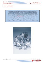
Swirl diffusers OD11 - Pichler
Swirl diffusers OD11 - Pichler
Swirl diffusers OD11 - Pichler

Create successful ePaper yourself
Turn your PDF publications into a flip-book with our unique Google optimized e-Paper software.
Air distribution<br />
Air for<br />
living.
Variable swirl <strong>diffusers</strong><br />
<br />
le swirl diffuser OD-11<br />
Application<br />
<br />
ceiling highs of 3 to 10 m and high induction requirements. It is<br />
suitable for large temperature difference between supply and<br />
room air.<br />
Description<br />
Diffuser is made of housing which has a diffusing funnel mounted<br />
at the bottom. The direction of the discharged air is altered<br />
via the separately adjustable blades. The shape of the diffuser’s<br />
inner part allows “Coanda” effect.<br />
Housing consists of sheet aluminium and blades of pickled sheet<br />
steel. Complete diffuser is powder painted in RAL 9010 or any<br />
colour upon customer’s request.<br />
AI<br />
RAL<br />
9010<br />
M<br />
CD<br />
Individually adjustable blades OD-11<br />
Use of the individually adjustable blades is recommended<br />
when the ventilation system is designed for the specic mode<br />
of operation and the blades can be adjusted during the diffuser<br />
installation.<br />
Variable swirl diffuser OD-11V<br />
Version OD-11V has centrally adjustable blades. Blades can be<br />
manually adjustable or by the means of electric motor installed<br />
on the outer side of the diffuser or by thermostat regulation.<br />
Diffuser is capable of altering discharge direction.<br />
Variable swirl diffuser with the thermostat regulation<br />
OD-11V/TR<br />
OD-11V/TR diffuser has a basic implementation of OD-11V<br />
upgraded thermostatically controlled. Automatic continuous regulation<br />
operates as a function of the temperature of air owing<br />
through the diffuser. ith additional conguration before installation<br />
to ensure optimum operation of the demands of comfort in<br />
the room.<br />
Regulation with the OD-11V/…/RR handle<br />
Regulation with this handle enables manual blade angle adjustment<br />
if the diffuser placement allows acess to the handle. This<br />
type of regulation is suitable for buildings with a lower number<br />
of <strong>diffusers</strong> when the ventilation system is designed for both<br />
summer and winter operation.<br />
1. handle<br />
2. ing screw<br />
1<br />
2<br />
3
OD-11V with the ADT-2 thermostat with analogue output<br />
Description<br />
The ADT-2 differential thermostat with<br />
continuous analogue output is a controller<br />
that, based on the duct air temperature<br />
and room temperature signals, automatically<br />
adjusts the angle of OD-11V blades<br />
as required.<br />
One ADT-2 can operate up to 10 OD-11V<br />
units.<br />
Operation<br />
The controller compares the selected<br />
temperature curve, which is set according<br />
to the OD-11V position, desired mode of<br />
operation, etc, with data received from<br />
temperature sensors located in the air<br />
supply duct and in the room. Taking into<br />
account the desired temperature difference,<br />
the controller generates a continuous<br />
analogue 0-10V DC output signal, which<br />
is then transmitted to the OD-11V electric<br />
motor drive. Comparing the temperature,<br />
the controller automatically recognises<br />
the heating or cooling mode and sets the<br />
OD-11V accordingly. In the case the duct<br />
air temperature is higher than the room<br />
temperature, the controller switches the<br />
OD-11V to the heating mode, i.e. to the<br />
vertical supply of warm air into the room.<br />
In the case the duct air temperature is<br />
lower than the room temperature, the<br />
controller automatically infers that the<br />
system is in the room cooling mode and<br />
accordingly generates a signal to set the<br />
OD-11V to the cooling mode.<br />
Advantage<br />
Applying ADT-2, the need for manual switching<br />
of a large number of OD-11V units<br />
to the proper operational mode is avoided,<br />
since the controller switches the units<br />
automatically. In this way, the efciency of<br />
room air conditioning is enhanced as well.<br />
4<br />
3<br />
T1<br />
ADT-2 differential thermostat<br />
1. controller<br />
2. room temperature sensor<br />
3. duct temperature sensor<br />
4. compact actuator (B3, B6, B9)<br />
1<br />
T1 – air temperature in the duct (°C)<br />
T2 – air temperature in the room (°C)<br />
T1T2: heating – the blade angle is towards 90°<br />
2<br />
T2<br />
4
Variable diffuser with the thermostat regulation OD-11V/TR<br />
Operation<br />
At OD-11V/TR diffuser, centrally adjustable<br />
blades can be adjusted automatically<br />
with the thermostat regulation. Thermostat<br />
perceives temperature of the supply<br />
air and automatically adjusts the blades<br />
angle. No additional power supply and<br />
controls are required, so no additional<br />
wiring installation is needed. Blade angle<br />
according to the supply air temperature is<br />
shown in the chart below.<br />
A hysteresis behavior of the thermostatic<br />
head in both cooling and heating mode<br />
is shown in the chart. After the temperature<br />
is stabilized, angle of the blades is<br />
adjusted to the medium value in about 15<br />
minutes.<br />
AI<br />
RAL<br />
9010<br />
CD<br />
Angle of the blades (˚)<br />
80<br />
75<br />
70<br />
65<br />
60<br />
55<br />
50<br />
45<br />
40<br />
35<br />
30<br />
25<br />
20.0 20.5 21.0 21.5 22.0 22.5 23.0 23.5 24.0 24.5 25.0 25.5 26.0 26.5 27.0 27.5 28.0 28.5 29.0 29.5<br />
Size<br />
OD-11V/TR diffuser can be made in sizes<br />
200, 250, 315, 400, 500, 630 and 800<br />
(sizes 125 and 160 are not available).<br />
Decrease of temperature<br />
Temperature (˚C)<br />
Increase of temperature<br />
Regulation of the initial and nal<br />
blade angle<br />
OD-11V/TR allows the regulation of the<br />
initial and nal blade angle.<br />
During the selection of appropriate<br />
diffuser for certain room conditions with<br />
the Klima ADE software package, exact<br />
angles are calculated according to the<br />
installation height of the diffuser, supplied<br />
air quantity and the temperature difference<br />
between supplied and room temperature.<br />
Calculation is based on air ow speed<br />
of 0.2 m/s in the living area.<br />
Initial blade angle is preadjusted with the<br />
special nut in the range between 30 and<br />
50. Automatic opening of the blades is<br />
initiated, when the temperature reaches<br />
limit value, shown in the chart according<br />
to the preadjusted angle and number of<br />
used spacers. hen initial angle of 45<br />
is preadjusted without additional spacers<br />
and nal angle is 5, blade opening<br />
temperature is between 22.5 and 23 C<br />
(designation 1 in diagram).<br />
Final blade angle is adjusted by adding<br />
spacers below thermostatic head. Default<br />
preassembled spacer allow complete<br />
opening of the blades until 5. By each<br />
added spacer, nal angle is reduced for<br />
5.<br />
Adding of spacers also change the thermostatic<br />
head characteristics (average<br />
values according to the number of added<br />
spacers are shown in the chart).<br />
Angle of the blades (˚)<br />
80<br />
75<br />
70<br />
65<br />
60<br />
55<br />
50<br />
45<br />
40<br />
Mean value<br />
3<br />
35<br />
30<br />
1 2<br />
25<br />
20.0 20.5 21.0 21.5 22.0 22.5 23.0 23.5 24.0 24.5 25.0 25.5 26.0 26.5 27.0 27.5 28.0 28.5 29.0 29.5<br />
Temperature (˚C)<br />
0<br />
1<br />
2<br />
3<br />
4<br />
0 — 1 — 2 — 3 — 4 —<br />
75° 70° 65° 60° 55°<br />
5
Calculation eample of initial and nal blade angle for the OD-11V/TR diffuser<br />
with the Klima ADE 5.4 software package<br />
<br />
Air quantity<br />
Air temperature<br />
Room size<br />
Diffuser size<br />
Calculation<br />
Result of the calculation:<br />
minimum angle in<br />
the cooling mode = 45°<br />
Angle adjustment (designation 2 in diagram):<br />
Result of the calculation:<br />
maximum angle in<br />
the heating mode = 60°<br />
Angle adjustment (designation 3 in diagram):<br />
for 60° three spacers should be used<br />
Summer: cooling<br />
Transitionalperiod: automatic adjustment of blade angle<br />
to the supply air temperature<br />
Winter: heating<br />
6
Dimensions<br />
Size 2 C C1 A ef (m²) f<br />
125 125 205 130 40 0.012<br />
160 160 250 155 40 0.020<br />
200 200 310 174 40 0.030<br />
250 250 400 200 40 0.048<br />
315 315 480 240 40 0.077<br />
400 400 615 265 55 0.125<br />
500 500 790 320 60 0.195<br />
630 630 940 380 80 0.310<br />
800 800 1142 555 75 0.503<br />
Actuator Dispersing gplate<br />
A ef – efective discharge area (m²)<br />
f<br />
Installation of diffuser on a plenum box<br />
1. Plenum box<br />
2. Inlet spigot<br />
3. Dispersing plate<br />
4. Volume control damper M<br />
5. Traverse<br />
6. Diffuser OD-11, OD-11V, OD-11V/TR<br />
7. Adapter<br />
A x A 59<br />
1 2<br />
3<br />
4<br />
5<br />
h1<br />
φ d<br />
H1<br />
Size A H1 h1 A1<br />
125 230 185 112 98 128 205<br />
160 280 210 125 123 163 250<br />
200 325 240 137 158 204 310<br />
250 390 290 167 198 254 400<br />
315 590 325 177 248 319 480<br />
400 590 390 210 313 404 615<br />
500 590 390 210 313 504 790<br />
630 655 530 280 448 634 940<br />
800 1049 630 340 498 804 1142<br />
6<br />
7<br />
φ D<br />
φ A1<br />
40<br />
Round plenum box<br />
1. Plenum box<br />
2. Inlet spigot<br />
3. Suspension bracket<br />
4. Volume control damper M<br />
5. Dispersing plate<br />
6. Diffuser OD-11, OD-11V, OD-11V/TR<br />
φ d<br />
2<br />
4<br />
3<br />
5<br />
1<br />
H1<br />
H<br />
Size H H1 <br />
125 128 250 154 98<br />
160 183 250 166 123<br />
200 204 245 144 158<br />
250 254 285 164 158<br />
315 319 335 189 248<br />
400 404 400 221 313<br />
500 504 400 221 313<br />
630 634 535 289 448<br />
800 804 585 314 498<br />
6<br />
φ D<br />
φ D2<br />
7
Ordering key<br />
OD-11 / P / Z / M / I Size 200<br />
I5 Thermal insulation (PE), thickness 5 mm on the outside of the plenum box<br />
I9 Sound and thermal insulation (from -40 °C to 105 °C) thickness 9 mm on the outside of the plenum box<br />
(the material is synthetic rubber-based)<br />
I19 Sound and thermal insulation (from -40 °C to 105 °C) thickness 19 mm on the outside of the plenum box<br />
(the material is synthetic rubber-based)<br />
M Volume control damper<br />
OK Measuring damper (only in combination with- AR/S-air exhaust round plenum box side entry spigot<br />
and A/S-air exhaust square plenum box side entry spigot)<br />
Z Air supply (square plenum box)<br />
ZR Air supply (round plenum box)<br />
P With dispersing plate*<br />
*Dispenser plate is not installed if the chamber is used for installation.<br />
Ordering key<br />
OD-11 V / P / 1 / Z / M / I Size 200<br />
*Dispenser plate is not installed if the chamber is used for installation.<br />
200 Size (minimum size for OD-11V/TR is 200)<br />
I5 Thermal insulation (PE), thickness 5 mm on the outside of the plenum box<br />
I9 Sound and thermal insulation (from -40 °C to 105 °C) thickness 9 mm on the outside of the plenum<br />
box (the material is synthetic rubber-based)<br />
I19 Sound and thermal insulation (from -40 °C to 105 °C) thickness 19 mm on the outside of the plenum<br />
box (the material is synthetic rubber-based)<br />
M Volume control damper<br />
OK Measuring damper (only in combination with- AR/S-air exhaust round plenum box side entry spigot<br />
and A/S-air exhaust square plenum box side entry spigot)<br />
Z Air supply (square plenum box)<br />
ZR Air supply (round plenum box)<br />
TR Thermostat regulation<br />
R Manual control<br />
RR Manual control with handle on the outside of the diffuser (only for dimensions from 200 to 800)<br />
Actuator driven:<br />
1 Belimo LM 24A<br />
2 Belimo LM 230A<br />
3 Belimo LM 24A-SR<br />
J1 Joventa DAN 1.N<br />
J2 Joventa DAN 2.N<br />
J3 Joventa DMN 1.2N<br />
Actuators for size 630<br />
4 Belimo NM 24A<br />
5 Belimo NM 230A<br />
6 Belimo NM 24A-SR<br />
J4 Joventa DAS 1.N<br />
J5 Joventa DAS 2.N<br />
J6 Joventa DMS 1<br />
Actuators for size 800<br />
Belimo SM 24A<br />
8 Belimo SM 230A<br />
9 Belimo SM 24A-SR<br />
J7 Joventa DA 1<br />
J8 Joventa DA 2<br />
J9 Joventa DM 1.1<br />
P with dispersing plate*<br />
V centrally adjustable<br />
8
Denition of symbols<br />
L<br />
A,B<br />
Q (m³/h) Air flow<br />
x (m) Horizontal distance to the wall<br />
H (m) Room height<br />
H1 (m) Distance from ceiling to occupied<br />
zone<br />
L (m) Throw distance (L=H1+x)<br />
V L (m/s) Air velocity at the throw distance L<br />
t z (K) Temperate difference between the<br />
supply and room air<br />
t L (K) L<br />
Difference between the core and<br />
room air temperature<br />
p t (Pa) Pressure drop<br />
L WA<br />
((A)) Sound power level<br />
V H1 (m/s) Air velocity at the H1 distance<br />
A (m) Distance between <strong>diffusers</strong> by<br />
length and by width<br />
H<br />
Q<br />
t z<br />
V H1<br />
t L<br />
Q<br />
tz<br />
x<br />
H1<br />
L1.8m<br />
V L<br />
t L<br />
Diagram for fast selection<br />
DIAGRAM FAST SELECTION<br />
Corections<br />
In the case of the diffuser installation in<br />
the ceiling, the velocity Vh at the level<br />
A/2+H is to be multiplied with a factor of<br />
1.4 (due to the Coanda effect).<br />
The above applies to the cases of heating<br />
and cooling operation with blade opening<br />
angles less than 30.<br />
OD-11V size 125<br />
OD-11V size 160<br />
OD-11V size 200<br />
OD-11V size 250<br />
OD-11V size 315<br />
Cooling<br />
Heating<br />
Blade angle 45˚<br />
25 - 35 dB(A)<br />
35 - 45 dB(A)<br />
OD-11V size 400<br />
2<br />
OD-11V size 500<br />
1<br />
OD-11V size 630<br />
3<br />
OD-11V size 800<br />
100 200 300 500 1000 2000 3000 5000 8000<br />
Examples for selection 1, 2 and 3: see the following pages.<br />
Diffuser size as a function of distance<br />
between units and effective velocity<br />
800<br />
630<br />
500<br />
400<br />
315<br />
250<br />
200<br />
160<br />
125<br />
20<br />
15<br />
10<br />
7<br />
5<br />
4<br />
3<br />
Recomended size A,B<br />
(m<br />
)<br />
2<br />
10<br />
5<br />
3<br />
2<br />
v ef (m/s)<br />
1<br />
1<br />
0.5<br />
9
Calculation<br />
xampe 1 (i)<br />
Q = 160 m³/h<br />
H = 3 m<br />
H1 = H-1,8 = 3-1,8 = 1,2 m<br />
v H1 = 0,2 m/s<br />
T<br />
T z = -5 K<br />
Recommended size: 125<br />
v ef = Q/(A ef3600) = 160/(0,0123600)<br />
v ef = 3,6 m/s<br />
v H1/v ef = 0,2/3,6 = 0,056<br />
Blade angle: 41°<br />
xampe 1 (heati)<br />
Q = 160 m³/h<br />
H = 3m H1 = 1,2 m<br />
v H1 = 0,2 m/s<br />
T<br />
T z = 10 K<br />
Recommended size: 125<br />
z ΔT<br />
OD-11V 125<br />
COOLING<br />
Blade angle<br />
ΔT<br />
z<br />
0, 6 , 8 1 2<br />
3 , , , , 0 0,15<br />
H1 (m)<br />
v H1 / v ef<br />
HEATING<br />
v ef = 2,7 m/s<br />
Blade angle: 66°<br />
7 6 5 3 2 1 0, ,5<br />
1,0 1,5 2,0 2,5<br />
3<br />
v ef (m/s)<br />
H1 (m)<br />
OD-11V 160<br />
COOLING<br />
Blade angle<br />
∆T<br />
z<br />
∆T<br />
z<br />
HEATING<br />
1 2 3<br />
H1 (m)<br />
0,03 0,04 0,05 0,10 0,15<br />
v H1 / v ef<br />
5 4 3<br />
2<br />
v ef (m/s)<br />
1<br />
0,5<br />
1<br />
1,5 , 3<br />
H1 (m)<br />
10
Blade opening angle during heating and cooling operation<br />
Calculation<br />
OD-11V 200<br />
COOLING<br />
Blade angle<br />
∆T<br />
z<br />
xampe 2 (i)<br />
Q = 350 m³/h<br />
H1 = 1,4 m<br />
v H1 = 0,15 m/s<br />
T<br />
T z = -10 K<br />
Recommended size: 200<br />
v ef = Q/(A ef 3600) = 350/(0,0313600)<br />
v ef = 3,13 m/s<br />
v H1/v ef = 0,15/3,24 = 0,046<br />
Blade angle: 32°<br />
((Blade angle 32° Coanda effect)<br />
H1 = 1,41,4 = 1,96 m<br />
H = H1+1,8 = 1,96+1,8 = 3,67 m<br />
or<br />
H = 1,4 v H1 = 0,151,4 = 0,25 m/s<br />
∆T<br />
z<br />
1 2 3 4 5 6 0,03<br />
HEATING<br />
H1 (m)<br />
0,04 0,05<br />
0,10 0,15<br />
v H1 / v ef<br />
7 6 5 4 3<br />
2<br />
1<br />
2 3 4 5<br />
v ef (m/s)<br />
H1 (m)<br />
6<br />
OD-11V 250<br />
COOLING<br />
Blade angle<br />
ΔT<br />
z<br />
OD-11V 315<br />
COOLING<br />
Blade angle<br />
ΔT<br />
z<br />
-10 K<br />
-15 K<br />
-10 K<br />
-15 K<br />
ΔT<br />
z<br />
+5 K<br />
1 2 3 4 5 6 7 0,03<br />
HEATING<br />
H1 (m)<br />
0,04 0,05 0,10 0,15<br />
v H1<br />
/ v ef<br />
1 2 3 4 5<br />
0,03 0,04 0,05<br />
0,10 0,15<br />
H1 (m) v H1<br />
/ v ef<br />
HEATING<br />
+10 K<br />
ΔT<br />
z<br />
+15 K +5 K<br />
+10 K<br />
+15 K<br />
7 6 5 4 3 2 1 1 2 3 4 5<br />
v ef<br />
(m/s)<br />
H1 (m)<br />
6<br />
10<br />
9 5<br />
4 3<br />
3 4 5 7 8 9 10<br />
v ef<br />
(m/s)<br />
H1 (m)<br />
11
Blade opening angle during heating and cooling operation<br />
OD-11V 400<br />
COOLING<br />
Blade angle<br />
ΔT<br />
z<br />
OD-11V 500<br />
COOLING<br />
Blade angle<br />
ΔT<br />
z<br />
-10 K<br />
-15 K<br />
-10 K<br />
-15 K<br />
ΔT<br />
+10 K<br />
Δ z<br />
+15 K<br />
1 2 3 4 0 0,03 0, 0,05<br />
0,10 0,15<br />
H1 (m)<br />
v H1<br />
/ v ef<br />
HEATING<br />
+5 K<br />
1 2 3 4 5 6 7 8 910<br />
0,03<br />
0,04 0,05 0,10 0,15<br />
H1 (m) v H1<br />
/ v ef<br />
HEATING<br />
ΔT<br />
z +10 K +5 K<br />
+15 K<br />
10 9 8 7 6 5 4 3<br />
2 1 1 3 4<br />
v ef<br />
(m/s)<br />
H1 (m)<br />
5 6<br />
10 9 8 7 6 5 3<br />
2 1 1 3 4<br />
v ef (m/s)<br />
H1 (m)<br />
5<br />
6<br />
Calculation<br />
xampe 3 (i)<br />
Q = 2700 m³/h<br />
v H1 = 0,2 m/s<br />
t z = -10 K<br />
H = 9 m H1 = 9-1,8 = 7,2 m<br />
Recommended size: 630<br />
OD-11V 630<br />
COOLING<br />
Blade angle<br />
ΔT<br />
z<br />
+5 K<br />
+10 K<br />
+15 K<br />
v ef = Q/(Aef3600) = 2700/(0,323600)<br />
v ef = 2,3 m/s<br />
v H1/v ef = 0,2/2,3 = 0,08<br />
Blade angle: 44°<br />
1 3 4 5 6 7 8 910 0,03 0,04 0,05 0,10 0,15<br />
H1 (m)<br />
v H1 / v ef<br />
ΔT HEATING<br />
+15 K +10 K +5 K<br />
Δ z<br />
5<br />
10 9 8 7 6 5 3 2 1 1 3<br />
4 6<br />
v ef (m/s)<br />
H1 (m)<br />
12
f<br />
Blade opening angle during heating and cooling operation<br />
OD-11V 800<br />
COOLING<br />
Blade angle<br />
ΔT<br />
z<br />
1 2 3 4 5 6 7 8 910 0,03 0,04 0,05 0,10 0,15<br />
H1 (m) v H1 / v ef<br />
ΔT<br />
HEATING<br />
z<br />
10 9 8 7 6 5 3 2 1 1 3<br />
4 5 6<br />
v ef (m/s) f<br />
Pressure drops and sound power level<br />
(for version with dispersing plate)<br />
H1 (m)<br />
OD-11V Size 125 - 800<br />
PRESSURE DROPS AND SOUND POWER LEVEL<br />
10<br />
160<br />
200<br />
250<br />
315<br />
400<br />
500<br />
630<br />
7<br />
55<br />
v ef (m/s)<br />
5<br />
4<br />
3<br />
2<br />
800<br />
2<br />
3<br />
25<br />
30<br />
L WA (dB(A))<br />
35<br />
40<br />
45<br />
50<br />
1,5<br />
20<br />
1<br />
100<br />
200 300 400 500 700 1000 1500 2000 3000 5000 7000 10000<br />
1 2 3 4 5 7 10 20 50 100 200<br />
Q (m 3 /h)<br />
Δp t (Pa)<br />
Calculation<br />
xampe 2 (i)<br />
Q = 350 m³/h<br />
L WA = 47 dB(A)<br />
p = 75 Pa<br />
Blade angle: 32°<br />
xampe 3 (i)<br />
Q = 2700 m³/h<br />
L WA = 37 dB(A)<br />
p = 16 Pa<br />
Blade angle: 44°<br />
13
Version: 07/2013<br />
J. PICHLER<br />
Gesellschaft m.b.H.<br />
AUSTRIA<br />
9021 KLAGENFURT<br />
AM WÖRTHERSEE<br />
Karlweg 5<br />
T +43 (0)463 32769<br />
F +43 (0)463 37548<br />
1100 VIENNA<br />
Doerenkampgasse 5<br />
T +43 (0)1 6880988<br />
F +43 (0)1 6880988-13<br />
PICHLER & CO d.o.o.<br />
prezračevalni sistemi<br />
SLOVENIA<br />
2000 MARIBOR<br />
Cesta k Tamu 26<br />
T +386 (0)2 46013-50<br />
F +386 (0)2 46013-55<br />
pichler@pichler.si<br />
www.pichler.si<br />
KLIMA DOP d.o.o.<br />
klimatizacija i ventilacija<br />
SERBIA<br />
11070 NOVI BEOGRAD<br />
Autoput Beograd-Zagreb<br />
bb (Blok 52 – prostor GP<br />
„Novi Kolektiv“)<br />
T +381 (0)11 3190177<br />
F +381 (0)11 3190563<br />
www.klimadop.com<br />
www.pichlerluft.at<br />
14