Nano Letters 13, 2098 - Physik-Institut
Nano Letters 13, 2098 - Physik-Institut
Nano Letters 13, 2098 - Physik-Institut

You also want an ePaper? Increase the reach of your titles
YUMPU automatically turns print PDFs into web optimized ePapers that Google loves.
Letter<br />
pubs.acs.org/<strong>Nano</strong>Lett<br />
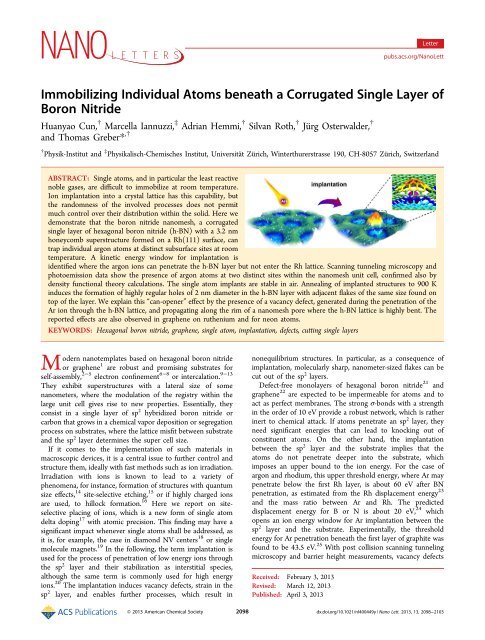
Immobilizing Individual Atoms beneath a Corrugated Single Layer of<br />
Boron Nitride<br />
Huanyao Cun, † Marcella Iannuzzi, ‡ Adrian Hemmi, † Silvan Roth, † Jürg Osterwalder, †<br />
and Thomas Greber* ,†<br />
† <strong>Physik</strong>-<strong>Institut</strong> and ‡ <strong>Physik</strong>alisch-Chemisches <strong>Institut</strong>, Universitaẗ Zürich, Winterthurerstrasse 190, CH-8057 Zürich, Switzerland<br />
ABSTRACT: Single atoms, and in particular the least reactive<br />
noble gases, are difficult to immobilize at room temperature.<br />
Ion implantation into a crystal lattice has this capability, but<br />
the randomness of the involved processes does not permit<br />
much control over their distribution within the solid. Here we<br />
demonstrate that the boron nitride nanomesh, a corrugated<br />
single layer of hexagonal boron nitride (h-BN) with a 3.2 nm<br />
honeycomb superstructure formed on a Rh(111) surface, can<br />
trap individual argon atoms at distinct subsurface sites at room<br />
temperature. A kinetic energy window for implantation is<br />
identified where the argon ions can penetrate the h-BN layer but not enter the Rh lattice. Scanning tunneling microscopy and<br />
photoemission data show the presence of argon atoms at two distinct sites within the nanomesh unit cell, confirmed also by<br />
density functional theory calculations. The single atom implants are stable in air. Annealing of implanted structures to 900 K<br />
induces the formation of highly regular holes of 2 nm diameter in the h-BN layer with adjacent flakes of the same size found on<br />
top of the layer. We explain this “can-opener” effect by the presence of a vacancy defect, generated during the penetration of the<br />
Ar ion through the h-BN lattice, and propagating along the rim of a nanomesh pore where the h-BN lattice is highly bent. The<br />
reported effects are also observed in graphene on ruthenium and for neon atoms.<br />
KEYWORDS: Hexagonal boron nitride, graphene, single atom, implantation, defects, cutting single layers<br />
Modern nanotemplates based on hexagonal boron nitride<br />
or graphene 1 are robust and promising substrates for<br />
self-assembly, 2−5 electron confinement 6−8 or intercalation. 9−<strong>13</strong><br />
They exhibit superstructures with a lateral size of some<br />
nanometers, where the modulation of the registry within the<br />
large unit cell gives rise to new properties. Essentially, they<br />
consist in a single layer of sp 2 hybridized boron nitride or<br />
carbon that grows in a chemical vapor deposition or segregation<br />
process on substrates, where the lattice misfit between substrate<br />
and the sp 2 layer determines the super cell size.<br />
If it comes to the implementation of such materials in<br />
macroscopic devices, it is a central issue to further control and<br />
structure them, ideally with fast methods such as ion irradiation.<br />
Irradiation with ions is known to lead to a variety of<br />
phenomena, for instance, formation of structures with quantum<br />
size effects, 14 site-selective etching, 15 or if highly charged ions<br />
are used, to hillock formation. 16 Here we report on siteselective<br />
placing of ions, which is a new form of single atom<br />
delta doping 17 with atomic precision. This finding may have a<br />
significant impact whenever single atoms shall be addressed, as<br />
it is, for example, the case in diamond NV centers 18 or single<br />
molecule magnets. 19 In the following, the term implantation is<br />
used for the process of penetration of low energy ions through<br />
the sp 2 layer and their stabilization as interstitial species,<br />
although the same term is commonly used for high energy<br />
ions. 20 The implantation induces vacancy defects, strain in the<br />
sp 2 layer, and enables further processes, which result in<br />
nonequilibrium structures. In particular, as a consequence of<br />
implantation, molecularly sharp, nanometer-sized flakes can be<br />
cut out of the sp 2 layers.<br />
Defect-free monolayers of hexagonal boron nitride 21 and<br />
graphene 22 are expected to be impermeable for atoms and to<br />
act as perfect membranes. The strong σ-bonds with a strength<br />
in the order of 10 eV provide a robust network, which is rather<br />
inert to chemical attack. If atoms penetrate an sp 2 layer, they<br />
need significant energies that can lead to knocking out of<br />
constituent atoms. On the other hand, the implantation<br />
between the sp 2 layer and the substrate implies that the<br />
atoms do not penetrate deeper into the substrate, which<br />
imposes an upper bound to the ion energy. For the case of<br />
argon and rhodium, this upper threshold energy, where Ar may<br />
penetrate below the first Rh layer, is about 60 eV after BN<br />
penetration, as estimated from the Rh displacement energy 23<br />
and the mass ratio between Ar and Rh. The predicted<br />
displacement energy for B or N is about 20 eV, 24 which<br />
opens an ion energy window for Ar implantation between the<br />
sp 2 layer and the substrate. Experimentally, the threshold<br />
energy for Ar penetration beneath the first layer of graphite was<br />
found to be 43.5 eV. 25 With post collision scanning tunneling<br />
microscopy and barrier height measurements, vacancy defects<br />
Received: February 3, 20<strong>13</strong><br />
Revised: March 12, 20<strong>13</strong><br />
Published: April 3, 20<strong>13</strong><br />
© 20<strong>13</strong> American Chemical Society <strong>2098</strong> dx.doi.org/10.1021/nl400449y | <strong>Nano</strong> Lett. 20<strong>13</strong>, <strong>13</strong>, <strong>2098</strong>−2103
<strong>Nano</strong> <strong>Letters</strong><br />
Letter<br />
Figure 1. Room-temperature STM data of ion-implanted Ar below the h-BN/Rh(111) nanomesh. (a) Large-area image (104 × 190 nm 2 ) of clean h-<br />
BN/Rh(111), U t = 1.00 V, I t = 0.50 nA. (b) Large-scale image (190 × 190 nm 2 ) with Ar induced protrusions, U t = −1.00 V, I t = 0.50 nA. Without<br />
annealing the sputter charge density of about 250 nC/cm 2 produces 2 × 10 12 protrusions/cm 2 . (c) Zoom-in of panel b (45 × 45 nm 2 ) showing the<br />
selective placing of Ar in wires sites. (d) Statistics based on image panel b, which illustrates the selectivity of the process; Ar stops at two distinct sites<br />
beneath nanomesh wire crossings (WXA and WXB), but not in the pores (P). (e,f) Atomic-resolution STM current (e) and topography (f) images<br />
demonstrating Ar to be implanted beneath the h-BN wires. The bright protrusions are caused by interstitial Ar, and the pink circles indicate vacancy<br />
defects generated by the Ar penetration. The hexagon represents the honeycomb supercell, also shown in the inset of panel d; 11.4 × 11.4 nm 2 , U t =<br />
−1.10 V, I t = 0.10 nA. (g) Cross section along the white line in panel f, the vacancy defect (arrow), an occupied WXB site, a pore and an empty<br />
WXA site are indicated.<br />
due to the penetration and interstitial defects caused by the<br />
implanted atom at rest could be discriminated. 26 However, the<br />
interstitial site of the atoms could not be controlled. If an sp 2<br />
target layer has different bonding sites to the substrate, it can be<br />
expected that superthermal atoms, which penetrate the sp 2<br />
layer, thermalize at specific interstitial sites with a minimal<br />
strain energy.<br />
The scenario of distinct sp 2 bonding sites is achieved with the<br />
h-BN nanomesh. 27 It is a single layer of hexagonal boron nitride<br />
on Rh(111), which forms a corrugated 12 × 12 superstructure<br />
with a lattice constant of 3.2 nm. 28 Because of the misfit<br />
between h-BN and Rh, and the preference of nitrogen to bond<br />
on top of Rh, the <strong>13</strong> × <strong>13</strong> BN units divide into bonding areas,<br />
the “pores” where the h-BN wets the substrate, and into “wires”<br />
where the h-BN has a pure van der Waals bonding to the<br />
substrate.<br />
Figure 1 shows scanning tunneling microscopy data of the<br />
nanomesh before and after exposure to low energy Ar + ions<br />
corresponding to a sputter charge density of 1.6 × 10 12 e/cm 2 .<br />
The protrusions that emerge after ion exposure are situated at<br />
wire crossing sites WX and appear at a tunneling voltage of<br />
2099<br />
−1.1 V with a height of 0.175 ± 0.050 nm above the pore level.<br />
They have a robust signature and may be observed at positive<br />
and negative tunneling voltages. Hence, interstitial defects,<br />
where Ar atoms come to rest below the h-BN and above the<br />
Rh, are located where the nanomesh wires cross. The<br />
nanomesh honeycomb superstructure has two different wire<br />
crossing sites characterized by different registry to the<br />
substrate, 27,28 WXA and WXB. After ion exposure, the two<br />
sites are populated with distinct probabilities. Likely, the WXA/<br />
WXB branching ratio depends on ion beam parameters such as<br />
dose, energy, impact angle, and the annealing temperature. The<br />
selectivity of the implantation process is demonstrated in<br />
Figure 1d. For the large-scale image in Figure 1b, we count 0.2<br />
protrusions per 12 × 12 Rh unit cell, where 54 ± 4% of the Ar<br />
atoms are trapped under WXA sites and no protrusions are<br />
found in the pores. The inset displays the hexagonal<br />
honeycomb super cell of h-BN/Rh(111) with the distinct<br />
regions that differ by the registry, that is, pore (P) and wire<br />
(W).<br />
Figure 1e,f shows the corresponding current and topography<br />
STM images with atomic resolution. Intact h-BN clamps the Ar<br />
dx.doi.org/10.1021/nl400449y | <strong>Nano</strong> Lett. 20<strong>13</strong>, <strong>13</strong>, <strong>2098</strong>−2103
<strong>Nano</strong> <strong>Letters</strong><br />
such that it is fixed at room temperature. In the vicinity of the<br />
Ar protrusions, small defects are observed, which we assign to<br />
the vacancy defects after knock outs during Ar penetration.<br />
Figure 1g displays a line profile in Figure 1f that shows the<br />
height as measured from the bottom of the nanomesh pore.<br />
The cut runs across a defect generated by Ar implantation, a<br />
protrusion on a WXB site, and an area without defects (P) and<br />
in this case empty WXA site. If protrusions are formed, they<br />
also survive exposure to air.<br />
The chemical identification of the implanted species was<br />
performed with X-ray photoelectron spectroscopy (XPS), as<br />
displayed in Figure 2a. The results were compared with STM<br />
Figure 2. Photoemission spectra and corresponding STM images of h-<br />
BN/Ar/Rh(111) before and after annealing to 900 K. (a) Al Kα (ħω<br />
= 1486.6 eV) XPS of Ar 2p core levels for pristine h-BN/Rh(111)<br />
(green, offset 30), Ar implanted (blue, offset 15), and after annealing<br />
(red). The Ar 2p 3/2 binding energy of 241.3 eV shifts by 300 meV<br />
upon annealing, though the intensity is unaltered. (b,c) STM images of<br />
implanted h-BN/Ar/Rh(111) (sputter charge density 1050 nC/cm 2 )<br />
before (b) and after (c) annealing. The bright protrusions in panel b<br />
are due to implanted Ar. After annealing, holes in the nanomesh pores<br />
and bright flakes can be observed (for details see Figure 4); (b) 50 ×<br />
50 nm 2 , U t = −1.00 V, I t = 0.10 nA; (c) 50 × 50 nm 2 , U t = 1.00 V, I t =<br />
1.00 nA. (d) Normal emission UPS (ħω = 21.2 eV) spectra of pristine<br />
h-BN/Rh(111) (green), Ar implanted (blue), and after annealing<br />
(red). The blue spectrum features a distinct broadening and intensity<br />
decrease of the σ α , σ β , π α , and π β bands. All peaks partially recover after<br />
annealing to 900 K.<br />
images of the same preparation. The preparation shown in<br />
Figure 2b has a density of 0.9 protrusions per super cell. On the<br />
other hand, from the XPS atomic ratio of argon and boron, we<br />
determine a coverage of 2.3 Ar atoms per nanomesh super cell.<br />
This indicates that for this relatively large Ar dose the<br />
protrusions may host more than one Ar atom.<br />
The STM image in Figure 2c, which was recorded after<br />
annealing to 900 K, shows that the protrusions disappear,<br />
meanwhile, holes at pore sites and some nearby bright flakes<br />
can be observed on the surface. We interpret these new<br />
2100<br />
Letter<br />
structural features to be due to the “can-opener” effect that is<br />
described below. Intriguingly, XPS indicates no significant<br />
decrease of Ar in the interface, though a 0.3 eV core level<br />
binding energy increase, which rationalizes the disappearance of<br />
the interstitial defects upon ion implantation. Further search<br />
with STM for the Ar that remained in the interface showed<br />
blister-like objects that might house larger amounts of Ar. The<br />
above findings are as well confirmed by angular-resolved<br />
photoelectron spectroscopy (ARUPS), where the h-BN<br />
nanomesh has distinct signatures of the wire- and the poreregion.<br />
27−29 Figure 2d shows the influence of the Ar<br />
implantation on the average valence band structure. The<br />
distinct BN bonding regions are reflected in the splitting of the<br />
σ-bands along the surface normal, 27−29 where the σ α (σ β ) peaks<br />
at 4.2 (5.3) eV indicate hexagonal boron nitride on the wires<br />
(pores). Clearly, implantation of Ar distorts the σ α bands, that<br />
is, the electronic structure in the wire regions and is thus<br />
consistent with the implantation of Ar at WX sites. The Ar dose<br />
is so small that it does not produce a significant Ar 3p level<br />
signature in the ARUPS spectra. If the implanted structure is<br />
annealed to 900 K, also the σ β bands are affected: the σ β<br />
intensity decreases with respect to the pristine mesh, while the<br />
σ α intensity partially recovers.<br />
Density functional theory (DFT) calculations based on the<br />
Gaussian and plane wave (GPW) formalism 30,31 were<br />
performed in order to rationalize the processes induced by Ar<br />
implantation. Different possible sites for the implantation have<br />
been tested by simply positioning an Ar atom between an intact<br />
h-BN layer and Rh and relaxing the structure. It has been found<br />
that beneath the pore the Ar atom is unstable and quickly<br />
moves toward the wire region. Beneath the wire, instead, the Ar<br />
atom can be stabilized at different sites. The differences in<br />
structure and energy are correlated with the registry of BN<br />
units with respect to the three high symmetry sites in the Rh(1<br />
× 1) unit cell. In particular, wire sites with (B-top, N-hcp)<br />
registry are favored with respect to sites with (B-hcp, N-fcc)<br />
registry, which is consistent with the selectivity observed in the<br />
experiments. Hence, we call the former WXA and the latter<br />
WXB wire crossing sites. The presence of one Ar trapped<br />
beneath the wire induces the formation of a BN protrusion,<br />
whose peak is at 0.26 nm from the bottom of the pore. The uplifted<br />
h-BN area involves about one-sixth of nanomesh unit cell.<br />
Figure 3a displays a three-dimensional view of a calculated<br />
structure of the h-BN nanomesh with implanted Ar. We also<br />
investigated the possibility of placing more Ar atoms together<br />
beneath the wire. A few Ar atoms placed in the same area tend<br />
to aggregate and form planar clusters. The larger the cluster, the<br />
higher and broader the protrusion gets. To date we succeeded<br />
to calculate structures with up to 6 Ar atoms per wire crossing.<br />
Figure 3b shows four Tersoff−Hamann simulations 32 of the<br />
h-BN nanomesh, that is, the bare mesh, one Ar at the WXA site,<br />
one Ar at the WXB site, and two Ar atoms at the WXA site.<br />
The maximum height of the simulated STM topography is<br />
about 0.18 nm from the bottom of the pore in the case of one<br />
implanted Ar atom. It increases to more than 0.2 nm for two or<br />
more Ar atoms. The formation of the overlayer protrusion<br />
implies the distortion of h-BN with additional strain in the B−<br />
N bonds and the loss in attractive interaction energy between<br />
BN and Rh. Figure 3c displays the strain-distribution of the 507<br />
B−N bonds in the super cell versus nitrogen atom height for<br />
the four structures in Figure 3b. Strain 0 corresponds to the<br />
calculated equilibrium B−N distance. Nitrogen atoms with a<br />
height above Rh between 0.2 and 0.25 nm belong to the pore.<br />
dx.doi.org/10.1021/nl400449y | <strong>Nano</strong> Lett. 20<strong>13</strong>, <strong>13</strong>, <strong>2098</strong>−2103
<strong>Nano</strong> <strong>Letters</strong><br />
Letter<br />
Figure 3. Density functional theory results on Ar implantation beneath the h-BN nanomesh. (a) Three dimensional view of the h-BN/Ar/Rh(111)<br />
structure with one Ar atom at a WXA wire crossing site. (b) Tersoff−Hamann simulations for four different structures, the bare nanomesh (NM),<br />
one Ar at WXA, one Ar at WXB, and two Ar atoms at WXA. The STM topography has been obtained with a bias potential of −1 eV and for a<br />
density of 10 −4 e/nm 3 . The color scale indicates the height above the topmost Rh layer in nm. (c) Strain of the B−N bonds given in percentual<br />
difference with respect to the calculated equilibrium bond length L 0 ,(L−L 0 )%, versus the height of N atoms above Rh. The four panels correspond<br />
to the four structures in panel b. The inset in the first panel reports the energy increase in meV per bond as calculated by uniformly changing the<br />
bond length of a flat, freestanding h-BN layer. (d) Sorted height of the 169 nitrogen atoms of the NM unit cell. Interstitial Ar lifts about 30 nitrogen<br />
atoms. (e) Implantation energy versus number of Ar atoms in the WXA site. The energy cost per Ar atom decreases by increasing the cluster size,<br />
which predicts Ar clustering.<br />
For the bare nanomesh, some bonds in the pore are slightly<br />
elongated to maximize the contact of N with Rh atoms. In<br />
order to match the 12 × 12 Rh units, the B−N bonds of the<br />
wire are typically contracted. After Ar implantation, many<br />
bonds of the up-lifted area turn out to be longer than in the<br />
bare nanomesh. However, the straining propagates also to<br />
bonds at the rim and in the pore.<br />
Figure 3d shows the nitrogen atom height versus atom<br />
numbers for the four structures in Figure 3c. It can be seen that<br />
more than 30 nitrogen atoms are lifted up by the implantation.<br />
The uplift imposes a global work function shift of 80 meV. This<br />
work function increase is in agreement with experiments in<br />
Figure 2, where an extrapolated shift of 75 meV for one<br />
protrusion per supercell is found.<br />
The total energy differences (implantation energies) with<br />
respect to a pristine nanomesh and an Ar atom in the vacuum<br />
are +2.6 eV (+3.7 eV) for WXA(WXB). Both structures are<br />
metastable and have a local minimum of strain in the substrate<br />
and the sp 2 layer. Figure 3e displays the WXA implantation<br />
energy for clusters of 1−5 Ar atoms. The total amount consists<br />
in compression energy of the Ar, strain-energy of the h-BN<br />
overlayer, strain energy of the substrate and loss in interaction<br />
energy between h-BN and substrate. It can be seen that the<br />
energy stored in the Ar atoms is about 30% of the implantation<br />
energy. The strain energy of the h-BN, which is the energy<br />
difference of the BN layer before and after the implantation, is<br />
in the same order of magnitude. Although the implantation<br />
energies are substantial and call for a hyperthermal process,<br />
they are still smaller than the displacement energy for B and<br />
N. 24 The first implant has to pay most energy, which is related<br />
to its wedge function. This provides a natural explanation for Ar<br />
clustering, mainly on WXA sites, if the temperature allows Ar<br />
diffusion beneath the wires.<br />
Annealing of the implanted structures to 900 K leads to a<br />
peculiar response of the system: the cut-out of h-BN flakes<br />
from the nanomesh pores. Figure 4 shows a h-BN nanomesh<br />
sample exposed to a sputter charge density of 350 nC/cm 2 after<br />
annealing to 900 K. No Ar-related protrusions are visible<br />
anymore, though 2% of the 2 nm pores map dark, and some<br />
bright flakes are visible. In Figure 4a, the flakes display in a<br />
streaky fashion, which is due to dragging of these species by the<br />
STM tip. The zoom-in image in Figure 4b shows that the flakes<br />
lie close to dark pores with matching size. This allows the<br />
conjecture that the flakes correspond to h-BN cut-outs from the<br />
pores (see Figure 4c). The cutting temperature is well below<br />
the h-BN/Rh(111) disintegration at 1160 K. 33 Accordingly, no<br />
2101<br />
dx.doi.org/10.1021/nl400449y | <strong>Nano</strong> Lett. 20<strong>13</strong>, <strong>13</strong>, <strong>2098</strong>−2103
<strong>Nano</strong> <strong>Letters</strong><br />
Figure 4. h-BN nanomesh after annealing of h-BN/Ar/Rh(111) to<br />
900 K (sputter charge density 350 nC/cm 2 ). (a) Large-scale STM<br />
image (180 × 180 nm 2 ) showing 2 nm holes at pore sites. The bright<br />
flakes correspond to the 2 nm cut-outs. The large dark regions are<br />
defects of nanomesh existing prior to ion implantation, U t = −1.10 V,<br />
I t = 0.50 nA. (b) Zoom-in (46 × 46 nm 2 ) of the white frame in panel a<br />
with holes and corresponding flakes. (c) High-resolution image<br />
showing a hole and a flake, 14 × 14 nm 2 , U t = −1.10 V, I t = 0.50 nA.<br />
(d) Cross-sectional profile along the white line in panel c, illustrating<br />
the size of the flake to be larger than the Ar clusters. It also shows the<br />
height difference between the flake and the holes. (e) Sketch of the<br />
can-opener effect. The green pieces represent the “cap”, that is, the h-<br />
BN in the pore. The red-black circle is an active defect that promotes<br />
the cutting of the flake at the rim of the pore. The numbers 1, 2, and 3<br />
indicate the sequence of the process.<br />
such effect is observed, when samples without ion exposure are<br />
annealed to this temperature. Therefore ion exposure must<br />
create an active species that enables cutting (red-black circle in<br />
Figure 4e). Likely the defects due to the Ar implantation<br />
provoke the cutting of h-BN flakes out of the h-BN layer. For<br />
the following reasons we propose this “can-opener” effect to be<br />
related to the migration of the vacancy defects 34 to the<br />
nanomesh rim sites and the straining of the monatomic<br />
membrane upon implantation of Ar atoms. The can-opener<br />
mechanism breaks about 24 B−N bonds at the rim of the<br />
nanomesh pores (step 2 in Figure 4e). The cut pieces are not<br />
anymore bound to the h-BN network, and the relatively weak<br />
bonding to the Rh substrate, which is documented by the<br />
streaky imaging, may break. At 900 K, the cut h-BN flakes from<br />
the pores lift off and diffuse away from the original site (step 3<br />
in Figure 4e). Taking the calculated B−N bond energy in<br />
borazine, the cutting costs 6.3 eV per bond. 35 If hydrogen<br />
assists the cutting effect, that is, if a dangling bond pair is<br />
saturated with hydrogen, the energy cost of 6.3 eV reduces to<br />
0.8 eV, which can be provided by thermal fluctuations at 900 K,<br />
the implantation energy and/or a vacancy defect. Single<br />
interstitial Ar atoms produce strain up to 2% (see Figure 3d),<br />
hence not sufficient for the rupture of the h-BN, which was<br />
found to occur for strain beyond 4% in boron nitride<br />
nanotubes. 36 The high selectivity of the cut must be related<br />
Letter<br />
to the fact that defect creation in sp 2 layers is more facile if the<br />
sheets are bent, as it was found for carbon nanotubes. 37<br />
Control experiments with neon ions also show site-selective<br />
implantation at nanomesh wire crossings and the can-opener<br />
mechanism. For the sister compound graphene on<br />
Ru(0001), 38−40 where the supercell contains as well strongly<br />
bound and a loosely bound regions, 41 we also observe<br />
implantation and the can-opener effect.<br />
In conclusion, the controlled placing of single atoms on<br />
specific sites of a 3 nm honeycomb nanostructure consisting in<br />
one layer of boron nitride on a Rh substrate is reported. At<br />
room temperature, these atoms do not diffuse and remain<br />
protected by an ultimately thin membrane. Furthermore, the<br />
implantation process promotes the can-opener effect, that is,<br />
cutting-out of h-BN flakes with a diameter of 2 nm. This is a<br />
way to functionalize sp 2 layer templates, that is, to produce<br />
anchoring sites for suitable molecular precursors and allows the<br />
immobilization and use of single atoms at room temperature.<br />
The reported effects are robust and quite general: they also<br />
apply for graphene structures.<br />
Methods. Experimental Section. The experiments were<br />
performed in two ultrahigh-vacuum (UHV) systems with base<br />
pressure of 1 × 10 −10 mbar. One is a variable-temperature<br />
scanning tunneling microscope (Omicron VT-STM), and the<br />
other has a room-temperature STM (Park Scientific) combined<br />
with photoemission on the same sample. 9,42 The STM<br />
measurements were carried out with electrochemically etched<br />
tungsten tips. All STM images were taken in constant-current<br />
mode at room temperature. The h-BN nanomesh samples were<br />
produced with the standard recipe, 27 though the samples for<br />
the photoemission experiments were cleaned with Ne + ion<br />
sputtering. The ion implantation was achieved with a Specs<br />
IQP 10/35 Penning type ion sources run at lowest acceleration<br />
potential. The sputter charge density corresponds to the<br />
integrated sputter current density.<br />
Theory. Calculations are performed using Kohn−Sham DFT<br />
within the GPW formalism as implemented in the Quickstep<br />
module in the CP2K program package. 43 Dual-space<br />
pseudopotentials 44 are used to describe the interaction of<br />
valence electrons with atomic cores. The pseudopotentials for<br />
boron and nitrogen assume 3 and 5 valence electrons,<br />
respectively. The atomic cores of the Rh are described by<br />
potentials with 9 valence electrons. The Gaussian basis sets<br />
chosen for this type of application are of the molecularly<br />
optimized type. 45 The PW energy cutoff for the expansion of<br />
the density is set at 500 Ry. The Brillouin zone is sampled only<br />
at the Γ-point. Exchange and correlation are calculated with the<br />
revised Perdew−Burke−Ernzerhof 46 GGA exchange-correlation<br />
functional. The latter is used together with the corrections<br />
for the dispersion interactions. Long-range dispersion interactions<br />
have been computed using DFT-D3 formalisms. 47 We<br />
employ a slablike model where the simulation cell consists of<br />
four layer of 12 × 12 Rh(111) units terminated on one side by<br />
a<strong>13</strong>× <strong>13</strong> h-BN over layer. Periodic boundary conditions are<br />
applied and interactions with periodic images in the direction<br />
perpendicular to the exposed surface are avoided by adding<br />
about 20 Å of vacuum space above the slab. The atoms of<br />
bottom Rh layer are kept fixed in the bulk positions. This<br />
computational setup has been already successfully applied for<br />
several previous studies related to h-BN/Rh(111). <strong>13</strong>,48<br />
2102<br />
dx.doi.org/10.1021/nl400449y | <strong>Nano</strong> Lett. 20<strong>13</strong>, <strong>13</strong>, <strong>2098</strong>−2103
■<strong>Nano</strong> <strong>Letters</strong><br />
AUTHOR INFORMATION<br />
Corresponding Author<br />
*E-mail: greber@physik.uzh.ch. Phone: +41 (0)44 6355744.<br />
Fax: +41 (0)44 6355704.<br />
Notes<br />
The authors declare no competing financial interest.<br />
■ ACKNOWLEDGMENTS<br />
Financial support by the Swiss National Science Foundation is<br />
gratefully acknowledged. The Swiss National Supercomputer<br />
Centre (CSCS) is acknowledged for the generous allocation of<br />
computer time.<br />
■ REFERENCES<br />
(1) Goriachko, A.; Over, H. Int. J. Res. Phys. Chem. Chem. Phys. 2009,<br />
223, 157−168.<br />
(2) N’Diaye, A. T.; Bleikamp, S.; Feibelman, P. J.; Michely, T. Phys.<br />
Rev. Lett. 2006, 97, 215501.<br />
(3) Dil, H.; Lobo-Checa, J.; Laskowski, R.; Blaha, P.; Berner, S.;<br />
Osterwalder, J.; Greber, T. Science 2008, 319, 1824−1826.<br />
(4) Mao, J. H.; Zhang, H. G.; Jiang, Y. H.; Pan, Y.; Gao, M.; Xiao, W.<br />
D.; Gao, H. J. J. Am. Chem. Soc. 2009, <strong>13</strong>1, 14<strong>13</strong>6.<br />
(5) Pollard, A. J.; et al. Angew. Chem. Int. Ed. 2010, 49, 1794−1799.<br />
(6) Zhang, H. G.; Hu, H.; Pan, Y.; Mao, J. H.; Gao, M.; Guo, H. M.;<br />
Du, S. X.; Greber, T.; Gao, H.-J. J. Phys.: Condens. Matter. 2010, 22,<br />
302001.<br />
(7) Borca, B.; Barja, S.; Garnica, M.; Sanchez-Portal, D.; Silkin, V. M.;<br />
Chulkov, E. V.; Hermanns, C. F.; Hinarejos, J. J.; Vazquez de Parga, A.<br />
L.; Arnau, A.; Echenique, P. M.; Miranda, R. Phys. Rev. Lett. 2010, 105,<br />
036804.<br />
(8) Subramaniam, D.; Libisch, F.; Li, Y.; Pauly, C.; Geringer, V.;<br />
Reiter, R.; Mashoff, T.; Liebmann, M.; Burgdörfer, J.; Busse, C.;<br />
Michely, T.; Mazzarello, R.; Pratzer, M.; Morgenstern, M. Phys. Rev.<br />
Lett. 2012, 108, 046801.<br />
(9) Auwarter, W.; Muntwiler, M.; Greber, T.; Osterwalder, J. Surf. Sci.<br />
2002, 511, 379−386.<br />
(10) Sutter, P. W.; Flege, J.-I.; Sutter, E. A. Nat. Mater. 2008, 7, 406−<br />
411.<br />
(11) Preobrajenski, A. B.; Ng, M. L.; Vinogradov, N. A.; Vinogradov,<br />
A. S.; Lundgren, E.; Mikkelsen, A.; Martensson, N. <strong>Nano</strong> Lett. 2009, 9,<br />
2780−2787.<br />
(12) Riedl, C.; Coletti, C.; Iwasaki, T.; Zakharov, A. A.; Starke, U.<br />
Phys. Rev. Lett. 2009, 103, 246804.<br />
(<strong>13</strong>) Brugger, T.; Ma, H.; Iannuzzi, M.; Berner, S.; Winkler, A.;<br />
Hutter, J.; Osterwalder, J.; Greber, T. Angew. Chem. Int. Ed. 2010, 49,<br />
6120−6124.<br />
(14) Schmid, M.; Hebenstreit, W.; Varga, P.; Crampin, S. Phys. Rev.<br />
Lett. 1996, 76, 2298−2301.<br />
(15) Broekmann, P.; Mewe, A.; Wormeester, H.; Poelsema, B. Phys.<br />
Rev. Lett. 2002, 89, 146102.<br />
(16) Aumayr, F.; Facsko, S.; El-Said, A. S.; Trautmann, C.;<br />
Schleberger, M. J. Phys.: Condens. Matter 2011, 23, 393001.<br />
(17) Harris, J. J. Mater. Sci.- Mater. Electron 1993, 4, 93−105.<br />
(18) Gruber, A.; Drabenstedt, A.; Tietz, C.; Fleury, L.; Wrachtrup, J.;<br />
vonBorczyskowski, C. Science 1997, 276, 2012−2014.<br />
(19) Ishikawa, N.; Sugita, M.; Ishikawa, T.; Koshihara, S.; Kaizu, Y. J.<br />
Am. Chem. Soc. 2003, 125, 8694−8695.<br />
(20) Jain, I. P.; Agarwal, G. Surf. Sci. Rep. 2011, 66, 77−172.<br />
(21) Sainsbury, T.; Satti, A.; May, P.; Wang, Z.; McGovern, I.;<br />
Gun’ko, Y. K.; Coleman, J. J. Am. Chem. Soc. 2012, <strong>13</strong>4, 18758−18771.<br />
(22) Bunch, J. S.; Verbridge, S. S.; Alden, J. S.; van der Zande, A. M.;<br />
Parpia, J. M.; Craighead, H. G.; McEuen, P. L. <strong>Nano</strong> Lett. 2008, 8,<br />
2458−2462.<br />
(23) Kosugi, S.; Ishikawa, N.; Saitoh, Y.; Hori, F.; Iwase, A. J. Nucl.<br />
Mater. 2011, 411, 171−173.<br />
(24) Kotakoski, J.; Jin, C. H.; Lehtinen, O.; Suenaga, K.;<br />
Krasheninnikov, A. V. Phys. Rev. B 2010, 82, 1<strong>13</strong>404.<br />
2103<br />
Letter<br />
(25) Marton, D.; Boyd, K.; Lytle, T.; Rabalais, J. Phys. Rev. B 1993,<br />
48, 6757−6766.<br />
(26) Hahn, J.; Kang, H. Phys. Rev. B 1999, 60, 6007−6017.<br />
(27) Corso, M.; Auwärter, W.; Muntwiler, M.; Tamai, A.; Greber, T.;<br />
Osterwalder, J. Science 2004, 303, 217−220.<br />
(28) Berner, S.; Corso, M.; Widmer, R.; Groening, O.; Laskowski, R.;<br />
Blaha, P.; Schwarz, K.; Goriachko, A.; Over, H.; Gsell, S.; Schreck, M.;<br />
Sachdev, H.; Greber, T.; Osterwalder, J. Angew. Chem. Int. Ed. 2007,<br />
46, 5115−5119.<br />
(29) Goriachko, A.; He, Y.; Knapp, M.; Over, H.; Corso, M.; Brugger,<br />
T.; Berner, S.; Osterwalder, J.; Greber, T. Langmuir 2007, 23, 2928−<br />
2931.<br />
(30) Lippert, G.; Hutter, J.; Parrinello, M. Mol. Phys. 1997, 92, 477−<br />
487.<br />
(31) VandeVondele, J.; Krack, M.; Mohamed, F.; Parrinello, M.;<br />
Chassaing, T.; Hutter, J. Comput. Phys. Commun. 2005, 167, 103−128.<br />
(32) Tersoff, J.; Hamann, D. Phys. Rev. B 1985, 31, 805−8<strong>13</strong>.<br />
(33) Dong, G.; Fourre, E. B.; Tabak, F. C.; Frenken, J. W. M. Phys.<br />
Rev. Lett. 2010, 104, 096102.<br />
(34) Zobelli, A.; Ewels, C. P.; Gloter, A.; Seifert, G. Phys. Rev. B 2007,<br />
75, 245402.<br />
(35) Auwarter, W.; Suter, H.; Sachdev, H.; Greber, T. Chem. Mater.<br />
2004, 16, 343−345.<br />
(36) Wei, X.; Wang, M.-S.; Bando, Y.; Golberg, D. Adv. Mater. 2010,<br />
22, 4895.<br />
(37) Lu, A.; Pan, B. Phys. Rev. Lett. 2004, 92, 105504.<br />
(38) Marchini, S.; Guenther, S.; Wintterlin, J. Phys. Rev. B 2007, 76,<br />
075429.<br />
(39) Vazquez de Parga, A. L.; Calleja, F.; Borca, B.; Passeggi, M. C.<br />
G., Jr.; Hinarejos, J. J.; Guinea, F.; Miranda, R. Phys. Rev. Lett. 2008,<br />
100, 056807.<br />
(40) Pan, Y.; Zhang, H.; Shi, D.; Sun, J.; Du, S.; Liu, F.; Gao, H.-J.<br />
Adv. Mater. 2009, 21, 2777.<br />
(41) Brugger, T.; Guenther, S.; Wang, B.; Dil, J. H.; Bocquet, M.-L.;<br />
Osterwalder, J.; Wintterlin, J.; Greber, T. Phys. Rev. B 2009, 79,<br />
045407.<br />
(42) Greber, T.; Raetzo, O.; Kreutz, T.; Schwaller, P.; Deichmann,<br />
W.; Wetli, E.; Osterwalder, J. Rev. Sci. Instrum. 1997, 68, 4549−4554.<br />
(43) CP2k developers group under the terms of the GNU General<br />
Public Licence; see http://www.cp2k.org. 2012.<br />
(44) Goedecker, S.; Teter, M.; Hutter, J. Phys. Rev. B 1996, 54,<br />
1703−1710.<br />
(45) VandeVondele, J.; Hutter, J. J. Chem. Phys. 2007, 127, 114105.<br />
(46) Zhang, Y.; Yang, W. Phys. Rev. Lett. 1998, 80, 890−891.<br />
(47) Grimme, S.; Antony, J.; Ehrlich, S.; Krieg, H. J. Chem. Phys.<br />
2010, <strong>13</strong>2, 154104.<br />
(48) Ding, Y.; Iannuzzi, M.; Hutter, J. J. Phys. Chem. C 2011, 115,<br />
<strong>13</strong>685−<strong>13</strong>692.<br />
dx.doi.org/10.1021/nl400449y | <strong>Nano</strong> Lett. 20<strong>13</strong>, <strong>13</strong>, <strong>2098</strong>−2103