Relaxation Oscillator and One-Shot Using 555 Timer
Relaxation Oscillator and One-Shot Using 555 Timer
Relaxation Oscillator and One-Shot Using 555 Timer

Create successful ePaper yourself
Turn your PDF publications into a flip-book with our unique Google optimized e-Paper software.
<strong>Relaxation</strong> <strong>Oscillator</strong> <strong>and</strong> <strong>One</strong>-<strong>Shot</strong> <strong>Using</strong> <strong>555</strong> <strong>Timer</strong><br />
Physics 116B Lab 11<br />
Rev. 3, January, 2011<br />
Introduction<br />
In this experiment you will use an FET version of a <strong>555</strong> timer (TLC<strong>555</strong>) to<br />
• make a relaxation oscillator (astable multivibrator)<br />
• use the circuit with a thermistor as the timing resistor to make a digital thermometer of sorts (example<br />
of telemetry <strong>and</strong> analog-to-digital conversion) <strong>and</strong><br />
• make a one-shot circuit (monostable multivibrator or timer).<br />
<strong>Relaxation</strong> <strong>Oscillator</strong><br />
Wire the circuit shown in Fig. 1. Note: black dots indicate connections. Lines crossing at right angles<br />
without black dots are not connected. Be sure to use a capacitor with a 10% tolerance for the 0.047 µF<br />
timing capacitor. Use a 10 kΩ resistor for the timing resistor initially. Note that the output is connected to<br />
the trigger <strong>and</strong> threshold inputs through the timing resistor. Examine the circuit <strong>and</strong> convince yourself that<br />
the trigger/threshold level will vary between 1/3 <strong>and</strong> 2/3 of the supply voltage as the output switches from<br />
0 V to a voltage close to the supply voltage <strong>and</strong> back. Observe (<strong>and</strong> copy in your report) the waveforms on<br />
the trigger/threshold node <strong>and</strong> on the output. Record the actual transition voltages at the trigger/threshold<br />
input <strong>and</strong> the high state output voltage. From these measurements <strong>and</strong> your analysis of the circuit, estimate<br />
the period of oscillation. Measure the oscillation frequency using the frequency counter in the Tektronix<br />
function generator <strong>and</strong> compare with what you expect. (Note that the frequency counter is a feature of the<br />
Tektronix function generator, not the pulse generator shown in Fig. 4.)<br />
Digital Thermometer<br />
Now replace the 10 kΩ timing resistor with the thermistor. This is a semiconductor device whose resistance<br />
varies with temperature in a known way. The oscillator frequency readout will now be a measure of the<br />
thermistor temperature. You will observe the frequency to increase if you press the thermistor between<br />
your fingers. Based on the supplied resistance vs. temperature chart, make a chart of expected oscillator<br />
frequency for temperatures between 0 <strong>and</strong> 50 degrees Celsius (in 5 degree steps). If the frequency were read<br />
into a computer, it would be simple to convert it to Celsius for display or recording.<br />
1
Figure 1: <strong>Relaxation</strong> oscillator diagram with thermistor resistance chart.<br />
<strong>One</strong>-<strong>Shot</strong><br />
This circuit (Fig. 2) produces a pulse of known length following a short trigger. The input is normally held<br />
at V DD = 5 V. In this case, the output is 0 V in the stable state. When the input falls below V DD /3 = 1.67 V<br />
due to the trigger pulse, the output goes to 5 V for a period T determined by the RC time constant, then<br />
returns to 0 V.<br />
Build the circuit close to the coaxial connector so signal leads on the board can be kept short to minimize the<br />
effects of wiring inductance <strong>and</strong> capacitance on rapidly rising pulses. Note that the coaxial cable has been<br />
terminated in its characteristic impedance (50 Ω) to prevent reflected waves <strong>and</strong> spurious triggers (not a big<br />
problem here due to the long pulses <strong>and</strong> long time constants). The .01 µF bypass capacitor is connected<br />
between +5 V <strong>and</strong> ground at the chip to absorb voltage <strong>and</strong> current spikes when the output changes rapidly.<br />
The completed circuit is shown in Fig. 3.<br />
Use the Tektronix PG 502 pulse generator (shown in Fig. 4) to produce the desired input pulse. It is probably<br />
easiest to start with a positive going pulse. Begin with the “Complement” button out, rather than in, as<br />
shown in the figure. (“Complement” means applying the logical “NOT” function to the output levels.) The<br />
controls in the top half of the front panel set the pulse width <strong>and</strong> period. Observe the (now positive) pulse by<br />
connecting the Channel 1 oscilloscope probe to the pulse input on the circuit board, as shown in Fig. 3. Set<br />
the oscilloscope to trigger on a positive going signal on Channel 1. The pulse generator width should be set<br />
to 0.5 ms <strong>and</strong> the period should be 100 ms. The high <strong>and</strong> low levels of the pulse are set with the knobs in the<br />
center of the panel. The high level should be 5 V <strong>and</strong> the low level 0 V. Once you have the positive pulse in<br />
good shape, push in the “Complement” button to give the desired falling pulse <strong>and</strong> change the oscilloscope<br />
to trigger on a falling edge on Channel 1. Then you can observe the output simultaneously on Channel 2 to<br />
see if the circuit is functioning properly <strong>and</strong> measure the output pulse width T .<br />
Observe the pulse on the trigger input of the timer <strong>and</strong> sketch it to include in your report. Observe the<br />
2
operation of the timer circuit for timing resistances of 100 kΩ <strong>and</strong> 1.0 MΩ. Measure the output pulse widths<br />
(T in Fig. 2). Analyze the operation of the circuit <strong>and</strong> compare the measured widths with what you expect<br />
from the analysis.<br />
You may also want to try increasing the capacitor value to C = 1 µF with R = 1 MΩ <strong>and</strong> triggering the<br />
circuit manually as shown in the inset of Fig. 2. Observe the output by connecting it to one of the light<br />
emitting diodes on the circuit board.<br />
5 V<br />
0 V<br />
0.5 ms<br />
Tektronix<br />
Pulse<br />
Generator<br />
In<br />
+<br />
<br />
1 k<br />
Push Button<br />
Switch<br />
+5 V<br />
50 coaxial cable<br />
2<br />
Trigger<br />
Manual Trigger Option<br />
R=100 k<br />
C=.047 µF<br />
+/- 10%<br />
Coax termination R T = 50 <br />
(Two 100 1/4 W resistors in parallel)<br />
+5 V<br />
8 4<br />
TLC<strong>555</strong><br />
7<br />
Discharge<br />
6<br />
Threshold<br />
2<br />
Trigger<br />
1<br />
Bypass capacitor<br />
connects between<br />
5 V <strong>and</strong> ground at chip<br />
3<br />
5<br />
.01 µF<br />
Out<br />
.01 µF<br />
T<br />
Figure 2: <strong>One</strong>-shot (timer) circuit. The output pulse width T is proportional to RC.<br />
Figure 3: <strong>One</strong>-shot (timer) circuit as constructed.<br />
3
Figure 4: Tektronix PG502 pulse generator.<br />
4
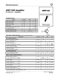
Figure 5: TLC<strong>555</strong> specifications.<br />
5