C. Usha Devi, R. S. Bharat Chandran, R. M. Vasu and A.K. ... - Physics
C. Usha Devi, R. S. Bharat Chandran, R. M. Vasu and A.K. ... - Physics
C. Usha Devi, R. S. Bharat Chandran, R. M. Vasu and A.K. ... - Physics

You also want an ePaper? Increase the reach of your titles
YUMPU automatically turns print PDFs into web optimized ePapers that Google loves.
<strong>Devi</strong> et al.: Mechanical property assessment of tissue-mimicking phantoms…<br />
<strong>and</strong><br />
=<br />
E e <br />
1+1−2 ,<br />
5<br />
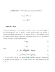
Fig. 2 The schematic diagram of the experimental setup. A<br />
continuous-wave, concave US transducer 1 MHz,withaholeatthe<br />
center of the aperture is used to insonify the phantom. The insonified<br />
focal region is interrogated by an unexp<strong>and</strong>ed laser beam He-Ne,<br />
632.8 nm, which passes coaxially along the transducer axis in a.<br />
The light exiting is collected using a single-mode fiber to a photon<br />
counting PMT single unit consists of a PMT <strong>and</strong> pulse amplifier discriminator<br />
<strong>and</strong> a correlator. b Here the light interrogates the focal<br />
region perpendicular to the axis of the US transducer.<br />
3 Computation of the Displacement Field<br />
in the Focal Region of the Ultrasound<br />
Transducer<br />
In the previous section we have calculated the distribution of<br />
force vector in the focal region of the US transducer. The<br />
force in the focal region is sinusoidal <strong>and</strong> is along the transducer<br />
axis. In this section we use the equilibrium equations of<br />
elasticity to estimate the amplitude of vibration of tissue particles<br />
set in motion by the applied force. For rendering the<br />
computation tractable, the following assumptions are made: 1.<br />
the region of insonification is assumed to be a rectangular slab<br />
inscribed inside the estimated ellipsoidal focal region, <strong>and</strong> 2.<br />
the force distribution is assumed constant in all the voxels in<br />
the slab <strong>and</strong> kept equal to the average force in the ellipsoidal<br />
region.<br />
The governing equation for the tissue displacement<br />
u=u 1 ,u 2 ,u 3 loaded by a vibrating force F 0 cos t along the<br />
transducer axis the transducer axis is taken along the z axis:<br />
Fig 2 is given by 21<br />
u i,jj + + u j,ji = 2 u i<br />
2<br />
= F cos t,<br />
t 4<br />
for i=1,2,3. Here, <strong>and</strong> are the Lame parameters, <strong>and</strong><br />
commas in the subscript denote partial differentiation with<br />
respect to the indices that follow, <strong>and</strong> summation is implied<br />
over repeated indices. The Lame parameters are related to<br />
Young’s modulus E e <strong>and</strong> Poisson’s ratio through<br />
=<br />
E e<br />
21+ .<br />
We compute the displacement suffered by the particles in the<br />
focal volume by solving a 3-D forward elastography problem<br />
using Ansys ANSYS®, Incorporated, Canonsburg, PA. The<br />
object is taken to be a cube of dimensions 101010 mm,<br />
which is meshed using the selected solid element of eight<br />
nodes. The mesh generated has 29,791 nodes to create 27,000<br />
equal volume cubic elements. The boundary conditions are<br />
taken such that it perfectly matches with the experimental<br />
setup, <strong>and</strong> hence the lower surface, the x-z plane, is restricted<br />
from movement. For this, the lower-most plane of the volume<br />
is selected <strong>and</strong> the displacement is given as zero for all degrees<br />
of freedom. Location of the focal point is selected such<br />
that it is at the center of the cube. The acoustic radiation force,<br />
obtained from Sec. 2, is applied to the selected nodes, which<br />
occupy the focal region. The discretized version of the equation<br />
of motion Eq. 4 is then solved using the routines<br />
available with ANSYS.<br />
A typical solution of u=u 1 ,u 2 ,u 3 for the specifications<br />
of the transducer used in the experiments <strong>and</strong> representative<br />
values of E e 11.39 kPa, 0.499, <strong>and</strong> 1000 kg/m 3 <br />
for the phantom is given by u 1 =4.2810 −18 mm,<br />
u 2 =2.5710 −17 mm, <strong>and</strong> u 3 =72.8710 −6 mm.<br />
We underline that the displacement vector is almost along<br />
the transducer axis here in the z direction. This pattern is<br />
repeated when the object parameters are varied to represent a<br />
spectrum of mechanical stiffness. The prior computation is<br />
repeated also for a larger object of dimensions<br />
504515 mm, which also confirmed our observation that<br />
the displacement is along the transducer axis.<br />
In the next section, we describe the interaction of photon<br />
packets launched, both along the transducer axis <strong>and</strong> perpendicular<br />
to it, with the focal region in the object where the<br />
scattering particles are set in motion by the applied force.<br />
4 Interrogation of the Insonified Object<br />
with Light<br />
As seen in the last section, we have set the particles of the<br />
object at the focal region of the US transducer into vibratory<br />
motion through the force applied by the US pressure, which<br />
also produces periodic compression <strong>and</strong> decompression resulting<br />
in the modulation of refractive index. In this section<br />
we interrogate the focal region of the US transducer with a<br />
coherent light beam, so that the phase modulation picked up<br />
by the light can be read out from measurements made at the<br />
boundary. The measurement on the exiting photons is the intensity<br />
autocorrelation g 2 of photons detected through a<br />
photon-counting detector. It is well known 12,13 that the presence<br />
of the ultrasound-tagged photons manifests itself as<br />
modulation on g 2 , whose depth is affected by the optical<br />
absorption coefficient of the insonified region <strong>and</strong> the optical<br />
path length modulation effected by the US beam. We assume<br />
that the set of objects used in our simulations to study the<br />
6<br />
Journal of Biomedical Optics 024028-4<br />
March/April 2007 Vol. 122