Fig. 3-1 Force Table Equipment Force Table Ring and string 4 ...
Fig. 3-1 Force Table Equipment Force Table Ring and string 4 ...
Fig. 3-1 Force Table Equipment Force Table Ring and string 4 ...

You also want an ePaper? Increase the reach of your titles
YUMPU automatically turns print PDFs into web optimized ePapers that Google loves.
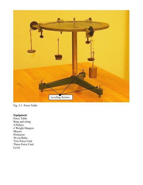
Leveling Screws<br />
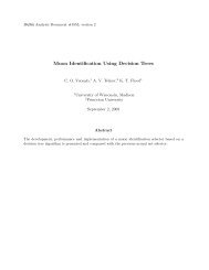
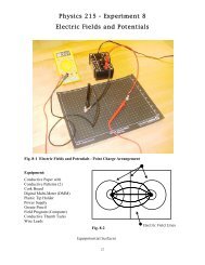
<strong>Fig</strong>. 3-1 <strong>Force</strong> <strong>Table</strong><br />
<strong>Equipment</strong><br />
<strong>Force</strong> <strong>Table</strong><br />
<strong>Ring</strong> <strong>and</strong> <strong>string</strong><br />
4 Pulleys<br />
4 Weight Hangers<br />
Masses<br />
Protractor<br />
30-cm Ruler<br />
Two-<strong>Force</strong> Card<br />
Three-<strong>Force</strong> Card<br />
Level
Experiment 3<br />
Vector Addition<br />
Advance Reading: (Halliday, Resnick <strong>and</strong> Walker) Chapter 3<br />
Objective: The objective of this lab is to study vector addition by three different methods (component<br />
method, graphical method <strong>and</strong> using a force table.)<br />
Theory: Vectors are quantities that have both magnitude <strong>and</strong> direction <strong>and</strong> follow specific rules of<br />
combination. Two of these rules are the commutative <strong>and</strong> associative laws of addition. The graphical<br />
method will be used to verify this rule.<br />
In this lab, a force table will be used to check the graphical <strong>and</strong> component methods of vector<br />
addition. The table is a circular steel table that has the angles 0 o to 360 o inscribed on the edge. (See<br />
<strong>Fig</strong>ure 3-1.) To use the force table, pulleys are placed at the angles specified by the force cards, with<br />
the <strong>string</strong>s attached to the center ring running over the pulleys. Masses are placed on weight hangers<br />
attached to the end of the <strong>string</strong>s to provide the force needed. By adding the vectors, the resultant<br />
vector is found. To balance the force table, however, a force that is equal in magnitude <strong>and</strong> opposite in<br />
direction must counter-balance the resultant. This force is the equilibrant. For example, if a 10 N<br />
force at 0 o <strong>and</strong> a 10 N force at 90 o are added the resultant vector has a magnitude of 14.7 N at 45 o . The<br />
equilibrant has the same magnitude, but the direction is 180 o +45 o =225 o .<br />
Procedure:<br />
Part 1a: Graphical Method- Commutative property of vector addition using two vectors<br />
1. There should be a two-force card <strong>and</strong> a three-force card on your table. Choose the two-force card.<br />
Draw directed line segments for each force. Each should begin at the origin of an x-y axis that has<br />
been drawn at the center of your graph paper. Let 1 cm equal 1 N. Label one vector F 1 <strong>and</strong> the<br />
other F 2 .<br />
2. One lab partner should redraw the vector F 2 at the tip of vector F 1 <strong>and</strong> then draw a line connecting<br />
the origin at the tip of vector F 2 . This line is vector F 1 +F 2 . See <strong>Fig</strong>. 3-2.<br />
The second lab partner should draw the vector F 1 at the tip of vector F 2 <strong>and</strong> then <strong>and</strong> then draw line<br />
connecting the origin at the tip of vector F 1 . This line is also the vector F 2 +F 1 .<br />
Please note in <strong>Fig</strong>. 3-2, the bottom triangle represents F 1 +F 2 , while the top triangle represents<br />
F 2 +F 1 . Thus it can seen that vectors commute when added since the resultant vector is the same<br />
(i.e., F 1 +F 2 = C= F 2 +F 1 ).<br />
3. Measure the angle <strong>and</strong> the magnitude of the resultant vector with the protractor <strong>and</strong> the ruler. Write<br />
down you lab partner’s answer.<br />
A<br />
B<br />
C<br />
B<br />
A<br />
<strong>Fig</strong>. 3-2 A + B = C= B + A
Part 1b: Graphical Method 2 – Associative property of vector addition using three vectors<br />
4. Choose the three-force card <strong>and</strong> draw any one of the three forces from the origin. This is your<br />
starting vector. One lab partner should start with vector F1 (<strong>and</strong> add F2, then F3) . The other lab<br />
partner should start with vector F2<strong>and</strong> add F3 then F1.<br />
5. Select either of the two remaining forces then place it (the 2nd second force chosen) at the tip of<br />
the first. Continue this procedure until all forces are drawn. The resultant is drawn from the origin<br />
to the tip of the last force drawn. Measure the magnitude <strong>and</strong> direction of the resultant. Both lab<br />
partners should have a different polygon, but the same resultant. Write down your lab partner’s<br />
result.<br />
PART 2: Analytical Method<br />
If the direction of a vector is measured from the positive x-axis in a counter-clockwise direction,<br />
(st<strong>and</strong>ard procedure), then the following is true:<br />
F x = F cos θ<br />
F y = F sin θ<br />
θ = tan -1 (F y /F x )<br />
{magnitude of the x-component}<br />
{magnitude of the y-component}<br />
{direction of the vector}<br />
When you add vectors, they yield a resultant, R. To add vectors mathematically, you need to first<br />
determine the x <strong>and</strong> y-components of each vector. F x is the sum of the x-components <strong>and</strong> F y is the<br />
sum of the y-components. Thus<br />
R = F x 2 + F y<br />
2<br />
{magnitude of R}<br />
θ = tan -1 (F y /F x ) {direction of R}<br />
6. Calculate the magnitude <strong>and</strong> direction of R for your forces. Note: Verify that the angle θ is in the<br />
proper quadrant based upon your F x <strong>and</strong> F y . Your calculator will give you only one of two<br />
possible angles (the correct angle or the correct angle plus 180 degrees).<br />
Part 3: <strong>Force</strong> <strong>Table</strong><br />
7. If values from parts one <strong>and</strong> two agree, use the force table to verify these answers. First, level the<br />
force table using the three screws attached to the base of the table <strong>and</strong> the carpenter's level. Place<br />
pulleys at the positions specified by the force card; add masses to provide the forces. Use 100<br />
grams to represent each newton of force. If the values obtained for the resultant are correct, then the<br />
equilibrant will balance the system <strong>and</strong> the ring will be positioned in the middle of the force table.<br />
Add the equilibrant force to the proper position.<br />
8. To determine the uncertainty in the magnitude <strong>and</strong> direction of the equilibrant:<br />
δm - add mass to the equilibrant until the ring shifts, but doesn't touch the pin.<br />
δθ - adjust the position (θ) until the ring shifts, but doesn't touch the pin.<br />
9. Have your instructor pull the pin to check!<br />
Questions:<br />
1. If five vectors were added tail-to-tip <strong>and</strong> they ended up where they started from, what would be the<br />
magnitude <strong>and</strong> direction of R?<br />
2. In this experiment is the graphical method or force table method more accurate? Why?
3. Given 3 vectors A, B <strong>and</strong> C how many different ways of adding these are there? Hint. What is 3! ?<br />
(i.e., What is 3 factorial?) List the different combinations.<br />
4. Did your results ‘verify’ the associative law of addition for vectors. Explain your answer. Be sure<br />
<strong>and</strong> include uncertainties.