This is the title of an example SEG abstract using Microsoft ... - PGS
This is the title of an example SEG abstract using Microsoft ... - PGS
This is the title of an example SEG abstract using Microsoft ... - PGS

You also want an ePaper? Increase the reach of your titles
YUMPU automatically turns print PDFs into web optimized ePapers that Google loves.
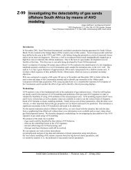
Fiber optic 4C seabed cable field trials<br />
S. Maas*, J. Bunn, B. Bunn, R. Metzbower, J. Bowlus<br />
<strong>an</strong>d J. Bielinski, <strong>PGS</strong> Marine Geophysical<br />
Summary<br />
A fiber optic 4C seabed cable has been successfully<br />
demonstrated in <strong>the</strong> North Sea. The cable design <strong>an</strong>d<br />
perform<strong>an</strong>ce <strong>is</strong> reviewed. A 2400 m cable with 4C sensor<br />
stations located every 25 m was tested in a water depth <strong>of</strong><br />
300 m. While <strong>the</strong> cable tested was limited in se<strong>is</strong>mic<br />
terms, we have demonstrated <strong>the</strong> optical systems<br />
capabilities beyond 3000 m depth <strong>an</strong>d with ch<strong>an</strong>nel counts<br />
in excess <strong>of</strong> 2000 over 12 km in <strong>the</strong> lab. In <strong>the</strong> field trial,<br />
<strong>the</strong> cable was tested along side <strong>an</strong> electrical 4C seabed<br />
cable with comparable results. Data collected from <strong>the</strong> field<br />
tests have proven <strong>the</strong> prototype optical system meets <strong>the</strong><br />
perform<strong>an</strong>ce required <strong>of</strong> <strong>the</strong> deepwater seabed systems.<br />
The optical system <strong>is</strong> <strong>an</strong> excellent fit for conventional 4C<br />
se<strong>is</strong>mic operations <strong>an</strong>d would also be <strong>the</strong> preferred solution<br />
for perm<strong>an</strong>ently installed reservoir monitoring systems.<br />
Introduction<br />
Traditional se<strong>is</strong>mic acqu<strong>is</strong>ition hardware, whe<strong>the</strong>r it be<br />
streamers or 4C seabed systems, rely on sensors that<br />
produce a output voltage that <strong>is</strong> amplified, multiplexed <strong>an</strong>d<br />
tr<strong>an</strong>smitted up a cable to <strong>the</strong> recording system. The passive<br />
nature <strong>of</strong> <strong>the</strong> optical telemetry system eliminates <strong>the</strong> need<br />
for costly in-sea electronics <strong>an</strong>d <strong>the</strong> problems associated<br />
with <strong>the</strong>m, providing a more reliable, less expensive, safer<br />
system to deploy <strong>an</strong>d operate. Optical sensor based<br />
systems are beginning to replace <strong>the</strong> traditional technology<br />
in <strong>the</strong> oil field especially in low ch<strong>an</strong>nel count high stress<br />
environments. The telemetry architecture utilized provides<br />
a system that <strong>is</strong> exp<strong>an</strong>dable beyond <strong>the</strong> capabilities <strong>of</strong><br />
current se<strong>is</strong>mic systems.<br />
Optical sensors used in acquiring se<strong>is</strong>mic data are typically<br />
constructed from optical interferometers. M<strong>an</strong>y<br />
establ<strong>is</strong>hments have demonstrated <strong>the</strong> perform<strong>an</strong>ce <strong>of</strong><br />
optical sensors, with <strong>the</strong> US Naval Research Laboratory<br />
leading <strong>the</strong> technology in <strong>the</strong> late 70s <strong>an</strong>d early 80s;<br />
Giallorenzi (1987) <strong>an</strong>d D<strong>an</strong>dridge et al (1991). Since <strong>the</strong>n<br />
<strong>the</strong> wide spread availability <strong>of</strong> fiber optic components <strong>an</strong>d<br />
subsystems have helped <strong>the</strong> optical sensor evolve <strong>an</strong>d have<br />
made <strong>an</strong> optical sensor system a reality; e.g. Bostick<br />
(2000). In th<strong>is</strong> paper we present <strong>the</strong> seabed system that<br />
was tested in <strong>the</strong> North Sea, we describe <strong>the</strong> cable<br />
construction, <strong>the</strong> optoelectronic system <strong>an</strong>d <strong>the</strong> recording<br />
interface. We also compare <strong>the</strong> data quality between <strong>the</strong><br />
electrical <strong>an</strong>d <strong>the</strong> fiber optic cables.<br />
The fiber optic seabed system<br />
The cable utilizes a Dense Wavelength Div<strong>is</strong>ion<br />
Multiplexing (DWDM) telemetry scheme to optically<br />
power 384 sensors used in <strong>the</strong> in-sea test. An<br />
optoelectronic cabinet was assembled <strong>using</strong> 10 wavelengths<br />
with capability to run 960 ch<strong>an</strong>nels (only 4 wavelengths<br />
were used for <strong>the</strong> demonstration cable). The basics <strong>of</strong> <strong>the</strong><br />
system include a phase modulate laser source passing<br />
through <strong>an</strong> interferometer, where stress from <strong>the</strong> outside<br />
world causes a phase shift in <strong>the</strong> light as it passes through<br />
<strong>the</strong> interferometer. The light <strong>is</strong> <strong>the</strong>n detected <strong>an</strong>d <strong>the</strong> phase<br />
information extracted to output a signal equivalent to <strong>the</strong><br />
input stress.<br />
The sensors<br />
The hydrophone <strong>an</strong>d geophones in each sensor pad were<br />
optical tr<strong>an</strong>sducers fabricated <strong>using</strong> Michelson<br />
interferometers. The hydrophone was <strong>an</strong> air-backed<br />
m<strong>an</strong>drel wound with 55 m <strong>of</strong> optical fiber. The unit was<br />
tested to have a scale factor <strong>of</strong> -140 dB re rad/µPa ±1dB<br />
over environmental pressure <strong>an</strong>d temperature, including<br />
pressures equivalent to 3000 m depth. <strong>Th<strong>is</strong></strong> tr<strong>an</strong>slates into a<br />
no<strong>is</strong>e floor below 1µB. For <strong>the</strong> geophone we used <strong>an</strong> SM-<br />
24 geophone to drive a PZT driven interferometer locally at<br />
<strong>the</strong> geophone. The geophone assembly was a fully<br />
gimbaled 3C sensor <strong>an</strong>d mounted inside a pressure vessel<br />
also capable <strong>of</strong> 3000 m operation.<br />
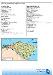
The array construction<br />
The array was designed to be used by a 4C exploration<br />
crew, being continuously deployed <strong>an</strong>d retrieved in<br />
deepwater applications. A steel armored optical cable with<br />
<strong>the</strong> optical fibers inside gel filled stainless steel tubes was<br />
used in <strong>the</strong> construction. A sensor pad was attached to <strong>the</strong><br />
optical cable every 25m, <strong>the</strong> optical fibers in <strong>the</strong> cable were<br />
extracted <strong>an</strong>d fusion spliced to <strong>the</strong> sensors in <strong>the</strong> pad. A<br />
protective cover <strong>an</strong>d bending strain relief was attached to<br />
<strong>the</strong> entire assembly. Mech<strong>an</strong>ical stress test proved <strong>the</strong><br />
cable assemble c<strong>an</strong> be deployed <strong>an</strong>d retrieved thous<strong>an</strong>ds <strong>of</strong><br />
times without damage to <strong>the</strong> optical fiber over loads that<br />
exceed deepwater deployments <strong>of</strong> 3000 m. Figure 1 shows<br />
<strong>the</strong> sensor pad without <strong>the</strong> bending strain relief.
Field Trial <strong>of</strong> a 4C Fiber Optic Seabed System<br />
The optoelectronic cabinet <strong>is</strong> assembled from cardfiles,<br />
were each cardfile contains four laser boards (2 lasers<br />
each), 6 demodulators, one clock reference generator <strong>an</strong>d<br />
<strong>an</strong> interface card. <strong>Th<strong>is</strong></strong> <strong>is</strong> one wavelengths worth <strong>of</strong><br />
processing or 96 optical ch<strong>an</strong>nels. Figure 3 shows <strong>the</strong><br />
cardfile up close <strong>an</strong>d <strong>the</strong> rack used in <strong>the</strong> test. Adding <strong>an</strong><br />
additional cardfile me<strong>an</strong>s you add <strong>an</strong>o<strong>the</strong>r 96 ch<strong>an</strong>nels<br />
worth <strong>of</strong> capability. The optoelectronic system fabricated<br />
actually includes 960 ch<strong>an</strong>nel capability or ten<br />
wavelengths. Only four cardfiles were used to run <strong>the</strong><br />
2400m array<br />
Figure 3: Optoelectronic system cardfile <strong>an</strong>d rack<br />
Figure 1: Sensor pad Assembly, side view <strong>of</strong> geophone ho<strong>using</strong> on<br />
sensor pad base, end on photo with protective ho<strong>using</strong> shows<br />
hydrophone mounted in pad.<br />
The optoelectronic system<br />
The optoelectronic system generates <strong>the</strong> optical power for<br />
<strong>the</strong> array <strong>an</strong>d processes <strong>the</strong> returned optical signals to<br />
extract <strong>the</strong> se<strong>is</strong>mic information. Light returning from <strong>the</strong><br />
array <strong>is</strong> routed to a select group <strong>of</strong> demodulation boards<br />
that process <strong>the</strong> optical data <strong>an</strong>d outputs a 32-bit digital<br />
word equal to <strong>the</strong> se<strong>is</strong>mic data. The data <strong>is</strong> <strong>the</strong>n sent to a<br />
network interface card where it <strong>is</strong> put into data packets <strong>an</strong>d<br />
sent to <strong>the</strong> recording system over <strong>an</strong> ATM network. Figure<br />
2 shows <strong>the</strong> basic optical system architecture.<br />
OPI<br />
Opto-Electronics<br />
Leadin Cable<br />
Field Testing<br />
The field test <strong>of</strong> <strong>the</strong> Seabed array was performed onboard<br />
<strong>the</strong> Bergen Surveyor. The optical array was deployed<br />
parallel to <strong>the</strong> <strong>PGS</strong> FOURcE seabed cable in 300 m <strong>of</strong><br />
water, 20 miles NW <strong>of</strong> Marstein, in <strong>the</strong> Norwegi<strong>an</strong> Trench.<br />
The arrays separation was 50 m <strong>an</strong>d <strong>the</strong> location <strong>of</strong> <strong>the</strong><br />
arrays was monitored <strong>using</strong> external acoustic tr<strong>an</strong>sponders.<br />
The following two figures show <strong>the</strong> optical array during <strong>the</strong><br />
checkout <strong>an</strong>d deployment stages. The data was acquired<br />
while <strong>the</strong> gun boat traveled along <strong>the</strong> arrays firing every 25<br />
meters <strong>an</strong>d again while traversing perpendicular across <strong>the</strong><br />
center <strong>of</strong> <strong>the</strong> arrays.<br />
32 Bit<br />
Data<br />
32 Bit Data<br />
over ATM<br />
PC with <strong>PGS</strong><br />
developed<br />
gAS S<strong>of</strong>tware<br />
PC with Viper<br />
Time series<br />
FFT<br />
Optical Array<br />
IBM 3590<br />
Tape Drive<br />
Figure 2: Optoelectronic system recording interface<br />
Figure 4: Optical seabed array being prepared on floor in Bergen<br />
Warehouse.
Field Trial <strong>of</strong> a 4C Fiber Optic Seabed System<br />
Figure 5: Optical seabed array being prepared for <strong>the</strong> tests, array<br />
on deployment reel <strong>an</strong>d cable being deployed <strong>of</strong>f <strong>the</strong> back deck <strong>of</strong><br />
vessel.<br />
RESULTS<br />
The data shows excellent correlation with that <strong>of</strong> <strong>the</strong><br />
electrical system. Figure 6 <strong>an</strong>d 7 <strong>is</strong> a compar<strong>is</strong>on <strong>of</strong> <strong>the</strong><br />
hydrophones in <strong>the</strong> arrays. The data presented in Figure 6<br />
shows <strong>the</strong> corresponding 96 hydrophone ch<strong>an</strong>nels for <strong>the</strong><br />
electrical <strong>an</strong>d optical arrays for <strong>the</strong> same shot in common<br />
shot-ga<strong>the</strong>rs. Figure 7 <strong>is</strong> <strong>the</strong> averaged signals from a<br />
hydrophone ch<strong>an</strong>nel, <strong>the</strong> red trace <strong>is</strong> <strong>the</strong> electrical ch<strong>an</strong>nel<br />
<strong>an</strong>d green optical. The low frequency spike seen in <strong>the</strong><br />
optical ch<strong>an</strong>nel <strong>is</strong>n’t present in <strong>the</strong> electrical data because<br />
<strong>of</strong> <strong>the</strong> roll <strong>of</strong>f filter used in <strong>the</strong> electrical acqu<strong>is</strong>ition system.<br />
Finally, <strong>the</strong> no<strong>is</strong>e response from <strong>the</strong> two systems <strong>is</strong> shown.<br />
Figure 8 provides <strong>the</strong> same data as seen in 6 & 7 for <strong>the</strong><br />
vertical geophones.<br />
Figure 7: Electrical hydrophones compared to optical hydrophones,<br />
a) average signal output for a sensor (all shots on a line) electrical<br />
(red) <strong>an</strong>d Optical (green), b) average no<strong>is</strong>e response electrical <strong>an</strong>d<br />
optical.<br />
Figure 6: Electrical hydrophones compared to optical hydrophones,<br />
a) shot record for 96 electrical ch<strong>an</strong>nels, b) shot record for 96<br />
optical ch<strong>an</strong>nels<br />
Figure 8: Electrical vertical geophones compared to optical vertical<br />
geophones, a) shot record for 96 electrical ch<strong>an</strong>nels, b) shot record<br />
for 96 optical ch<strong>an</strong>nels, c) average signal output for a sensor (all<br />
shots on a line) electrical (red) <strong>an</strong>d optical (green), d) average<br />
no<strong>is</strong>e electrical (red) <strong>an</strong>d optical.
Field Trial <strong>of</strong> a 4C Fiber Optic Seabed System<br />
Conclusion<br />
We have successfully tested a 2400 m optical seabed cable<br />
in <strong>the</strong> North Sea. A DWDM system allows for <strong>the</strong><br />
exp<strong>an</strong>dability to lengths greater th<strong>an</strong> 12 km with ch<strong>an</strong>nel<br />
counts in excess <strong>of</strong> 2000. The optical cable was tested<br />
along side <strong>an</strong> electrical 4C cable with comparable results.<br />
Data collected from <strong>the</strong> field tests have proven <strong>the</strong><br />
prototype optical system meets <strong>the</strong> perform<strong>an</strong>ce required <strong>of</strong><br />
<strong>the</strong> deepwater seabed systems. The optical system <strong>is</strong> <strong>an</strong><br />
excellent fit for conventional 4C se<strong>is</strong>mic operations <strong>an</strong>d<br />
would also be <strong>the</strong> preferred solution for perm<strong>an</strong>ently<br />
installed reservoir monitoring systems.<br />
References<br />
1) Giallorenzi, “All-optical towed <strong>an</strong>d conformal arrays”,<br />
United States Patent 4,648,083, March 3, 1987<br />
2) D<strong>an</strong>dridge, A. <strong>an</strong>d Cogdell, G., “Fiber Optic Sensors<br />
for Navy Applications”, IEEE LCS, February, 1991.<br />
3) Bostick III, F.X. (Tad), “Field Experimental Results <strong>of</strong><br />
Three-Component Fiber-Optic Se<strong>is</strong>mic Sensors”, <strong>SEG</strong><br />
Exp<strong>an</strong>ded Abstracts, August, 2000<br />
Acknowledgements<br />
We would like to th<strong>an</strong>k <strong>PGS</strong> Marine Acqu<strong>is</strong>ition for <strong>the</strong><br />
support <strong>an</strong>d coordination during <strong>the</strong> tests <strong>an</strong>d <strong>the</strong> crew<br />
onboard <strong>the</strong> Bergen Surveyor for <strong>the</strong>ir excellent efforts.<br />
We also th<strong>an</strong>k <strong>PGS</strong> Marine Geophysical for perm<strong>is</strong>sion to<br />
publ<strong>is</strong>h <strong>the</strong> paper