Type series 920 Master Clock/Signalling Master Clock - Peweta
Type series 920 Master Clock/Signalling Master Clock - Peweta
Type series 920 Master Clock/Signalling Master Clock - Peweta

You also want an ePaper? Increase the reach of your titles
YUMPU automatically turns print PDFs into web optimized ePapers that Google loves.
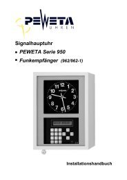
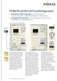
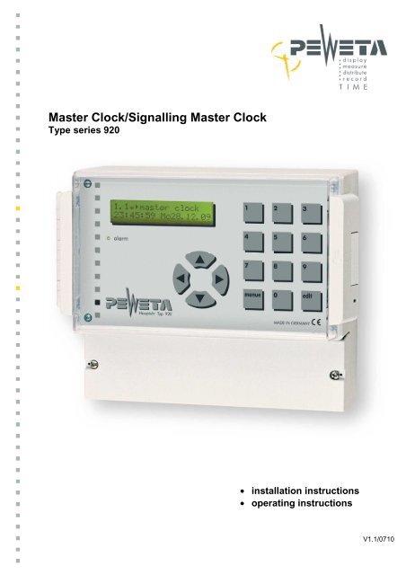
<strong>Master</strong> <strong>Clock</strong>/<strong>Signalling</strong> <strong>Master</strong> <strong>Clock</strong><br />
<strong>Type</strong> <strong>series</strong> <strong>920</strong><br />
• installation instructions<br />
• operating instructions<br />
V1.1/0710
Introduction ......................................................................................................................................... 5<br />
General Remarks ............................................................................................................................................... 5<br />
Electronic Memory .............................................................................................................................................. 5<br />
Radio Control (optionally), DCF77 antenna is an extra (item No. 03.925.111) ................................................. 5<br />
Accuracy without Radio Control ......................................................................................................................... 5<br />
Power Supply/operating voltage ........................................................................................................................ 5<br />
Protective Devices .............................................................................................................................................. 5<br />
Slave <strong>Clock</strong> Line Connections ........................................................................................................................... 5<br />
Power Outage Back-up Batteries ....................................................................................................................... 6<br />
Switch Channels (optionally), in that case we name it <strong>Signalling</strong> <strong>Master</strong> <strong>Clock</strong> ................................................ 6<br />
Multilingual Navigation ....................................................................................................................................... 6<br />
Data Transfer Interface ...................................................................................................................................... 6<br />
<strong>Type</strong>s of <strong>Master</strong> <strong>Clock</strong>s/<strong>Signalling</strong> <strong>Master</strong> <strong>Clock</strong>s, Item numbers, Extras, Options ....................... 7<br />
Safety Rules and Precautions ............................................................................................................ 7<br />
Slave <strong>Clock</strong> Line Checklist ................................................................................................................. 8<br />
Standard version of <strong>Master</strong> <strong>Clock</strong> ..................................................... Fehler! Textmarke nicht definiert.<br />
Mounting the <strong>Master</strong> <strong>Clock</strong> ................................................................................................................. 9<br />
Terminal connections for the full use of all features ...................................................................... 10<br />
Starting (setting up) the <strong>Master</strong> <strong>Clock</strong>, use of menus .................................................................... 11<br />
Structure of the menu table .............................................................................................................................. 11<br />
1. Navigation by "Direct Dialling" .................................................................................................................... 11<br />
2. Navigation with “arrow” keys ...................................................................................................................... 11<br />
Starting Operation ............................................................................................................................. 12<br />
Connecting mains power 230 VAC/50 Hz ........................................................................................................ 12<br />
Switching “on” the <strong>Master</strong> <strong>Clock</strong> (also see menu 1) and set-up .................................................... 13<br />
Connecting a PEWETA DCF77 receiving aerial/antenna ................................................................................ 14<br />
Mounting and aligning the DCF77 receiving aerial/antenna ............................................................................ 14<br />
External power supply for the DCF77 receiving aerial (in very minor applications only) ................................. 14<br />
Connecting a PEWETA GPS receiving aerial (optionally) ............................................................................... 14<br />
Connecting a PEWETA GPS receiving aerial (optionally) ............................................................................... 15<br />
Mounting, positioning and aligning the GPS receiving aerial/antenna ............................................................. 15<br />
Information about the time base ...................................................................................................... 16<br />
Menu 1.5 Test of a continuous GPS radio reception ...................................................................... 16<br />
Test of the latest GPS radio synchronization – “date” ..................................................................................... 16<br />
Test of the latest GPS radio synchronization – “time” ...................................................................................... 16<br />
Test of GPS radio reception quality ................................................................................................................. 16<br />
Connecting one DCF77 receiving aerial (antenna) to two <strong>Master</strong> <strong>Clock</strong>s (<strong>Master</strong>/Submaster) ...................... 17<br />
Synchronising a PEWETA Submaster (2. <strong>Master</strong> <strong>Clock</strong>) by using the PEWETA DCFport24 pulse telegram 17<br />
Connecting the slave clocks to the slave clock lines ..................................................................... 18<br />
Connecting slave clocks with 12/24 V minute pulse movements (mode: minute pulse) ................................. 18<br />
Connecting slave clocks with 24 V minute/second pulse movements (mode: minute/second) ....................... 18<br />
Connecting slave clocks with 24 V second pulse with “creeping” minute (mode: seconds) ............................ 19<br />
Connecting PEWETA slave clocks with DCFport24 pulse telegram movements PW 761 (mode: DCFport24)20<br />
Connecting the Switch Circuits ........................................................................................................ 21<br />
Connecting the RS232 Interface ....................................................................................................... 22<br />
Connecting the Alarm Contact ......................................................................................................... 23<br />
Connecting Option 1 and Option 2 ................................................................................................... 23<br />
Initiate the Operating System, Start-up Menu ................................................................................. 24<br />
Menu 1: <strong>Master</strong> <strong>Clock</strong> ........................................................................................................................ 24<br />
Menu 1.1 <strong>Master</strong> <strong>Clock</strong> ..................................................................................................................... 24<br />
<strong>Master</strong> <strong>Clock</strong> in normal mode (in operation), time and date of the (clock) system .......................................... 24<br />
Menu 1.2 System Time ..................................................................................................................... 24<br />
Setting the time of the clock system manually ................................................................................................. 24<br />
Menu 1.3 System Date ....................................................................................................................... 25<br />
Setting the system date manually .................................................................................................................... 25<br />
Menu 1.4 Setting the time zone ........................................................................................................ 26<br />
Time Zones pre-set (= pre-programmed) in the <strong>Master</strong> <strong>Clock</strong> ........................................................ 27<br />
Menu 1.5 ............................................................................................................................................. 28<br />
Checking the Time Reference .......................................................................................................................... 28<br />
Checking the continuity of DCF77 or GPS radio signal reception ................................................................... 28<br />
- 2 -
Checking the date ............................................................................................................................................ 28<br />
Checking the time ............................................................................................................................................. 28<br />
Checking the quality of the radio signal ........................................................................................................... 29<br />
Menu 1.6 ............................................................................................................................................. 29<br />
Altering the Hours Display (12/24 hrs mode) ................................................................................................... 29<br />
Menu 1.7 ............................................................................................................................................. 30<br />
Altering the Date Display .................................................................................................................................. 30<br />
Menu 2: Slave <strong>Clock</strong> Lines............................................................................................................... 31<br />
Menu 2.1 ............................................................................................................................................. 31<br />
Checking the current drain of slave clock lines ................................................................................................ 31<br />
Menu 2.2 ............................................................................................................................................. 32<br />
Setting the time zone of one or several slave clock line(s) .............................................................................. 32<br />
Menu 2.3 ............................................................................................................................................. 32<br />
Setting the slave clock lines "on" and "off" ....................................................................................................... 32<br />
Menu 2.4 ............................................................................................................................................. 33<br />
Setting the pulse mode..................................................................................................................................... 33<br />
Menu 2.5 ............................................................................................................................................. 34<br />
Setting the update cycle ................................................................................................................................... 34<br />
Menu 2.6 ............................................................................................................................................. 34<br />
Setting the Power Failure Reserve .................................................................................................................. 34<br />
Menu 2.7 ............................................................................................................................................. 35<br />
Adjusting the Time of Slave <strong>Clock</strong> Lines .......................................................................................................... 35<br />
Menu 2.8 ............................................................................................................................................. 36<br />
Setting Pulse Length/Pause ............................................................................................................................. 36<br />
Menu 3: Switching (Switch Channels) ............................................................................................. 37<br />
Menu 3.1 ............................................................................................................................................. 37<br />
Status of Switch Channels ............................................................................................................................... 37<br />
Menu 3.2 ............................................................................................................................................. 37<br />
General procedure for programming switch channels ..................................................................................... 37<br />
Entering a week's program ............................................................................................................... 38<br />
Example 1: "pulse" program for a week ........................................................................................................... 38<br />
Example 2: timed switching "on", once a week ................................................................................................ 39<br />
Example 3: timed switching “off”, once a week ................................................................................................ 39<br />
Programming for a Year .................................................................................................................... 40<br />
Example 3: timed switching "on", once a year ................................................................................................. 40<br />
Example 4: timed switching “off”, once a year ................................................................................................. 41<br />
Example 5: Year program „locked“ .................................................................................................................. 42<br />
Example 6: Year program “unlock” .................................................................................................................. 43<br />
Menu 3.2 ............................................................................................................................................. 44<br />
Delete individual switch instructions (switch times) ......................................................................................... 44<br />
Menu 3.3 ............................................................................................................................................. 44<br />
Delete all switch instructions (switch times) ..................................................................................................... 44<br />
Menu 3.4 ............................................................................................................................................. 45<br />
Manual setting of switch channels (“test”) ........................................................................................................ 45<br />
Menu 4: Reports (= messages) of the System ................................................................................. 46<br />
Menu 4.1 ............................................................................................................................................. 46<br />
Reports (= messages) ...................................................................................................................................... 46<br />
Menu 4.2 ............................................................................................................................................. 46<br />
Edit on messages ............................................................................................................................................. 46<br />
1) Short-circuit on slave clock line(s) ............................................................................................................... 47<br />
2) Overload of single slave clock lines ............................................................................................................ 47<br />
3) Overload of all slave clock lines (complete system) ................................................................................... 47<br />
4) Power failure ............................................................................................................................................... 47<br />
5) Low voltage .................................................................................................................................................. 48<br />
6) Accu empty – system stopped ..................................................................................................................... 48<br />
Menu 5: System ................................................................................................................................. 49<br />
Menu 5.1 ............................................................................................................................................. 49<br />
System ............................................................................................................................................................. 49<br />
Menu 5.2 ............................................................................................................................................. 49<br />
Entering and changing the keyboard code ...................................................................................................... 49<br />
- 3 -
Menu 5.3 ............................................................................................................................................. 50<br />
Display language (= system language) ............................................................................................................ 50<br />
Menu 5.4 ............................................................................................................................................. 51<br />
Time zone, manual entry .................................................................................................................................. 51<br />
Menu 5.5 ............................................................................................................................................. 52<br />
RS232 on/off .................................................................................................................................................... 52<br />
Menu 5.6 ............................................................................................................................................. 53<br />
Access code for the following service menus .................................................................................................. 53<br />
Menu 5.7 ............................................................................................................................................. 53<br />
Initialize system ................................................................................................................................................ 53<br />
Menu 5.8 ............................................................................................................................................. 54<br />
DCF77 statistics ............................................................................................................................................... 54<br />
Menu 5.9 ............................................................................................................................................. 54<br />
Reports of internally measured tensions .......................................................................................................... 54<br />
Menu 6: Options ................................................................................................................................ 55<br />
Menu 6.1 ............................................................................................................................................. 55<br />
Option 1, for example: GPS ............................................................................................................................. 55<br />
Menu 7: Options ................................................................................................................................ 55<br />
Menu 7.1 ............................................................................................................................................. 55<br />
Option 2, for example: RS485 .......................................................................................................................... 55<br />
Technical data ................................................................................................................................... 56<br />
- 4 -
Introduction<br />
General Remarks<br />
This <strong>Master</strong> <strong>Clock</strong> provides a radio controlled time base with either automatic or manual change-over from winter to<br />
summer time (daylight saving) and vice versa. DCF77 (extra) or a GPS antenna (option) is connected.<br />
The <strong>Master</strong> <strong>Clock</strong> is capable of operating and/or controlling secondary devices, such as:<br />
• Analog slave clocks, with or without second hands, also as world time clock system<br />
(for operating second hands a <strong>Master</strong> <strong>Clock</strong> with minimum 2 slave clock lines is obligatory or<br />
230 VAC/50 Hz for operating the second hands, depending on the type of slave clock movement)<br />
• Digital slave clocks, with or without date, also as world time clock system<br />
• Self-adjusting PEWETA DCFport24 telegram slave clocks, analog or digital<br />
• <strong>Signalling</strong> devices, lighting systems etc. (<strong>Master</strong> <strong>Clock</strong> with switch channels optionally)<br />
• IT systems via RS232 interface (programming software is an extra)<br />
Electronic Memory<br />
Electronic memory and automatic update function will, upon return of mains power (e.g. after a mains outage),<br />
immediately readjust all connected clocks to current time.<br />
Radio Control (optionally), DCF77 antenna is an extra (item No. 03.925.111)<br />
The CS2 caesium decay device, operated by the German Federal Institute for Physics and Technology, provides<br />
the official time base for the Federal Republic of Germany (and parts of some neighbouring countries) and<br />
transmits it through the time signal transmitter DCF77, operated by Deutsche Telecom and located at Mainflingen,<br />
near Frankfurt/M. (50° 1' N, 09° 00' E) at 77.5 kHz (long wave/low frequency). The probable time deviation of the<br />
caesium decay device is less than 1 second in 2.6 million years only!<br />
Note: The DCF77 aerial, if provided with the clock (optionally), will receive the time and date signal within a radius<br />
of approx. 2,000 km around Mainflingen and thus synchronise this <strong>Master</strong> <strong>Clock</strong> within this range only, perfect<br />
reception conditions provided. At continuous synchronisation the accuracy of the caesium decay device is<br />
therefore transferred to the <strong>Master</strong> <strong>Clock</strong>. If the <strong>Master</strong> <strong>Clock</strong> will be operated outside this DCF77 reception range<br />
we recommend the <strong>Master</strong> <strong>Clock</strong>’s GPS-version (option suffix -95).<br />
Accuracy without Radio Control<br />
Without DCF77 (or GPS) radio control signal the <strong>Master</strong> <strong>Clock</strong>'s accuracy is reduced to ± 0.1 second/24 h<br />
(measured at 25°C ambient temperature, tolerance to ambient temperature is 0°...40°C.) Changeover of<br />
summer/wintertime (daylight saving) may programmed manually.<br />
Power Supply/operating voltage<br />
Operating power for the <strong>Master</strong> <strong>Clock</strong> is 230 VAC/50 Hz mains.<br />
Protective Devices<br />
The terminal area of the <strong>Master</strong> <strong>Clock</strong> is equipped with several protective devices, e.g. over-voltage protection,<br />
electronic circuit breakers and a fusible link.<br />
Slave <strong>Clock</strong> Line Connections<br />
Each <strong>Master</strong> <strong>Clock</strong> can be equipped with up to four slave clock lines for operating up to 160 single sided slave<br />
clocks (mode: alternating minute pulse 24 V). Power drain for the total of all lines or for individual lines only is<br />
1,000 mA max. at 24 VDC line voltage. Pulse modes available are as follows:<br />
• minute pulse (standard mode)<br />
• half-minute pulse<br />
• second pulse/second pulse with creeping minute<br />
(In second pulse mode total line power is limited to 200 mA max.)<br />
• PEWETA DCFport24 pulse telegram<br />
(In DCFport24 mode total line power is limited to 250 mA max.)<br />
If <strong>Master</strong> <strong>Clock</strong> is equipped with 2 or 4 slave clock lines a parallel operation of even different pulse modes is<br />
possible.<br />
When the <strong>Master</strong> <strong>Clock</strong> reaches its limits of total power output, PEWETA pulse boosting amplifiers (type <strong>series</strong> 930)<br />
are needed for the extension of the master/slave clock system<br />
- 5 -
Power Outage Back-up Batteries<br />
Optional power outage reserve, selectable for each individual slave clock line. A rechargeable NiCd battery,<br />
24 V/0.6 Ah for 24 V lines or 12 V/1.2 Ah for 12 V lines, provides energy for continued (for a limited time period)<br />
operation of all connected clocks in case of a mains power outage (for a limited time period).<br />
Switch Channels (optionally), in that case we name it <strong>Signalling</strong> <strong>Master</strong> <strong>Clock</strong><br />
The <strong>Master</strong> <strong>Clock</strong> can be equipped with up to four switch channels/signalling contacts (2 A/250 V), each<br />
individually programmable for either a week- or a year-program, available to trigger optical and/or acoustic signal<br />
devices which, however, needs separate operating voltage (to be provided at site). Channels may be operated in<br />
mono- or bistable mode (600 timed events max). Manual triggering of each switch channel is possible.<br />
Multilingual Navigation<br />
Multilingual navigation by 7 selectable languages: English, French, Spanish, Portuguese, German, Italian and<br />
Dutch.<br />
Data Transfer Interface<br />
The <strong>Master</strong> <strong>Clock</strong> is equipped with a RS232 data transfer interface, RS485 optionally. Date and time information<br />
is disseminated from this interface to IT users (PCs, SPS etc) for synchronisation. Corresponding software<br />
(PEWETA item No. 05.<strong>920</strong>.000, which is an extra) is obligatory. Additionally, <strong>Master</strong> <strong>Clock</strong> software-updates may<br />
be uploaded through this interface, thus altering the functions of this <strong>Master</strong> <strong>Clock</strong> “in situ” (at site).<br />
- 6 -
<strong>Type</strong>s of <strong>Master</strong> <strong>Clock</strong>s/<strong>Signalling</strong> <strong>Master</strong> <strong>Clock</strong>s, Item numbers, Extras,<br />
Options<br />
<strong>Master</strong> <strong>Clock</strong><br />
Item No.<br />
number of<br />
slave clock<br />
lines<br />
number of<br />
switch<br />
channels<br />
back-up<br />
battery<br />
10.<strong>920</strong>.010 1 0 no<br />
10.<strong>920</strong>.110 1 0 yes<br />
10.<strong>920</strong>.012 1 2 no<br />
10.<strong>920</strong>.112 1 2 yes<br />
10.<strong>920</strong>.014 1 4 no<br />
10.<strong>920</strong>.114 1 4 yes<br />
10.<strong>920</strong>.020 2 0 no<br />
10.<strong>920</strong>.120 2 0 yes<br />
10.<strong>920</strong>.022 2 2 no<br />
10.<strong>920</strong>.122 2 2 yes<br />
10.<strong>920</strong>.024 2 4 no<br />
10.<strong>920</strong>.124 2 4 yes<br />
10.<strong>920</strong>.040 4 0 no<br />
10.<strong>920</strong>.140 4 0 yes<br />
10.<strong>920</strong>.042 4 2 no<br />
10.<strong>920</strong>.142 4 2 yes<br />
10.<strong>920</strong>.044 4 4 no<br />
10.<strong>920</strong>.144 4 4 yes<br />
10.<strong>920</strong>.002 0 2 no<br />
10.<strong>920</strong>.102 0 2 yes<br />
10.<strong>920</strong>.004 0 4 no<br />
10.<strong>920</strong>.104 0 4 yes<br />
Item No.<br />
Extras<br />
03.925.111 DCF77 antenna (IP grade 68)<br />
05.<strong>920</strong>.000 IT-synchronisation software<br />
Options<br />
Opt.-No.<br />
-95 GPS-version incl. GPS antenna<br />
(IP grade 65)<br />
-N.N. RS485 data transfer interface<br />
Safety Rules and Precautions<br />
• Only qualified personnel is authorised to install/to operate the <strong>Master</strong> <strong>Clock</strong> and to open it in case of maintenance.<br />
Unauthorised opening and unqualified repair attempts may cause serious danger to the user. Guarantee will expire.<br />
• This <strong>Master</strong> <strong>Clock</strong> is intended for the control of slave clocks only.<br />
• Is the <strong>Master</strong> <strong>Clock</strong> equipped with switch channels the signalling and switch devices must not be charged with<br />
security functions.<br />
• The connection to mains power must contain a positive separating device such as fusible links, circuit breakers or<br />
switches with a contact separation of 3 mm (1/8") per conductor.<br />
• Maintenance work or wiring changes inside the <strong>Master</strong> <strong>Clock</strong> may only be performed after it is separated from mains.<br />
• The <strong>Master</strong> <strong>Clock</strong> must only be connected to the mains voltage specified on the type label (230 VAC/50 Hz).<br />
• The mains connection must be solid 3-core copper wire of 1.5 mm² minimum cross section.<br />
• Mains power wiring in the building must comply with VDE 0100 or equivalent national or international standards,<br />
according to DIN, ISO or EN.<br />
• During electrical storms cables must neither be connected nor disconnected.<br />
• All voltages connected to the <strong>Master</strong> <strong>Clock</strong> from outside must conform to SELV.<br />
• Both primary and rechargeable batteries must only be replaced by original PEWETA-replacement units of the same<br />
type. Keep batteries and rechargeable batteries clear of fire! Danger of explosion!<br />
• Batteries and rechargeable batteries must not be opened or damaged. The electrolytic liquid inside is poisonous and<br />
may cause damage to skin and eyes.<br />
• Rechargeable batteries may cause injury through electric shock and high currents when short-circuited. Heed the<br />
following precautions when changing rechargeable batteries:<br />
● Do not wear rings, watches or metal bracelets.<br />
● Use tools with insulated handles only.<br />
• Rechargeable batteries must never be short-circuited.<br />
• Rechargeable batteries are classified waste and must be disposed accordingly.<br />
• The <strong>Master</strong> <strong>Clock</strong> must be mounted to a solid surface, no vibrations must be transmitted to the <strong>Master</strong> <strong>Clock</strong>.<br />
• The <strong>Master</strong> <strong>Clock</strong> must not be exposed to direct sunlight. The <strong>Master</strong> <strong>Clock</strong> must always be mounted inside buildings.<br />
• The limits of tolerance to temperature (0°C…40°C) and humidity must not be exceeded.<br />
• The location for mounting the <strong>Master</strong> <strong>Clock</strong> must be chosen to avoid infiltration of dust or moisture.<br />
• The <strong>Master</strong> <strong>Clock</strong> must be kept clear of sources of electro-magnetic interference, such as motors, electric magnets,<br />
choke coils etc.<br />
• The <strong>Master</strong> <strong>Clock</strong> is not cleared for use in areas prone to explosions.<br />
- 7 -
Slave <strong>Clock</strong> Line Checklist<br />
This table may be used to verify the slave clock lines resp. planning your slave clock network. All values<br />
“approx” only.<br />
line<br />
voltage<br />
rated<br />
current<br />
wire cross<br />
section<br />
number<br />
of clocks<br />
max length<br />
of cable<br />
12 V<br />
100 mA<br />
400 mA<br />
1600 mA<br />
0.6 mm 2 10<br />
40<br />
160<br />
226m<br />
56m<br />
13m<br />
12 V<br />
100 mA<br />
400 mA<br />
1600 mA<br />
0.8 mm 2 10<br />
40<br />
160<br />
402m<br />
100m<br />
24m<br />
12 V<br />
100 mA<br />
400 mA<br />
1600 mA<br />
1.4 mm 2 10<br />
40<br />
160<br />
1234m<br />
308m<br />
76m<br />
24 V<br />
60 mA<br />
360 mA<br />
960 mA<br />
0.6 mm 2 10<br />
60<br />
160<br />
906m<br />
150m<br />
56m<br />
24 V<br />
60 mA<br />
360 mA<br />
1000 mA<br />
0.8 mm 2 10<br />
60<br />
160<br />
1612m<br />
268m<br />
100m<br />
24 V<br />
60 mA<br />
360 mA<br />
1000 mA<br />
1.4 mm 2 10<br />
60<br />
160<br />
1234m<br />
802m<br />
308m<br />
A 12V slave clock movement/clockwork will show an interior resistance of 1,000 Ω and draw 12 mA of current.<br />
A 24V slave clock movement/clockwork will show an interior resistance of 4,000 Ω and draw 6 mA of current.<br />
- 8 -
Mounting the <strong>Master</strong> <strong>Clock</strong><br />
1. It is suggested to make use of the template provided with these instructions, mark drilling spots on the wall.<br />
2. Three 5x40 mm screws and three S8 dowels are supplied with the <strong>Master</strong> <strong>Clock</strong>.<br />
3. Using an 8 mm or 5 / 16 " bit, drill three holes. Push dowels in until they are flush with the wall surface.<br />
4. Screw the top screw only into its dowel, leaving a 7 mm ( 5 / 16 ") gap between dowel and screw head. Hook the<br />
lower notch in the bracket on the rear side of the <strong>Master</strong> <strong>Clock</strong> case over the screw head.<br />
5. Unscrew the terminals cover of <strong>Master</strong> <strong>Clock</strong> and fix <strong>Master</strong> <strong>Clock</strong> to wall by using the two remaining screws.<br />
6. Push ends of connecting cables through apertures in the case.<br />
7. Finally place and screw terminals cover.<br />
1. Hook notch on rear side of the<br />
case over screw head.<br />
2. Remove terminals cover and use remaining<br />
two screws to fix <strong>Master</strong> <strong>Clock</strong> safely on the wall.<br />
Finally close the terminals cover.<br />
- 9 -
Terminal connections for the full use of all features<br />
1 Voltage selector (24 V | 0 V | 12 V) for slave clock line(s)<br />
2 Mains power fuse: 5 x 20 mm fusible link, 250 V/500 mA delay (slow blow)<br />
3 Mains power terminals 230 VAC/50 Hz (check with type label)<br />
4 Switch channel terminals/connectors, none to 4 (optionally)<br />
5 RS232 interface<br />
6 DCF77-antenna terminal<br />
7 Slave clock line terminals/connectors, none to 4 (optionally)<br />
8 Alarm terminal<br />
9 Jumper for changing alarm contact from "make" to "break" ("make" is standard)<br />
10 Jumper to set DCF77-antenna power supply "internal" to "external" ("internal" is standard)<br />
11 Terminals/connectors for additional optional features (if these features are enabled, an instruction sheet will<br />
be provided separately)<br />
12 Reset button<br />
13 Rechargeable back-up batteries (optionally) for power outage reserve of slave clock lines<br />
14 LCD socket<br />
15 Keyboard socket<br />
16 LCD contrast adjustment<br />
17 Socket for additional optional function circuit boards, for example GPS-version. If this socket is activated a<br />
separate instruction manual will be provided. Also see menu 6.1.<br />
18 Socket for additional optional function circuit boards, for example RS485. If this socket is activated a separate<br />
instruction manual will be provided. Also see menu 6.2.<br />
- 10 -
Starting (setting up) the <strong>Master</strong> <strong>Clock</strong>, use of menus<br />
Note: During start-up and initiation of software, use of menus and entering of information will be required.<br />
It is advisable to become familiar with the available menus and their use at this time. Please see structure<br />
of menu table:<br />
Structure of the menu table<br />
<strong>Master</strong> <strong>Clock</strong> slave clock lines switch channels messages system option 1 option 2<br />
1.1 <strong>Master</strong> <strong>Clock</strong> 2.1 lines 3.1 switch channels 4.1 messages 5.1 system 6.1 option 1 7.1 option 2<br />
1.2 system time 2.2 time zone 3.2 channel 4.2 messages 5.2 change keycode<br />
1.3 system date 2.3 status 3.3 delete all 5.3 language<br />
1.4 time zone 2.4 mode 3.4 manual 5.4 time zone (man.)<br />
1.5 reference 2.5 cycle 5.5 RS232<br />
1.6 hour mode 2.6 battery 5.6 access<br />
1.7 date mode 2.7 slave time 5.7 initialize<br />
2.8 pulse length 5.8 DCF77 statistics<br />
5.9 measured values<br />
(man.) = manual, by hand<br />
If you are not familiar with the German language you should follow the instructions on page 50 of this<br />
manual first, call up menu 5.3 and change the <strong>Master</strong> <strong>Clock</strong> language (= system language) to English<br />
or 6 other languages, see page 6 (multilingual navigation).<br />
Each individual menu may be accessed in two different ways:<br />
1. Navigation by "Direct Dialling"<br />
Example: For menu 1.2 (system time) press "menue" key, then numeral keys #1 and #2.<br />
Press "menue" key, then numeral keys "1” and “2" for the menu 1.2.<br />
Please try it now, you can’t do something wrong. For menu structure please see<br />
above menu table.<br />
2. Navigation with “arrow” keys<br />
Navigating with the arrow keys ◄▲▼►: By pressing the "right"/"left" and "up"/"down" keys, you can<br />
reach any menu by selecting first its column, then its line. The procedure will be the same in case of<br />
sub-menus. Please try it now, you can’t do something wrong! For menu structure please see above<br />
menu table.<br />
The "edit" key has 2 functions: it is either used<br />
a) to select the function shown in the LCD display or<br />
b) to confirm data entered by preceded key action.<br />
Any key action can, in case of error, be cancelled or interrupted at any time by pressing the "menue"<br />
key.<br />
- 11 -
Connecting mains power 230 VAC/50 Hz<br />
Starting Operation<br />
Unless otherwise specified on the type label, mains power is 230 VAC/50 Hz. Tension relief on the power cable is<br />
to be provided by a conduit as part of the building's installation and responsibility. For safety reasons, connection<br />
of the protective earth (PE) conductor is mandatory, besides, undisturbed DCF77 or GPS radio reception will<br />
only be possible when PE is connected!<br />
The <strong>Master</strong> <strong>Clock</strong> is not equipped with a positive mains separation device, this also is part of the building's<br />
installation and responsibility.<br />
The fuse (5 x 20 mm fusible link, 250 V/500 mA delay) protects the power source by interrupting the L conductor in<br />
case of a short-circuit within the <strong>Master</strong> <strong>Clock</strong>. In this case an error flag "power failure" will be displayed in the front<br />
LCD display of the <strong>Master</strong> <strong>Clock</strong> and the red LED alarm will be “on”!<br />
Connect mains wires to terminals L, N and PE, as shown in the sketch below.<br />
Important! Undisturbed, perfect DCF77 or GPS radio reception will only be possible when protective earth<br />
conductor (PE) is connected!<br />
- 12 -
Switching “on” the <strong>Master</strong> <strong>Clock</strong> (also see menu 1) and set-up<br />
The <strong>Master</strong> <strong>Clock</strong> is switched “on” by setting the mode switch. When delivered, this switch is set in the central<br />
position (the <strong>Master</strong> <strong>Clock</strong> is switched "off"). Switching the <strong>Master</strong> <strong>Clock</strong> "on" also selects the slave clock line<br />
voltage. Sliding the switch to the left, slave clock line voltage will be set to 24 V (standard), sliding the switch<br />
to the right, slave clock line voltage will be 12 V. Check voltage directly at your slave clock movements,<br />
voltage must be identical! Unless 12 V slave clocks have already been installed, slave clock line voltage<br />
should be set to usual 24 V.<br />
Switching the <strong>Master</strong> <strong>Clock</strong> “on” also activates the rechargeable batteries (optionally), enabling the <strong>Master</strong><br />
<strong>Clock</strong>'s full capabilities even without mains power (for a certain period of time only, depending on various<br />
circumstances, mainly on number of connected slave clocks).<br />
Important! If the <strong>Master</strong> <strong>Clock</strong> will be disconnected from mains power for more than 24 hours, the mode switch<br />
must be set to the centre ("off") position. Otherwise the rechargeable batteries will be destroyed by<br />
"deep discharge"!<br />
After the mode switch has been set to either 24 V or 12 V position, the LCD-display of the <strong>Master</strong> <strong>Clock</strong> will<br />
“wake up” and begin to show messages as follows:<br />
<br />
<br />
1.1}><strong>Master</strong> <strong>Clock</strong><br />
00:00:00 So00.00.00<br />
1.1}><strong>Master</strong> <strong>Clock</strong><br />
16:47:04 Fr16.07.10<br />
1.1}><strong>Master</strong> <strong>Clock</strong><br />
16:47:04 Fr16.07.10<br />
Left shown information (blank squares) will be<br />
displayed for about 2 seconds only to test the function<br />
of the LCD display.<br />
Left shown information will be displayed for about 1<br />
second only, afterwards the <strong>Master</strong> <strong>Clock</strong> will shift into<br />
“normal mode” and displays time and date information.<br />
Display in “normal mode”, means “in operation”.<br />
The <strong>Master</strong> <strong>Clock</strong> is now ready for set-up and/or for<br />
the individual adjustments and configurations, see<br />
following menus.<br />
Display in English language.<br />
If you have changed the <strong>Master</strong> <strong>Clock</strong> language from<br />
German to English (menu 5.3), display will be as<br />
shown as left, when <strong>Master</strong> <strong>Clock</strong> is in operation.<br />
The <strong>Master</strong> <strong>Clock</strong> is now operating and ready for configuration to operate the slave clocks and<br />
- if <strong>Master</strong> <strong>Clock</strong> is equipped accordingly - the switch channels (optionally).<br />
- 13 -
Connecting a PEWETA DCF77 receiving aerial/antenna<br />
Connecting a GPS antenna to the <strong>Master</strong> <strong>Clock</strong> proceed to page 15.<br />
Remember: DCF77 radio controlled time code telegrams can only be received in a radius of approx. 2,000<br />
km round Frankfurt/Main! Outside this radius or at insufficient reception conditions we recommend GPS<br />
based version, option suffix -95.<br />
The <strong>Master</strong> <strong>Clock</strong> is prepared for connecting a DCF77 receiving aerial, which is an extra (PEWETA item No.<br />
03.925.111). If this receiving aerial is supplied with the <strong>Master</strong> <strong>Clock</strong> it has to be connected according to the<br />
sketch and table shown hereafter. The DCF77 antenna comes with a 5 m connecting wire. If no suitable position<br />
for mounting the receiving aerial can be found within this range, e.g. in heavily reinforced concrete buildings or<br />
buildings with a façade of corrugated metal sheets, the wire (type LIYCY 4 x 0,25 sqmm) may be extended to<br />
100…150 m.<br />
If DCF77 receiving aerial is connected and orientated properly the <strong>Master</strong> <strong>Clock</strong> will automatically recognise the<br />
incoming DCF77 signal. Make sure that the jumper in the <strong>Master</strong> <strong>Clock</strong> above the DCF77 connecting terminals is<br />
to be set on pins 2/3 to make E 2 = 0 V.<br />
type of wire: LIYCY 4 x 0.25 sqmm<br />
color of wire at<br />
DCF77 antenna<br />
connected to …at<br />
DCF77 antenna<br />
connect to<br />
terminal in<br />
<strong>Master</strong> <strong>Clock</strong><br />
white +UB (7 - 30 volt) +V<br />
green DCF clock (Low active) E1<br />
brown GND (0 volt)<br />
0V<br />
Mounting and aligning the DCF77 receiving aerial/antenna<br />
The light grey plastic case (protection grade IP 68 for in- and outdoors use) of the DCF77 antenna is attached to<br />
one half of a frame-type stainless steel bracket which is flexibly connected to the other half by two screws. The<br />
opposite half of the bracket should be mounted to a wall by two 5x40 mm screws and S 8 dowels supplied with the<br />
antenna kit.<br />
For best possible reception the DCF77 antenna should be mounted in an area free of electromagnetic<br />
interference. Reception is best if either the lid or the bottom surface of the antenna case faces towards<br />
Frankfurt/Main (50° 1’ N, 09° O’ E). Reception of t he DCF77 signal is indicated by a red LED inside the case.<br />
This LED should blink on and off once per second in a steady, stable second-rhythym/cicle, not flicker! At each<br />
59 th second, no signal is transmitted (for reference reasons), so there should be a “one-second-off-interval” in the<br />
blinking sequence once a minute, which is correct.<br />
Find the best mounting position for the DCF77 antenna where this “one-to-one-second” blink cycle is steady. Align<br />
the DCF77 antenna case by turning it on its bracket. If unsuccessful, try a different position. Once you have found<br />
a final position with good reception conditions, fix the antenna and do not move it anymore!<br />
External power supply for the DCF77 receiving aerial (in very minor applications only)<br />
If the DCF77antenna has to be mounted more than 150 m from the <strong>Master</strong> <strong>Clock</strong>, the antenna may be connected<br />
to an external power supply of 7…30 V DC, fed from the building’s installation. In this case only the green and<br />
brown wires of the antenna cable are to be connected to terminals E1 and GND, respectively, at the <strong>Master</strong> <strong>Clock</strong>.<br />
The jumper above the terminals must be changed from pins 2/3 to pins 1/2. The external power supply is to be<br />
connected to +V and 0V at the antenna unit, as shown in the table below.<br />
Connecting a PEWETA GPS<br />
receiving aerial (optionally)<br />
color of wire at<br />
DCF antenna<br />
connected to …at<br />
DCF77 antenna<br />
connect to<br />
terminal at<br />
connect to<br />
…at external<br />
<strong>Master</strong> <strong>Clock</strong> power supply<br />
white +UB (7 - 30 Volt) + V (7 - 30<br />
V)<br />
green DCF Takt (Low aktiv) E1<br />
brown GND (0 Volt) E2 0 V<br />
- 14 -
Connecting a PEWETA GPS receiving aerial (optionally)<br />
If the PEWETA <strong>Master</strong> <strong>Clock</strong> is supplied in GPS-version (PEWETA item No. 10.<strong>920</strong>.xxx or 11.<strong>920</strong>.xxx with option<br />
suffix -95) the <strong>Master</strong> clock is already provided for the connection of the GPS receiving aerial by an integrated<br />
interface card, which has already been installed (see page 10, socket 17) and must not be removed (see menu 6.1).<br />
The GPS receiving aerial itself will be supplied with a wall-plug adapter 230 VAC/50 Hz which has to be connected<br />
as shown in below table. The wire of the GPS receiving aerial has a length of approx. 10 m. If necessary it can be<br />
extended at site up to max. 20 m (wire type LIYCY 4 x 0,25 sqmm). From 20 m to approx. 500 m additional<br />
converters for RS232/RS485 interfaces and vice versa are necessary and are to be provided at site.<br />
connection scheme at <strong>Master</strong> <strong>Clock</strong>:<br />
wire color<br />
GPS antenna<br />
function of GPS<br />
antenna<br />
connection to<br />
<strong>Master</strong> <strong>Clock</strong><br />
yellow TxD E/A 2<br />
green RxD E/A 1<br />
white +4,5 Volt E/A 5<br />
brown GND (0 Volt) GND 3<br />
wire color<br />
wall plug<br />
adapter<br />
function of GPS<br />
antenna<br />
connection to<br />
<strong>Master</strong> <strong>Clock</strong><br />
white + 4,5 V E/A 5<br />
black GND (0 Volt) GND 6<br />
Mounting, positioning and aligning the GPS receiving aerial/antenna<br />
The GPS antenna must in any case be mounted outdoors or next to windows, "free sight to the sky", to find the<br />
satellites. If sufficient mounting place has been found – see menu 1.5, see page 16 – GPS antenna should not be<br />
moved anymore.<br />
Note:<br />
Menu 1.5 of the PEWETA <strong>Master</strong> <strong>Clock</strong> can be used for testing the GPS radio control reception<br />
quality.<br />
Important: The PEWETA <strong>Master</strong> <strong>Clock</strong> in standard will be supplied with time zone based on UTC, not on local<br />
time! Will this <strong>Master</strong> <strong>Clock</strong> be operated in a different time zone than UTC the corresponding local<br />
time zone must be selected in menu 1.4 and menu 2.2 by the operator. Will the corresponding time<br />
zone not be offered in menu 1.4 and 2.2 it can be defined in menu 5.4.<br />
- 15 -
Information about the time base<br />
Menu 1.5 Test of a continuous GPS radio reception<br />
If the PEWETA <strong>Master</strong> <strong>Clock</strong> is supplied as GPS-version (option suffix -95) the <strong>Master</strong> <strong>Clock</strong> will be<br />
synchronized by the worldwide GPS radio signal. The information about the synchronization between <strong>Master</strong><br />
<strong>Clock</strong> and the GPS radio receiving aerial/antenna and the quality of the radio reception is represented in this<br />
menu.<br />
Select menu 1.5 by either using the arrow keys ◄▲▼► or by directly dialling the key combination "menue, 1, 5".<br />
A black square blinks alternately in place of the character you want to enter.<br />
When “menue, 1, 5” is entered display shows:<br />
1.5| <strong>Master</strong> <strong>Clock</strong><br />
reference GPS ” ><br />
A hook (√) shows that the <strong>Master</strong> <strong>Clock</strong> has been<br />
successfully synchronized by the GPS radio signals<br />
within the last 24 hours.<br />
A question mark (?) instead of the hook represents that the <strong>Master</strong> <strong>Clock</strong> has not been successfully synchronized<br />
within the last 24 hours. The current time and date runs on quartz basis only. (If the <strong>Master</strong> <strong>Clock</strong> is a non GPSversion,<br />
means <strong>Master</strong> <strong>Clock</strong> operates on “quartz basis” only, the sign of the question mark is correct). The course<br />
difference in the quartz mode is approx. +/- 0.1 seconds/24 h. In case of summer/wintertime changeover in the<br />
country where the <strong>Master</strong> <strong>Clock</strong> is located the corresponding dates (start, ending) may be manually programmed<br />
(menu: 1.4, 2.2 and 5.4) by the local operator/user.<br />
Test of the latest GPS radio synchronization – “date”<br />
1.5| <strong>Master</strong> <strong>Clock</strong><br />
L.sync. 16.07.10 {<br />
If now arrow key ► is pressed, the submenu radio<br />
synchronization “date” is activated. The display shows the<br />
date at which the master clock has been synchronized<br />
latest. Note: The indicated value corresponds to UTCtime,<br />
not necessarily to local time!<br />
Test of the latest GPS radio synchronization – “time”<br />
1.5| <strong>Master</strong> <strong>Clock</strong><br />
L.sync. 23:59:45 {<br />
By pressing the arrow key ► again the display shows the<br />
time at which the master clock has been synchronized<br />
latest. Note: The indicated value corresponds to UTCtime,<br />
not necessarily to local time!<br />
Test of GPS radio reception quality<br />
By pressing the arrow key ► again the submenu “radio reception quality” is activated.<br />
Black squares in the display show the quality of present GPS reception.<br />
1.5| master clock<br />
receipt -+ <<br />
-+ = good radio reception<br />
- + = sufficient radio reception<br />
- + = bad radio reception, maybe no<br />
synchronization<br />
- + = GPS antenna not connected<br />
Leave the menu by key combination “menue, 1, 1” or by arrow keys ◄▲▼►.<br />
- 16 -
Connecting one DCF77 receiving aerial (antenna) to two <strong>Master</strong> <strong>Clock</strong>s<br />
(<strong>Master</strong>/Submaster)<br />
If two PEWETA <strong>Master</strong> <strong>Clock</strong>s are connected to one DCF77 antenna, their power supplies need to be<br />
decoupled by means of two 1N4001 diodes, as shown below.<br />
Synchronising a PEWETA Submaster (2. <strong>Master</strong> <strong>Clock</strong>) by using the PEWETA DCFport24<br />
pulse telegram<br />
A second PEWETA <strong>Master</strong> <strong>Clock</strong> (Submaster) may be synchronised by using the DCFport24 slave clock line of<br />
the first PEWETA <strong>Master</strong> <strong>Clock</strong>. One slave clock line, e. g. line 1 of first <strong>Master</strong> <strong>Clock</strong> must be set to<br />
DCFport24, see menu 2.4. Terminal A of line 1 in first <strong>Master</strong> <strong>Clock</strong> must be wired to "E1" of second <strong>Master</strong> <strong>Clock</strong><br />
and terminal B of line 1 to "E2" of the second <strong>Master</strong> <strong>Clock</strong>. The jumper above the DCF77 terminals in the<br />
Submaster must be set from position "2/3" to "1/2", see scheme below.<br />
It is even possible to connect several Submaster-<strong>Clock</strong>s to the same slave clock line of the first <strong>Master</strong> <strong>Clock</strong>.<br />
- 17 -
Connecting the slave clocks to the slave clock lines<br />
Note: After having set the <strong>Master</strong> <strong>Clock</strong> to its operating status (see page 13) you will find following standard<br />
parameters in the corresponding menus:<br />
menu 2.2 time zone: CET/CEST<br />
menu 2.3 status: Status off<br />
menu 2.4 mode: minute<br />
menu 2.5 cycle: 12 hours<br />
menu 2.6 battery: on (if equipped with back-up batteries for the slave clock lines)<br />
menu 2.7 slave time: arbitrary, random time<br />
menu 2.8 pulse length: 1 second (1.0 s)<br />
Please decide whether you want to accept this parameter status, (especially menu 2.2 time zone!!), otherwise you<br />
have to change it, please see the corresponding menus on following pages.<br />
Connecting slave clocks with 12/24 V minute pulse movements (mode: minute pulse)<br />
1. Wire (=connect) all minute pulse slave clocks you want to “address” to one slave clock line in parallel to the<br />
corresponding slave clock line terminals in the <strong>Master</strong> <strong>Clock</strong>. Decide whether all slave clocks of your<br />
master/slave clock system shall be connected (=addressed) to 1 slave clock line only or to 2, 3 or 4 slave clock<br />
lines (if <strong>Master</strong> <strong>Clock</strong> is equipped accordingly).<br />
1. Set each of your slave clocks of each line manually (by hand) to an arbitrarily selected but uniform (!) time,<br />
for example all slave clocks exactly on 12:00 hours position.<br />
3. Provided pulse mode in menu 2.4 is set to “minutes”…<br />
4. ..now exactly enter your arbitrarily selected slave clock time (in our example 12:00) in menu 2.7 (12:00:--).<br />
5. Check again all parameters of above mentioned menus 2.2 to 2.8 are set according to your individual<br />
requirements.<br />
6. Now set the line(s) to “status on” in menu 2.3. All correctly connected slave clocks of the corresponding<br />
line(s) will now move automatically to the present local time, provided you have selected one of the offered<br />
time zones/city names or manually entered the local time as well in menu 1.4 for the <strong>Master</strong> <strong>Clock</strong> and in<br />
menu 2.2 “manually” for your slave clock line(s).<br />
7. If the one or other slave clock (or one side of a double sided clock) lags exactly 1 minute behind the set time<br />
after the move-up is completed, reverse polarity at the corresponding slave clock movement by inverting the<br />
two-pin connector and carefully manually (by hand) advance the slave clock by this 1 missing minute, see<br />
page 19. Also see installation instruction sheet for slave clock movement (coming with each PEWETA slave<br />
clock), item No. PEWETA B 602100-811, -821, -822, 825 and -826.<br />
Connecting slave clocks with 24 V minute/second pulse movements (mode:<br />
minute/second)<br />
1. A <strong>Master</strong> <strong>Clock</strong> with minimum 2 slave clock line terminals is obligatory.<br />
2. One line (for example line 1) has to be defined as “minutes” pulse mode in menu 2.4.<br />
3. A second line (for example line 2) has to be defined as “seconds” pulse mode in menu 2.4.<br />
4. Important: “60 seconds” has to be entered/selected for the required cycle of line 2 in menu 2.5.<br />
5. Wire (=connect) all “minute” pulse mode connectors of the slave clock movements in parallel to the slave<br />
clock line terminals defined as “minute” pulse (in our example line 1).<br />
6.) Wire/connect all “second” pulse mode connectors of the slave clock movements in parallel to the slave clock<br />
line terminals defined as “second” pulse mode (in our example line 2).<br />
7. Set each of your slave clocks of this line manually (by hand) to an arbitrarily but uniform (!) time, for example<br />
all slave clocks exactly on 12:00:00 hours position. Again, make sure that all 3 hands (h/m/s) are exactly<br />
positioned on 12:00:00.<br />
- 18 -
8. Provided pulse mode of line 1 is set to “minutes”, pulse mode of line 2 is set to “seconds” in menu 2.4 and<br />
“60 seconds” for line 2 is set in menu 2.5…<br />
9. ..now exactly enter your arbitrarily selected slave clock time (in our example 12:00:00) in menu 2.7:<br />
12:00:-- for hour and minute in line 1, --:--:00 for the seconds in line 2.<br />
10. Check again, all parameters of above mentioned menus 2.2 to 2.8 are set according to your individual<br />
requirements.<br />
11. Now set the lines (in our example first line 1, then line 2) to “status on” in menu 2.3 status. All correctly<br />
connected slave clocks of the corresponding line(s) will now move automatically to the present local time,<br />
provided you have selected one of the offered time zones/city names or manually entered the local time as<br />
well in menu 1.4 for the <strong>Master</strong> <strong>Clock</strong> and in menu 2.2 “manually” for your slave clock line(s).<br />
12. If at the one or other slave clock (or one side of a double sided clock) the minute hand lags exactly 1<br />
minute and/or the second hand lags exactly 1 second behind the set time after the move-up is completed,<br />
reverse polarity at the corresponding slave clock movement(s) either<br />
● by inverting the corresponding “minute” or “second” two-pin connector or<br />
● by drawing the corresponding minute or second connector from position AB to BA (or vice-versa),<br />
see below pictures. Manually (by hand) advance the slave clock by this missing 1 minute resp. 1 second.<br />
For additional information please also see corresponding installation instruction sheet PEWETA for slave<br />
clock movement (coming with each slave clock), for example PEWETA item No. 183.042, 183.224.<br />
changing the polarity<br />
changing the polarity<br />
Connecting slave clocks with 24 V second pulse with “creeping” minute (mode:<br />
seconds)<br />
1. One slave clock line of your choice has to be defined as “seconds” pulse mode in menu 2.4.<br />
2. In menu 2.5 cycles “12 hrs.” has to be entered/selected for this selected line.<br />
3. Wire (=connect) all “seconds” pulse mode connectors of the slave clock movement to this slave clock line.<br />
4. Set each of your slave clocks of this line manually (by hand) to an arbitrarily selected but uniform (!) time.<br />
Note: Ideally the selected slave clock time should be shortly before the actual/present time (= time of the<br />
<strong>Master</strong> <strong>Clock</strong>),as with a too big (=long) time difference it may happen that due to construction this type of slave<br />
clock movements will “wait” for a period of approx. 22 hours before clocks will be adjusted!<br />
5. Now exactly enter your arbitrarily selected slave clock time (hh:mm:ss) in menu 2.7.<br />
6. Set the line to “status on” in menu 2.3 status. All correctly connected slave clocks of this line will now move<br />
automatically to the present local time (=time of the <strong>Master</strong> <strong>Clock</strong>), provided you have selected one of the<br />
offered time zones/city names or manually entered the local time as well in menu 1.4 for the <strong>Master</strong> <strong>Clock</strong><br />
and in menu 2.2 “manually” for this slave clock line.<br />
- 19 -
7. If the one or other slave clock (or one side of a double sided clock) lags exactly 1 second behind the set<br />
time after the move-up is completed, reverse polarity at the corresponding slave clock movement either by<br />
inverting the corresponding connector (or according to movement construction of other movement brands<br />
manufacturers) and manually (by hand) advance the slave clock by this missing 1 second. For additional<br />
information please also see installation instruction sheet for slave clock movement (coming with each<br />
PEWETA slave clock).<br />
Connecting PEWETA slave clocks with DCFport24 pulse telegram movements PW 761<br />
(mode: DCFport24)<br />
Important: Position of hands (h/m/s) of all PEWETA DCFport24 pulse telegram slave clocks, whether<br />
connected or not, have to be ignored! They will be adjusted automatically!<br />
1. Wire (=connect) all DCFport24 pulse telegram slave clocks you want to “address” to one slave clock line in<br />
parallel to the corresponding slave clock line terminals in the <strong>Master</strong> <strong>Clock</strong>, for example line 1.<br />
2. Do not manipulate arbitrary position of hands of the slave clocks!<br />
3. Provided pulse mode in menu 2.4 is set to “DCFport24”…<br />
4. …now set the line to “status on” in menu 2.3.<br />
5. All hands (h/m/s) of correctly connected DCFport24 slave clocks will first move automatically to 12:00:00<br />
position, then automatically to the present local time, provided you have selected one of the offered time<br />
zones/city names or manually entered the local time as well in menu 1.4 for the <strong>Master</strong> <strong>Clock</strong> and in menu<br />
2.2 “manually” for this slave clock line.<br />
Note: Above shown connecting scheme is just an example. Each of above indicated pulse mode can be selected<br />
in menu 2.4 for each individual slave clock line. Remember: Only one pulse mode per each slave clock line.<br />
- 20 -
Connecting the Switch Circuits<br />
Up to four (optional) switch circuits can be utilised to trigger visual and/or acoustic signalling devices or to switch<br />
on and/or off various equipment such as ventilation, heating, lighting, sirens etc..<br />
All switch points are free-floating. Each (on/off) switch point can carry up to 250 VAC/2 A.<br />
Devices to be switched by these contacts must have their own power supplies.<br />
Table of abbreviations:<br />
K 1 = switch circuit 1; K 2 = switch circuit 2; K 3 = switch circuit 3; K 4 = switch circuit 4.<br />
A = normally open (NO) contact<br />
M = common (C) contact<br />
R = normally closed (NC) contact<br />
• A and M form a making contact;<br />
• M and R form a breaking contact.<br />
- 21 -
Connecting the RS232 Interface<br />
The RS232 interface of the <strong>Master</strong> <strong>Clock</strong> may be connected to customer’s data processing device<br />
equipped with a similar interface port.<br />
Note:<br />
"RS232 on" must be set in menu 5.5 system.<br />
The adapter cable is to be connected as follows:<br />
Rx = receive data<br />
Tx = transmit data<br />
GND = ground<br />
wire to pin 3 of a female 9-pin-sub-D connector<br />
wire to pin 2 of a female 9-pin-sub-D connector<br />
wire to pin 5 of a female 9-pin-sub-D connector<br />
Transmitting format/transmission protocol<br />
The RS232 interface transmitting format is defined as follows:<br />
8 bits per character<br />
no parity<br />
1 stop bit<br />
9,600 baud<br />
The transmission protocol (time protocol) is transmitted once per second and contains the complete<br />
time and date data including day-of-the-week as ASCII code in the following format:<br />
time protocol transmitted: hh:mm:ss w dd.mm.yyCR<br />
for example: 16:47:04 1 03.10.04<br />
hh, mm, ss are place holders for current time (always transmitted in 24-hour format)<br />
hh = hour from 00 to 23<br />
mm = minute from 00 to 59<br />
ss = second from 00 to 59<br />
hour, minute and second are separated by colons (:)<br />
one space (binary value "32")<br />
w is place holder for day-of-the-week, 1 = Monday to 7 = Sunday<br />
one space (binary value "32")<br />
dd, mm, yy are place holders for day-in month, month and year<br />
dd = day-in-month from 01 to 31<br />
mm = month from 01 = January to 12 = December<br />
yy = year-in-century from 00 to 99<br />
Day, month and year are separated by periods (.)<br />
CR = carriage return () (binary value 13) is transmitted to signify end of message.<br />
(This character may not be displayed by some terminal programs!)<br />
- 22 -
Connecting the Alarm Contact<br />
The <strong>Master</strong> <strong>Clock</strong> is equipped with an alarm contact for onward transmission of malfunction reports.<br />
Above the "AL" terminal there is a three-pin "jumper" terminal:<br />
With the jumper in the right-hand (= 2 3) position, the "AL" terminal is a "making" contact (2 3 is standard).<br />
Moving the jumper to the left-hand (= 1 2) position the "AL" terminal is a "breaking" contact.<br />
The "AL" terminal's contact points are free-floating, maximum permissible load is 30 V/0.5 A .<br />
Connecting Option 1 and Option 2<br />
Option 1 may be configurated as GPS-version, option 2 may be configurated as RS485 interface version.<br />
If assigned (special version) please see corresponding menus, for example 6.1 and/or 7.1 and separate<br />
installation manual, coming with the <strong>Master</strong> <strong>Clock</strong>.<br />
- 23 -
Menu 1: <strong>Master</strong> <strong>Clock</strong><br />
Initiate the Operating System, Start-up Menu<br />
When power supply 230 VAC/50 Hz is connected and the mode selection switch is either set to 12 or 24 V slave<br />
clock line voltage (see pages 10, 13) menu 1.1 will appear, on the display "1.1 Hauptuhr" (or “1.1 <strong>Master</strong><br />
<strong>Clock</strong>”) is shown, indicating the <strong>Master</strong> <strong>Clock</strong> time and date (=system time and date) in normal mode, means ”in<br />
operation”. The display will start counting the seconds.<br />
Important: If the <strong>Master</strong> <strong>Clock</strong> is supplied including a separate DCF77 receiver (see page 14) or as GPS-version<br />
(see page 15) for radio controlled time basis the exact current (=local) time will automatically set up,<br />
provided the DCF77 or GPS receiver has been correctly connected and orientated! In this case<br />
please allow approx. 5 minutes for the <strong>Master</strong> <strong>Clock</strong> to assume exact current time after final<br />
orientation of DCF77 resp. GPS receiver.<br />
When DCF77 or GPS radio controlled time has been established successfully, you may skip directly<br />
to menu 2.1 in this set-up routine.<br />
Note:<br />
If DCF77 (approx. 2,000 km around Frankfurt/Main!) resp. GPS (worldwide) radio reception is<br />
disturbed or receipt is presently impossible follow menus 1.2 and 1.3 to set system time to current<br />
(= local) time manually.<br />
Menu 1.1 <strong>Master</strong> <strong>Clock</strong><br />
<strong>Master</strong> <strong>Clock</strong> in normal mode (in operation), time and date of the (clock) system<br />
Whilst <strong>Master</strong> <strong>Clock</strong> is in operation menu 1.1 will be displayed at any time. In this menu 1.1 system time and date<br />
can only be read, not changed.<br />
1.1}><strong>Master</strong> <strong>Clock</strong><br />
16:47:04 Fr16.07.10<br />
The arrows ▼► indicate in which direction access to<br />
other menus may be gained.<br />
Menu 1.2 System Time<br />
Setting the time of the clock system manually<br />
Select menu 1.2 by either using the arrow keys ◄▲▼► or by directly dialling key combination “menue, 1, 2”.<br />
A black square blinks alternately in place of the character you want to enter.<br />
After input by key combination "menue, 1, 2" display shows:<br />
1.2| <strong>Master</strong> <strong>Clock</strong><br />
time 16:47:05<br />
Press “edit”…<br />
1.2 <strong>Master</strong> <strong>Clock</strong><br />
time 6:47:05<br />
…to manually enter the current time in the blinking black<br />
square by pressing number keys “0…9” as appropriate.<br />
Should “edit” have inadvertently been pressed and the first digit blinks, press key combination “menue, 1, 1”<br />
to cancel without change.<br />
When satisfactory entered the current time, press “edit” to confirm. The <strong>Master</strong> <strong>Clock</strong> will start keeping time with<br />
quartz accuracy (+/- 0.1 s/24 h).<br />
- 24 -
Menu 1.3 System Date<br />
Setting the system date manually<br />
Select menu 1.3 by either using the arrow keys ◄▲▼► or by directly dialling key combination “menue, 1, 3”.<br />
A black square blinks alternately in place of the character you want to enter.<br />
When “menue, 1, 3” is entered display shows:<br />
1.3| master clock<br />
date Fr 16.07.10<br />
Press “edit”…<br />
1.3 master clock<br />
date Fr 6.07.10<br />
…to enter the current date in the blinking black square by<br />
pressing number keys “0…9” as appropriate.<br />
Should “edit” have inadvertently been pressed and the first digit blinks, press “menue, 1, 1” to cancel without<br />
change.<br />
When satisfactory entered the current date, press “edit” to confirm. Date will be kept current from now on.<br />
- 25 -
Menu 1.4 Setting the time zone<br />
In this menu the time zone of the <strong>Master</strong> <strong>Clock</strong> can be selected. CET/CEST is standard.<br />
Select menu 1.4 by either using the arrow keys ◄▲▼► or by directly dialling key combination “menue, 1, 4.”<br />
A black square blinks alternately in place of the character you want to enter.<br />
When “menue, 1, 4” is entered display shows:<br />
1.4| <strong>Master</strong> <strong>Clock</strong><br />
time zone CET/CEST<br />
Press “edit” and display will change to various city names…<br />
1.4 <strong>Master</strong> <strong>Clock</strong><br />
time zone|LONDON<br />
Use arrow keys ▲▼ to select your desired<br />
time zone, represented by the corresponding city names,<br />
and confirm with “edit”.<br />
In addition to CET/CEST*, CET*, CEST* and UTC/ZULU* time, 22 time zones, represented by city names, are<br />
already pre-set in the <strong>Master</strong> <strong>Clock</strong> with their corresponding UTC offsets (from West to East): Anchorage, Los<br />
Angeles, Denver, Chicago, San Salvador, New York, Panama, Caracas, Buenos Aires, Trinidade, London,<br />
Athens, Riad, Moscow, Abu Dhabi, Tashkent, New Delhi, Dhaka, Bangkok, Manila, Tokyo and Sydney.<br />
Example 1: Will the <strong>Master</strong> <strong>Clock</strong> be installed in France: select "CET/CEST “.<br />
Example 2: Will the <strong>Master</strong> <strong>Clock</strong> be installed in England: select "London".<br />
Example 3: Will the <strong>Master</strong> <strong>Clock</strong> be installed in Tunesia (presently no summer/wintertime change-over): select “CET”.<br />
Important: Should the <strong>Master</strong> <strong>Clock</strong> be installed in a country outside any of the pre-set time zones, enter<br />
“manually” here in menu 1.4 and define your individual time zone in menu 5.4 (see page 51).<br />
In menu 2.4 “manually” has to be defined for each slave clock line (see page 31).<br />
• CET/CEST* = Central European Time/Central European Summer Time<br />
Offset: CET = UTC: +1:00 hour;<br />
Offset: CEST = UTC: +2:00 hour;<br />
Change-over from winter to summer time: beginning: = last Sunday in March, every year.<br />
end: = last Sunday in October, every year.<br />
Summer time is local time + 1:00 hour.<br />
• UTC* = Universal Time Coordinated is the local time of longitude 0°. It is equivalent to astronomical winter<br />
time in Britain and differs slightly ( ~ 0,9 sec.) from TAI (International Atomic Time), corrected by the “leap<br />
second”. UTC has replaced GMT as international standard.<br />
Offset: UTC = CET – 1:00 hour;<br />
Offset: UTC = CEST – 2:00 hours.<br />
There is no summer time in UTC.<br />
• Zulu* = is a NATO (or any other) military time base, equivalent to UTC. (Z = Zero = 0).<br />
- 26 -
Time Zones pre-set (= pre-programmed) in the <strong>Master</strong> <strong>Clock</strong><br />
Anchorage (USA) UTC offset: - 9:00 h. Begin of daylight-saving time: Second Sunday in March.<br />
End of daylight-saving time: First Sunday in November.<br />
Los Angeles (USA) UTC offset: - 8:00 h. Begin of daylight-saving time: Second Sunday in March.<br />
End of daylight-saving time: First Sunday in November.<br />
Denver (USA) UTC offset: - 7:00 h. Begin of daylight-saving time: Second Sunday in March.<br />
End of daylight-saving time: First Sunday in November.<br />
Chicago (USA) UTC offset: - 6:00 h. Begin of daylight-saving time: Second Sunday in March.<br />
End of daylight-saving time: First Sunday in November.<br />
San Salvador (El Salvad.) UTC offset: - 6:00 h. No daylight-saving time.<br />
New York (USA) UTC offset: - 5:00 h. Begin of daylight-saving time: Second Sunday in March.<br />
End of daylight-saving time:<br />
Panama (Panama) UTC offset: - 5:00 h. No daylight-saving time.<br />
Caracas (Venezuela) UTC offset: - 4:30 h. No daylight-saving time.<br />
First Sunday in November.<br />
Buenos Aires (Argentina) UTC offset: - 3:00 h. Begin of daylight-saving time: Third Sunday in October.<br />
End of daylight-saving time:<br />
Trindade UTC offset: - 2:00 h. No daylight-saving time.<br />
Third Sunday in March.<br />
London (England) UTC offset: ± 0:00 h. Daylight-saving time: Same as CET/CEST.<br />
Istanbul (Turkey) UTC offset: + 2:00 h. Daylight-saving time: Same as CET/CEST.<br />
Riad (Saudi Arabia) UTC offset: + 3:00 h. No daylight-saving time.<br />
Moscow (Russia) UTC offset: + 3:00 h. Daylight-saving time: Same as CET/CEST.<br />
Abu Dhabi (U.A.E.) UTC offset: + 4:00 h. No daylight-saving time.<br />
Tashkent (Uzbekistan) UTC offset: + 5:00 h. No daylight-saving time.<br />
New Delhi (India) UTC offset: + 5:30 h. No daylight-saving time.<br />
Dhaka (Bangladesh) UTC offset: + 6:00 h. No daylight-saving time.<br />
Bangkok (Thailand) UTC offset: + 7:00 h. No daylight-saving time.<br />
Shanghai (China) UTC offset: + 8:00 h. No daylight-saving time.<br />
Tokyo (Japan) UTC offset: + 9:00 h. No daylight-saving time.<br />
Sydney (Australia) UTC offset: +10:00 h. Begin of daylight-saving time: Last Sunday in October.<br />
End of daylight-saving time: Last Sunday in March.<br />
Dates are without obligation and subject to change by national authorities. Status June 2010.<br />
- 27 -
Menu 1.5<br />
Checking the Time Reference<br />
Will the <strong>Master</strong> <strong>Clock</strong> be synchronised to current time and date by an optional DCF77 (reception 2,000 km round<br />
Frankfurt/Main only) or by an optional GPS (worldwide reception) radio receiving aerial this menu offers options to<br />
check the radio synchronisation of time and date and the reception quality of the received radio signal.<br />
Important! GPS antenna should be installed outdoors (when indoors: close to windows), “free sight to the sky”,<br />
to find the satellites!<br />
Checking the continuity of DCF77 or GPS radio signal reception<br />
Select menu 1.5 by either using the arrow keys ◄▲▼► or by directly dialling "menue, 1, 5". A black square<br />
blinks alternately in place of the character you want to enter.<br />
After input by key combination “menue, 1, 5” display shows:<br />
1.5| <strong>Master</strong> <strong>Clock</strong><br />
reference DCF ” ><br />
A check mark () will indicate that synchronisation by either<br />
DCF77 or GPS radio signal has been achieved during<br />
the past 24 hours.<br />
Should a question mark (?) be displayed instead of a check mark () the DCF77 or GPS receiving aerial must be<br />
realigned, as the <strong>Master</strong> <strong>Clock</strong> has not achieved synchronisation during the past 24 hours and is only operating in<br />
quartz clock accuracy. If the <strong>Master</strong> <strong>Clock</strong> is intentionally operated as a quartz clock only, in this case the question<br />
mark will be the “okay-” indication. Accuracy in quartz mode is ± 0.1s within 24 hours. In case of change-over from<br />
summer to winter time and vice versa the corresponding dates have to be entered in menu 1.4 resp. menu 5.4.<br />
Corresponding time zone for the <strong>Master</strong> <strong>Clock</strong> (system time) must be entered in menu 1.4 and for the<br />
corresponding slave clock lines (slave clock time) in menu 2.2. Will the required time zone not be offered in menu<br />
1.4 the required time zone may be manually entered in menu 5.4 “manuell”.<br />
Checking the date<br />
If the <strong>Master</strong> <strong>Clock</strong> is in either DCF77 or GPS radio control mode, pressing the arrow key ► will call a sub-menu<br />
to show at what date the <strong>Master</strong> <strong>Clock</strong> achieved DCF77 or GPS*) radio time synchronisation latest.<br />
1.5| <strong>Master</strong> <strong>Clock</strong><br />
L.sync. 16.07.10 {<br />
Date when latest DCF77 or GPS*) radio time<br />
synchronisation was achieved.<br />
Checking the time<br />
Pressing the arrow key ► again will call the sub-menu to show the time of the latest DCF77 or GPS*) radio time<br />
synchronisation.<br />
1.5| <strong>Master</strong> <strong>Clock</strong><br />
L.sync. 23:59:45 {<br />
Time when latest DCF77 or GPS*) radio time<br />
synchronisation was achieved.<br />
*) Note: In case of GPS radio control the indicated date and time information is based on UTC-time!<br />
- 28 -
Checking the quality of the radio signal<br />
Pressing the arrow key ► once more will call the sub-menu radio reception quality. The number of black squares<br />
shown in the display represents the quality of radio reception. This can be used to align the DCF77 resp. GPS<br />
antenna.<br />
1.5| master clock<br />
receipt -+ <<br />
in case of DCF77 radio control:<br />
- + = good radio reception<br />
- + = adequate radio reception<br />
- + = poor radio reception, maybe no synchronization<br />
- + = no radio reception, no DCF antenna connected<br />
The operation can be interrupted at any time or leave this menu by pressing keys “menue, 1, 1” or by using the<br />
arrow keys.<br />
1.5| master clock<br />
receipt -+ <<br />
in case of GPS radio control:<br />
- + = good radio reception<br />
(more than 3 satellites will be received)<br />
- + = adequate radio reception<br />
(3 satellites will be received)<br />
- + = poor radio reception, maybe no synchronization<br />
(less than 3 satellites)<br />
- + = no radio reception, no GPS antenna connected<br />
Menu 1.6<br />
Altering the Hours Display (12/24 hrs mode)<br />
Hours may be displayed in 12-hours mode (with suffix "a" for AM and "p" for PM) or 24-hours mode.<br />
24-hours mode is standard.<br />
Select menu 1.6 by either using the arrow keys ◄▲▼► or by directly dialling the key combination "menue, 1, 6".<br />
A black square blinks alternately in place of the character you want to enter.<br />
When "menue, 1, 6" is entered display shows:<br />
1.6| master clock<br />
hour mode 24 hrs.<br />
Press “edit” to change display to…<br />
1.6 master clock<br />
hour mode ^24 hrs.<br />
…this setting. Pressing the ▲ key, the 12-hours mode<br />
can be selected. Confirm with "edit".<br />
Example: standard mode 16:33:00 24-hour-mode<br />
changed mode 04:33:00p 12-hour-mode<br />
The operation can be interrupted at any time or leave this menu by key combination “menue, 1, 1”.<br />
- 29 -
Menu 1.7<br />
Altering the Date Display<br />
The display mode for the date can be either the sequence day-month-year or month-day-year.<br />
Day-month-year mode is standard.<br />
Select menu 1.7 by either using the arrow keys ◄▲▼► or by directly dialling key combination "menue, 1, 7".<br />
A black square blinks alternately in place of the character you want to enter.<br />
When "menue, 1, 7" is entered display shows:<br />
1.7^ master clock<br />
date mode t.m.j<br />
Press “edit” to change display to…<br />
1.7 master clock<br />
date mode }m/t/j<br />
... this setting. Pressing the ▲ or ▼ key, the date display<br />
mode can be selected. Confirm with "edit".<br />
Example: standard mode<br />
changed mode<br />
16.07.10 day.month.year mode<br />
07/16/10 month/day/year mode<br />
The operation can be interrupted at any time or leave this menu by key combination "menue, 1, 1".<br />
- 30 -
Menu 2: Slave <strong>Clock</strong> Lines<br />
Menu 2.1<br />
Checking the current drain of slave clock lines<br />
Current drain is displayed in amperes (A). Total current available is 1 A max. at 24 V line voltage<br />
or 2 A max. at 12 V. Actual current drain depends on line voltage either 24 V (1A) or 12 V (2A) and on<br />
the number of slave clocks per line (if <strong>Master</strong> <strong>Clock</strong> is equipped with only one line, only one line will be displayed).<br />
Select menu 2.1 by either using the arrow keys ◄▲▼► or by directly dialling the key combination "menue, 2, 1".<br />
A black square blinks alternately in place of the character you want to enter.<br />
When "menue, 2, 1" is entered display shows:<br />
2.1}{lines<br />
0.00 0.00 0.00 0.00<br />
The measured electrical power values are displayed<br />
in ampere (A) per line.<br />
Load carrying capacity of the slave clock lines in the 24 V mode:<br />
● Minute pulses: Each line can carry a maximum current of 1 A.<br />
One to four lines may be loaded to 1 A maximum in total.<br />
● Half minute pulses: Each line can carry a maximum current of 1 A.<br />
One to four lines may be loaded to 1 A maximum in total.<br />
● Second pulses:<br />
● DCFport24 telegrams:<br />
One line may be loaded to a maximum of 0.2 A only.<br />
One to max. four lines may be loaded to a maximum of 0.2 A in total only.<br />
The difference to the load of 1 A maximum in total may be filled up by minute<br />
pulse slave clocks, minimum 2 lines provided (“one mode per line”).<br />
One line may be loaded to a maximum of 0.25 A only.<br />
One to max. four lines may be loaded to a maximum of 0.25 A in total only.<br />
The difference to the load of 1 A maximum in total may be filled up by minute<br />
pulse slave clocks, minimum 2 lines provided (“one mode per line”).<br />
At 12 V line voltage, twice the current as stated above may be drawn. Each individual line is, however,<br />
limited to a maximum of 0.5 A.<br />
Power drain of different PEWETA slave clockworks/movements<br />
Minute pulse slave clockwork/movement<br />
Half-minute pulse slave clockwork/movement<br />
Minute/second pulse slave clockwork/movement<br />
second pulse slave clockwork/movement<br />
(creeping minute)<br />
DCFport24 slave clockwork/movement<br />
6 mA at 24 V, 12 mA at 12 V line voltage<br />
6 mA at 24 V, 12 mA at 12 V line voltage<br />
6 mA at 24 V, 12 mA at 12 V line voltage for “minutes line”<br />
6 mA at 24 V, 12 mA at 12 V line voltage for “seconds line”<br />
6 mA at 24 V, 12 mA at 12 V line voltage<br />
10 mA at 24 V, 10 mA at 12 V line voltage<br />
(Coil resistance of the slave clockworks/movements: at 24 V line voltage = 4 kΩ, at 12 V line voltage = 1 kΩ.)<br />
- 31 -
Menu 2.2<br />
Setting the time zone of one or several slave clock line(s)<br />
This menu is used to set time zones of slave clock line(s). CET/CEST is standard.<br />
Select menu 2.2 by either using the arrow keys ◄▲▼► or by directly dialling the key combination "menue, 2, 2".<br />
A black square blinks alternately in place of the character you want to enter.<br />
When "menue, 2, 2" is entered display shows:<br />
2.2| line 1<br />
time zone CET/CEST<br />
2.2 line 1<br />
time zone|LONDON<br />
First, select the line by using number keys #1...#4.<br />
Press "edit" to get to the time zones…<br />
…represented by 22 international city names.<br />
Press arrow key ▲ or ▼ repeatedly to select desired<br />
time zone, press “edit” to confirm.<br />
Following 22 time zones, represented by international city names are pre-set (=pre-programmed) in the <strong>Master</strong><br />
<strong>Clock</strong> already with their corresponding UTC offsets, until year 2084, without obligation and subject to change (from<br />
West to East): Anchorage, Los Angeles, Denver, Chicago, San Salvador, New York, Panama, Caracas, Buenos<br />
Aires, Trindade, London, Athens, Riad, Moscow, Abu Dhabi,Tashkent, New Delhi, Dhaka, Bangkok, Manila, Tokyo<br />
and Sydney.<br />
Also time zones CET/CEST, CET, CEST, UTC (= ZULU) are pre-set as well as the possibility to manually enter<br />
an individually selected time zone. Additional information please see page 51.<br />
Note: For world time clocks each slave clock line may be set to a different time zone.<br />
Important! If a time zone is not offered for selection, it may be manually defined in menu 5.4.<br />
Menu 2.3<br />
Setting the slave clock lines "on" and "off"<br />
This menu is used to set the slave clock lines "on" or "off". "off" is standard.<br />
Select menu 2.3 by either using the arrow keys ◄▲▼► or by directly dialling key combination "menue, 2, 3".<br />
A black square blinks alternately in place of the character you want to enter.<br />
When "menue, 2, 3" is entered display shows:<br />
2.3| line 1<br />
status on<br />
First, select the line by using number keys #1... #4.<br />
Confirm with "edit" to get to…<br />
2.3 line 1<br />
status }on<br />
…the status “on” or “off”. Either ▲ or ▼ will be displayed.<br />
Press arrow key ▲ or ▼ to change status.<br />
Confirm with "edit". Will status be changed from “off”<br />
to “on”, all correctly connected slave clocks of this line will<br />
automatically adjust to the current time (= time of the<br />
<strong>Master</strong> <strong>Clock</strong> = system time).<br />
Important! When status is changed from "off" to "on" all slave clocks will automatically adjust to current time<br />
(=systemtime).<br />
- 32 -
Menu 2.4<br />
Setting the pulse mode<br />
This menu is used to set the pulse mode of each slave clock line to either minutes, half-minutes or seconds pulses<br />
or to DCFport24 pulse telegram.<br />
Select menu 2.4 by either using the arrow keys ◄▲▼► or by directly dialling the key combination "menue, 2, 4".<br />
A black square blinks alternately in place of the character you want to enter.<br />
When "menue, 2, 4" is entered display shows:<br />
2.4| line 1<br />
mode minutes<br />
First, select the line you want to set by using number keys<br />
#1...#4. Press "edit" to select the required pulse mode.<br />
2.4 line 1<br />
mode ^ minutes<br />
Left-hand of the pulse mode currently set, an ▲ or ▼ arrow<br />
will appear. Use arrow keys ▲ or ▼ to set the desired mode.<br />
Confirm with "edit".<br />
pulse modes available:<br />
minutes<br />
= alternating polarity pulses at 1 minute intervals to operate/control minute pulse slave clocks<br />
without second hands. "minutes" is standard.<br />
1/2-minutes = alternating polarity pulses at ½-minute intervals to operate/control half-minute pulse slave<br />
clocks.<br />
Seconds<br />
= alternating polarity pulses at 1 second intervals to operate the second hands of so-called<br />
minute/second pulse slave clocks. Note: Additionally, minute pulses from a separate line are<br />
needed to operate the hour and minute hands of these minute/second pulse slave clocks.<br />
DCFport24 = positive polarity DCF77 pulse telegram to operate PEWETA DCFport24 slave clocks.<br />
Note!<br />
Simultaneous operation of choice of a.m. pulse modes is possible, provided <strong>Master</strong> <strong>Clock</strong> is<br />
equipped with minimum 2 slave clock lines (“one mode per line”).<br />
- 33 -
Menu 2.5<br />
Setting the update cycle<br />
This menu is used to set the updating cycle of each slave clock line.<br />
Select menu 2.5 by either using the arrow keys ◄▲▼► or by directly dialling key combination "menue, 2, 5".<br />
A black square blinks alternately in place of the character you want to enter.<br />
When "menue, 2, 5" is entered display shows:<br />
2.5| line 1<br />
cycle 12 hrs.<br />
First, select the line you want to set by using number keys<br />
#1...#4. Press "edit" to select the cycle.<br />
2.5 line 1<br />
cycle ^12 hrs.<br />
Left-hand of the cycle mode currently set, an ▲ or ▼ arrow<br />
will appear. Using arrow keys ▲ or ▼ to set the desired<br />
cycle. Confirm with "edit".<br />
Select one of following cycles:<br />
60 sec. = for all slave clocks with second hands in minute/second pulse analog slave clocks<br />
12 hrs. = for all analog slave clocks controlled by minute- or half-minute pulses, also for second<br />
pulse slave clocks with "creeping" minute hands. "12 hrs" is standard.<br />
24 hrs. = for all LED/LCD digital slave clocks with 24-hour displays<br />
1 week = for all LED/LCD digital slave clocks with additional date displays<br />
[AUTO] = for all analog and digital DCFport24 slave clocks (is set automatically when line is set to<br />
DCFport24, can not be altered)<br />
Menu 2.6<br />
Setting the Power Failure Reserve<br />
This menu is used to set the power failure reserve battery/back-up battery (if <strong>Master</strong> <strong>Clock</strong> is equipped<br />
accordingly) to "on" or "off" for slave clock lines. "On" is standard.<br />
Select menu 2.6 by either using the arrow keys ◄▲▼► or by directly dialling key combination "menue, 2, 6".<br />
A black square blinks alternately in place of the character you want to enter.<br />
When "menue, 2, 6" is entered the display shows:<br />
2.6| line 1<br />
battery on<br />
2.6 line 1<br />
battery }on<br />
Choose the desired line by using number keys #1...#4.<br />
Then press "edit"…<br />
… to see an arrow left to status “on”.<br />
Press arrow key ▼ to set battery "on" for this line.<br />
Press arrow key ▲ to set battery "off" for this line.<br />
Press "edit" to confirm.<br />
In case of power failure a back-up battery in the <strong>Master</strong> <strong>Clock</strong> (if equipped) will keep the slave clock lines with<br />
reserve set "on" going. If the power outage is of longer duration and battery voltage drops below 21 V in 24 V<br />
mode (resp. below 10 V in 12 V mode) the lines will be turned off, all slave clocks will stop.<br />
In <strong>Master</strong> <strong>Clock</strong>s with more than one connected slave clock line, the power failure reserve time of one line can be<br />
extended by setting another line's power outage reserve to "off".<br />
Important! When mains power is restored all slave clock lines connected will automatically be updated to<br />
current time.<br />
- 34 -
Menu 2.7<br />
Adjusting the Time of Slave <strong>Clock</strong> Lines<br />
This menu is used to adjust each slave clock line to current local time (or world times in a world time clock system)<br />
at start-up or after malfunctions.<br />
Important 1: Check and make sure that corresponding slave clock line(s) have been switched “off” in menu 2.3.<br />
“Off” is standard (=pre-set) when clock is been delivered.<br />
Important 2: Decide whether you want to connect and control/operate either<br />
a) conventional analog slave clocks<br />
(pulse mode: either minute or minute/second alternating pulses 12/24 V, PEWETA slave clock item numbers<br />
start with 71.., 72.., 73.. or 74..) or<br />
b) PEWETA DCFport24 pulse telegram slave clocks<br />
(pulse mode DCFport24, PEWETA slave clock item numbers either start with 81.. or 83.. for digital clocks) or<br />
c) a combination out of above mentioned pulse modes<br />
(<strong>Master</strong> <strong>Clock</strong> with minimum 2 slave clock lines is obligatory, “one mode per line”).<br />
Important 3:<br />
In case of a) please follow the instructions described under Important 4 and following text.<br />
In case of b) please follow the instructions described under DCFport24 slave clocks (page 36)<br />
In case of c) please follow the instructions described under a) and b) individually for each line/pulse mode.<br />
Important 4: Please make sure that all analog slave clocks, operated by either alternating minute pulses 12/24 V<br />
or by alternating minute/second pulses 12/24 V, show an arbitrarily but uniform (!) time. You may adjust this<br />
arbitrarily but uniform time by the small adjusting wheels directly at each slave clock movement. This does not<br />
apply to DCFport24 slave clocks! See page 20.<br />
Select menu 2.7 by either using the arrow keys ◄▲▼► or by directly dialling key combination "menue, 2, 7".<br />
A black square blinks alternately in place of the character you want to enter.<br />
When "menue, 2, 7" is entered the display shows:<br />
2.7| line 1<br />
slavetime 03:00:--<br />
Select the line to be adjusted by using number keys #1...#4.<br />
The display shows an arbitrarily slave time.<br />
Confirm with “edit”.<br />
2.7 line 1<br />
slavetime 12:0:--<br />
Now enter the manually set uniform (!) time of the slave<br />
clocks connected to this line by using number keys #1...#9.<br />
Confirm with “edit”.<br />
Important 5: Now select menu 2.3 (lines “on”/”off”) by using the corresponding keys and start the line you just<br />
entered the uniform time, for example line 1. Switch line 1 “on”.<br />
All correctly connected slave clocks of this line will automatically adjust to the correct local time. Have the slave<br />
clocks been addressed to more than 1 slave clock line (<strong>Master</strong> <strong>Clock</strong> with minimum 2 slave clock lines is<br />
obligatory) proceed for each slave clock line separately, exactly as described above, resp. as follows on page 35<br />
in case of different pulse mode(s).<br />
- 35 -
Digital slave clocks with date:<br />
1) Select “1 week” in menu 2.5 (cycles).<br />
2) Here in menu 2.7 you have to enter the current day of the week (1=Monday, 7=Sunday). Enter sub-menu<br />
with arrow key ►, confirm with “edit” and select current weekday. Confirm with “edit”.<br />
3) Start corresponding slave clock line(s) in menu 2.3.<br />
DCFport24 pulse telegram analog slave clocks<br />
1) Correctly connect all DCFport24 slave clocks to that slave clock line(s) which you defined as DCFport24<br />
in menu 2.4.<br />
2) Start corresponding slave clock line(s) in menu 2.3.<br />
3) All correctly connected DCFport24 analoge slave clocks will automatically adjust to current time, first to<br />
12 o’clock position, then to current time.<br />
Menu 2.8<br />
Setting Pulse Length/Pause<br />
This menu is used to set the pulse length of minutes, half-minutes and seconds pulses.<br />
Important: There is no need and no means to change pulse length of the DCFport24 pulse telegram!<br />
Select menu 2.8 by either using the arrow keys ◄▲▼► or by directly dialling the key combination "menue, 2,8".<br />
A black square blinks alternately in place of the character you want to enter.<br />
When "menue, 2, 8" is entered the display shows:<br />
2.8^ line 1<br />
pulselen. 2.0s<br />
2.8 line 1<br />
pulselen. .0s<br />
First, select the line by using number keys #1…#4. Pulse<br />
length initially set on this line will be shown.<br />
Press "edit" to change it (“menue” for return).<br />
Enter desired pulse length (max. 9.9 sec.) by using number<br />
keys #0…#9.<br />
Confirm with “edit”.<br />
Standard pulse lengths are: minute pulses 1 second (default setting)<br />
half-minute pulses 1 second<br />
second pulses 1 second (polarity shifts from positive to negative<br />
and vice versa without pause)<br />
In minutes and half-minutes modes, the relation of pulse length to pause length is fixed at ratio 1:2, means length<br />
of pause is twice the time as pulse length.<br />
Examples of pulse length/pause length in minutes mode:<br />
a pulse length of 1 second entails a pause length of 2 seconds<br />
a pulse length of 2 seconds entails a pause length of 4 seconds and so on.<br />
Note: In seconds mode, pulse length is 0.5 sec. during adjustment. As in normal mode, pause length during<br />
adjustment is 0.0 sec.<br />
- 36 -
Menu 3: Switching (Switch Channels)<br />
Menu 3.1<br />
Status of Switch Channels<br />
If the <strong>Master</strong> <strong>Clock</strong> is equipped with switch channels (see page 7) in this menu 3.1 the status of switch channels<br />
may be viewed, but can not be altered. Channels 1...4 (if applicable) are shown from left to right, indicating<br />
individual status.<br />
• A number, 1...4, indicates corresponding channel is “on”.<br />
• A dash (-) in place of the number indicates corresponding channel is “off”.<br />
• A dot to the right of the dash (-.) indicates "channel off and locked".<br />
• A dot to the right of a number 4. indicates "channel on and locked".<br />
3.1}{switch channels<br />
status - 2 -. 4.<br />
3.1}{switch channels<br />
status - - - -<br />
channel No. 1: off<br />
channel No. 2: on<br />
channel No. 3: off and locked<br />
channel No. 4: on and locked (examples only)<br />
When delivered, no switching action is been programmed.<br />
A dash will represent every channel installed, if <strong>Master</strong><br />
<strong>Clock</strong> is equipped accordingly.<br />
Menu 3.2<br />
General procedure for programming switch channels<br />
For better understanding please also follow the display schematics and descriptions of the following pages.<br />
1. Select menu 3.2 by either using the arrow keys ◄▲▼► or by directly dialling key combination "menue, 3, 2".<br />
A black square blinks alternately with the character you want to enter.<br />
2. Select channel by using number keys #1…#4, the number will be shown on the display.<br />
3. Press arrow key ►, repeatedly if needed, until "new" is displayed on the right-hand in the upper line<br />
(unless it is already shown), see pictures of next page(s).<br />
4. Press "edit", use arrow key ▲ to select "program week" or "program year" and press "edit" to confirm.<br />
5. Using number keys #1…#7, select day(s)-of-week (1=Monday, 7=Sunday) or, in case of "program year",<br />
using number keys #0…#9, to enter the date for the switch action.<br />
6. Enter the time and press “edit” to confirm.<br />
7. Use arrow keys ▲ or ▼ to select the desired operation:<br />
"pulse" will turn the channel “on” for a certain period (to be defined) at the time you programmed,<br />
"on" will turn the channel “on” for an indefinite period,<br />
"off" will cancel either of the above selections,<br />
"lock" will inhibit execution of all switch instructions entered on this channel,<br />
"unlock" will cancel a previous "lock" set on this channel.<br />
Press “edit” to confirm.<br />
8. If the selected function is either "on" or "off", programming for a week would be completed now.<br />
9. If the selected function, however, is "pulse", the duration must be set, using number keys #0…#9.<br />
Duration may be from 1…60 seconds. Press "edit" to confirm.<br />
10. The display will now offer a selection of repetitions "0...3". If the pulse is not to be repeated, press "edit".<br />
Else press number key #1 for 1 repetition (2 pulses total), key #2 for 2 repetitions (3 pulses total) or key #3<br />
for 3 repetitions (4 pulses total), 3 repetitions is maximum. Press "edit to confirm.<br />
- 37 -
Entering a week's program<br />
Example 1: "pulse" program for a week<br />
Assume channel 1 to control the bells in a school building, which are supposed to ring Monday<br />
through Friday at 08:00:00 for a duration of 4 seconds. Enter this program with the following steps:<br />
Select menu 3.2 by either using the arrow keys ◄▲▼► or by directly dialling key combination "menue, 3, 2".<br />
A black square blinks alternately in place of the character you want to enter.<br />
When "menue, 3, 2" is entered display shows:<br />
3.2| channel 1 new<br />
------- 00:00:00 --<br />
Select channel 1 (unless it is not already shown) by<br />
pressing number key #1. Press arrow key ► until “new” is<br />
shown top right (unless it is not already shown).<br />
Press “edit” to confirm (“menue” to cancel).<br />
program mode<br />
^program week<br />
day of week<br />
MDMDF--<br />
Use arrow keys ▲▼ to select mode "program week"<br />
(unless it is not already shown) and confirm with “edit”<br />
(“menue” to cancel).<br />
Use number keys #1…#7 (1=Mo, 7=Su) to enter the days<br />
on which the bells are to ring. In our example keys #1…#5<br />
for Monday till Friday.<br />
Press "edit" to confirm ("menue" to cancel).<br />
time<br />
08:0:00<br />
Also use number keys to enter the time. A black square<br />
blinks alternately with the character you are dialling.<br />
Press number keys #0 and #8 for 08:00:00.<br />
Press "edit" to confirm ("menue" to cancel).<br />
function<br />
^pulse<br />
Select the function to be performed, using arrow keys<br />
▲▼, in this case "pulse".<br />
Press "edit" to confirm ("menue" to cancel).<br />
duration(1-60s.)<br />
4<br />
Use number keys to enter duration, in this case #0 and<br />
#04 for 4 sec. A black square blinks alternately with the<br />
character you are dialling.<br />
Press "edit" to confirm ("menue" to cancel).<br />
repeat (0-3)<br />
0<br />
In the next sub-menu “repeat”, enter #0 as number for no<br />
repetitions.<br />
Press "edit" to confirm ("menue" to cancel).<br />
3.2| channel 1 __1><br />
MDMDF-- 08:00:00 pl<br />
Programming is completed. The display shows the data you<br />
entered. The figure at the right in the top line indicates<br />
which position your switch instruction has in the channel's<br />
programming. In this example, “1” stands for 1st instruction<br />
in channel 1, “pl” stands for “pulse” is programmed.<br />
- 38 -
Example 2: timed switching "on", once a week<br />
Assume a lighting system of the school, connected to channel 2, is supposed to be turned on at 17:00:00 hours<br />
each Wednesday (“off” see example 3, bottom this page).<br />
Select menu 3.2 by either using the arrow keys ◄▲▼► or by directly dialling key combination "menue, 3, 2".<br />
A black square blinks alternately in place of the character you want to enter.<br />
When "menue, 3, 2" is entered the display may show (example):<br />
3.2| channel 2 new<br />
------- 00:00:00 --<br />
Select channel 2 by number key #2. Press arrow key ►<br />
until “new” is shown top right (unless it is not already<br />
shown).<br />
Press “edit” to confirm (“menue” to cancel).<br />
program mode<br />
^program week<br />
Confirm “program week” with “edit” key.<br />
day of week<br />
MTWTF<br />
Select Wednesday by pressing number key #3 (1=Mo,<br />
7=Su), confirm with “edit”.<br />
time<br />
17:0:00<br />
Enter the time 17:00:00 hours by pressing number keys<br />
#1 and #7 for 17:00:00. A black square blinks alternately<br />
with the character you are dialling.<br />
Press "edit" to confirm (“menue” to cancel).<br />
function<br />
^on<br />
Select the function to be performed, using arrow keys▲▼,<br />
in this case "on".<br />
Press "edit" to confirm (“menue” to cancel).<br />
3.2| channel 2 __1><br />
--M---- 17:00:00 on<br />
Programming is completed. The display shows the data you<br />
entered. The figure at the right in the top line indicates<br />
which position your switch instruction has in the channel's<br />
programming. In this example, “1” stands for 1st instruction<br />
in channel 2, “on” stands for “on” is programmed.<br />
Example 3: timed switching “off”, once a week<br />
Assume the above lighting system, connected to channel 2 and turned on at 17:00:00 hours on Wednesday, is to<br />
be turned off at 23:00:00 hours.<br />
Follow procedure as described above, however, until sub-menu “time” only.<br />
function<br />
^off<br />
In „time“ enter #2 and #3 for 23:00:00, confirm with “edit”.<br />
In “function” enter “off” by using arrow keys, confirm with<br />
“edit”. Programming is completed.<br />
- 39 -
Programming for a Year<br />
Example 3: timed switching "on", once a year<br />
Assume the lighting system of the school, connected to channel 2, is supposed to be turned on at 18:00:00 hours<br />
on November 22 nd only. (Note: every Nov. 22 nd if not deleted later, see menu 3.2 “delete entry”, page 44).<br />
Select menu 3.2 by either using the arrow keys ◄▲▼► or by directly dialling key combination "menue, 3, 2".<br />
A black square blinks alternately in place of the character you want to enter.<br />
When "menue, 3, 2" is entered, the display may show a time or the previous program of this menu.<br />
3.2| channel 2 new<<br />
------- 00:00:00 --<br />
Select channel 2 by pressing number key #2, press arrow<br />
key ►, repeatedly if needed, until “new” is shown in the<br />
display top right. Confirm with “edit” (“menue” to cancel).<br />
program mode<br />
}program year<br />
Use arrow keys ▲▼ to select mode „program year“,<br />
confirm with “edit” (“menue” to cancel).<br />
date<br />
22.1.<br />
Enter the date by pressing number keys #2 and #1 for 22.11.<br />
A black square blinks alternately with the character you are<br />
dialling.<br />
Press “edit” to confirm (“menue” to cancel).<br />
time<br />
18:0:00<br />
Enter the time by pressing number keys #1 and #8 for<br />
18:00:00 hours. A black square blinks alternately with the<br />
character you are dialling.<br />
Press “edit” to confirm (“menue” to cancel).<br />
function<br />
|on<br />
Select the function to be performed, using arrow<br />
keys ▲▼, in this case “on”.<br />
Press “edit” to confirm (“menue” to cancel).<br />
3.2| channel 2 __3<br />
22.11 18:00:00 on<br />
Programming is completed. The display shows the data you<br />
entered. The figure at the right in the top line indicates<br />
which position your switch instruction has in the channel’s<br />
programming. In this example, “3” stands for 3rd instruction<br />
in channel 2, “on” stands for “on” is programmed.<br />
- 40 -
Example 4: timed switching “off”, once a year<br />
The lighting system, connected to channel 2, has to be switched off at 19:00:00 hours on November 22 nd only.<br />
(Note: every Nov. 22 nd if not deleted later, see menu 3.2 “delete entry”, page 44).<br />
Select menu 3.2 by either using the arrow keys ◄▲▼► or by directly dialling key combination "menue, 3, 2".<br />
A black square blinks alternately in place of the character you want to enter.<br />
When „menue, 3, 2“ is entered the display may show a time or the previous program of this menu.<br />
3.2| channel 2 new<<br />
------- 00:00:00 --<br />
Select channel 2 by pressing number key #2, press arrow<br />
key ►, repeatedly if needed, until “new” is shown in the<br />
display top right. Confirm with „edit“ („menue“ to cancel).<br />
program mode<br />
}program year<br />
Use arrow keys ▲▼ to select mode “program year”,<br />
confirm with “edit” (“menue” to cancel).<br />
date<br />
22/1<br />
Enter the date by pressing number keys #2 and #1 for<br />
22.11. A black square blinks alternately with the character<br />
you are dialling.<br />
Press “edit” to confirm (“menue” to cancel).<br />
time<br />
19:0:00<br />
Enter the time by pressing number keys #1 and #9 for<br />
19:00:00 hours. A black square blinks alternately with the<br />
character you are dialling.<br />
Press “edit” to confirm (“menue” to cancel).<br />
function<br />
|off<br />
Select the function to be performed, using arrow<br />
keys ▲▼, in this case “off”.<br />
Press “edit” to confirm (“menue” to cancel).<br />
3.2| channel 2 __4<br />
22/11 19:00:00 of<br />
Programming is completed. The display shows the<br />
data you entered. The figure at the right in the top line<br />
indicates which position your switch instruction has in the<br />
channel’s programming. In this example,”4“ stands for 4th<br />
instruction in channel 2, “of” stands for “off” is programmed.<br />
- 41 -
Example 5: Year program „locked“<br />
The break bells of a school are attached to channel 1. The break bells must not ring due to school vacation from<br />
July 24 th , 08:00:00, to August 4 th , 00:00:00.<br />
Select menu 3.2 by either using the arrow keys ◄▲▼► or by directly dialling key combination "menue, 3, 2".<br />
A black square blinks alternately in place of the character you want to enter.<br />
When „menue, 3, 2“ is entered the display may show a time or the previous program of this menu.<br />
3.2| channel 1 new<<br />
------- 00:00:00 --<br />
Select channel 1 by pressing number key #1, press arrow<br />
key ►, repeatedly if needed, until “new” is shown in the<br />
display top right. Confirm with “edit” (“menue” to cancel).<br />
program mode<br />
}program year<br />
Use arrow keys ▲▼ to select mode “program year”,<br />
confirm with “edit” (“menue” to cancel).<br />
date<br />
24.0.<br />
Enter the date by pressing the corresponding number keys<br />
for 24.07. A black square blinks alternately with the<br />
character you are dialling.<br />
Press “edit” to confirm (“menue” to cancel).<br />
time<br />
08:0:00<br />
Enter the time by pressing the corresponding number keys<br />
for 08:00:00. A black square blinks alternately with the<br />
character you are dialling.<br />
Press “edit” to confirm (“menue” to cancel).<br />
function<br />
|lock<br />
Select the function to be performed, using arrow keys<br />
▲▼, in this case “lock”.<br />
Press “edit” to confirm (“menue” to cancel).<br />
3.2| channel 1 __2<br />
24.07. 08:00:00<br />
Programming is completed. The display shows the<br />
data you entered. The figure at the right in the top line<br />
indicates which position your switch instruction has in the<br />
channel’s programming. In this example, “2” stands for 2nd<br />
instruction in channel 1, “lo” stands for “locked” is<br />
programmed.<br />
Important: Programming of the school bells (in our example 1, page 38, Monday to Friday for 4 sec. each week)<br />
has now been locked as from 24.07., 08:00:00, and for all following days. To activate the programming this<br />
locking has to be released, see next example 6 “unlock”.<br />
- 42 -
Example 6: Year program “unlock”<br />
The locked program on channel 1, see example 5 on page 42, shall be released as per August 4 th , 00:00:00.<br />
Select menu 3.2 by either using the arrow keys ◄▲▼► or by directly dialling key combination "menue, 3, 2".<br />
A black square blinks alternately in place of the character you want to enter.<br />
When „menue, 3, 2“ is entered the display may show a time or the previous program of this menu.<br />
3.2| channel 1 new<<br />
------- 00:00:00 --<br />
Select channel 1 by pressing number key #1, press arrow<br />
key ►, repeatedly if needed, until “new” is shown in the<br />
display top right. Confirm with “edit” (“menue” to cancel).<br />
program mode<br />
}program year<br />
Use arrow keys ▲▼ to select mode “program year”,<br />
confirm with “edit” (“menue” to cancel).<br />
date<br />
04.08.<br />
Enter the date by pressing the corresponding number keys<br />
for 04.08. A black square blinks alternately with the<br />
character you are dialling.<br />
Press “edit” to confirm (“menue” to cancel).<br />
time<br />
00:0:00<br />
Enter the time by pressing the corresponding number keys<br />
for 00:00:00. A black square blinks alternately with the<br />
character you are dialling.<br />
Press “edit” to confirm (“menue” to cancel).<br />
function<br />
|unlock<br />
Select the function to be performed, using arrow keys<br />
▲▼, in this case “unlock”.<br />
Press “edit” to confirm (“menue” to cancel).<br />
3.2| channel 1 __3<br />
04.08 00:00:00 ul<br />
Programming is completed. The display shows the data<br />
you entered. The figure at the right in the top line indicates<br />
which position your switch instruction has in the<br />
channel’s programming. In this example, “3” stands for 3rd<br />
instruction in channel 1, “ul” stands for “unlocked” is<br />
programmed.<br />
Note: In our example school bells will now ring again as from Aug. 4 th , 08:00:00 hours, as programmed in<br />
channel 1, every Monday to Friday, however, until next year Juli 24 th , 08:00:00 hours only, as programmed<br />
“locked” this way! To delete programmed instruction(s) please see menu 3.2 “delete entry”, page 44.<br />
- 43 -
Menu 3.2<br />
Delete individual switch instructions (switch times)<br />
Each individual switch instruction (switch time) of each separate switch channel can may be erased one by one<br />
in menu 3.2. If you want to delete all switch times of a switch channel proceed to menu 3.3.<br />
Select menu 3.2 by either using the arrow keys ◄▲▼► or by directly dialling key combination "menue, 3, 2".<br />
A black square blinks alternately in place of the character you want to enter.<br />
Select the appropriate channel by pressing number keys #1…#4.<br />
The recently entered switch instructions will be displayed. You may leaf (“scroll”) through each switch time(s) of<br />
each channel with the arrow keys ◄►.<br />
3.2| channel 1 __1><br />
MTWTF-- 08:00:00 pl<br />
Select the individual instruction of the corresponding channel<br />
you want to delete, in this example instruction - -1<br />
in channel 1.<br />
Press number key #0.<br />
delete entry?<br />
NO=1 YES=2<br />
The display shows „delete entry?“<br />
Enter #1 if you do not want to delete the switch instruction.<br />
Enter #2 for deletion of this switch instruction.<br />
Switch times (=switch instructions) can be erased one by one for every separate channel. If further switching<br />
instructions of the same channel shall be erased one by one, proceed as described above.<br />
If single switch instructions of another channel shall be erased one by one, you select the corresponding channel<br />
with the number keys #1…#4 and proceed as described above.<br />
Menu 3.3<br />
Delete all switch instructions (switch times)<br />
All switch instructions (switch times) of each separate channel may be deleted in menu 3.3.<br />
Select menu 3.3 by either using the arrow keys ◄▲▼► or by directly dialling key combination "menue, 3, 3".<br />
A black square blinks alternately in place of the character you want to enter.<br />
Select the appropriate channel by pressing number keys #1…#4.<br />
The recently entered switch instructions will be displayed. You may leaf through (“scroll”) each switch time(s) of<br />
each channel with the arrow keys ◄►.<br />
3.3| channel 1<br />
delete all?<br />
Press the key „edit“ if you want to delete all switch<br />
instructions of channel 1.<br />
delete all?<br />
NO=1 YES=2<br />
NO = 1, YES = 2 will be indicated.<br />
Enter #1 if you do not want to delete the switch instruction.<br />
Enter #2 if you want to delete all switch instructions.<br />
If all switch instructions of another channel shall be deleted, you select the corresponding channel with the<br />
number keys #1…#4 and proceed as described above.<br />
- 44 -
Menu 3.4<br />
Manual setting of switch channels (“test”)<br />
Each individual switch channel may be switched manually with this menu 3.4.<br />
This menu 3.4 enables functionality test(s) on correctly connected optical and/or acoustical signal devices.<br />
If the required channel will be switched on the signal device(s) operate. After this test turn channel off again.<br />
If a switch program has already been entered it will not be effected, deleted or erased.<br />
Select menu 3.4 by either using the arrow keys ◄▲▼► or by directly dialling key combination "menue, 3, 4".<br />
A black square blinks alternately in place of the character you want to enter.<br />
The recently entered switch instructions will be displayed. You may leaf through (“scroll”) each switch time(s) of<br />
each channel with the arrow keys ◄►.<br />
3.4^ switch channels<br />
manual - 2 - -<br />
Press number keys #1…#4 to turn required channel on.<br />
Press number keys #1…#4 again to turn same channel off.<br />
- 45 -
Menu 4: Reports (= messages) of the System<br />
Menu 4.1<br />
Reports (= messages)<br />
The <strong>Master</strong> <strong>Clock</strong> supervises the clock system on following errors:<br />
1) Short-circuit of slave clock line(s)<br />
2) Over-load of individual slave clock line(s)<br />
3) Over-load of the clock system (total line load/total output power of the <strong>Master</strong> <strong>Clock</strong> exceeded)<br />
4) Power failure<br />
5) Low voltage<br />
6) Battery back-up (accumulators) empty – system stopped<br />
Select menu 4.1 by either using the arrow keys ◄▲▼► or by directly dialling key combination "menue, 4, 1".<br />
A black square blinks alternately in place of the character you want to enter.<br />
Important: Merely the number of error messages is displayed in menu 4.1. The error messages will be<br />
processed/cleared in menu 4.2 only.<br />
If one of the errors mentioned above occurs, the number in the display (2) increases by the value 1, up to max. 8.<br />
As long as an error is stored, the red “alarm” LED below the display lights up and the alarm contact is switched on.<br />
When “menue, 4, 1” is entered display shows (example):<br />
4.1}{messages(2)<br />
Example shows 2 error messages in error list “(2)”.<br />
Press arrow key ▼ to enter menu 4.2.<br />
Menu 4.2<br />
Edit on messages<br />
The messages are stored and may deleted in menu 4.2. Up to max. 8 messages will be stored, however, the<br />
latest message is at first place.<br />
Select menu 4.2 by either using the arrow keys ◄▲▼► or by directly dialling key combination "menue, 4, 2".<br />
A black square blinks alternately in place of the character you want to enter.<br />
When “menue, 4, 2” is entered display shows:<br />
4.2^ messages 1/2><br />
L3 short-circuit<br />
The messages can be leafed through (= scrolled) with<br />
arrow keys ◄ and ► and deleted with the key “edit”.<br />
Example shows 1 of 2 stored error messages, in this case<br />
“short-circuit on line 3”.<br />
If error counter (error list) is set to 0, the red “alarm” LED will go off, the alarm contact will be switched off.<br />
Attention: If an error message will be deleted the failure itself (e.g. short-circuit) is, of course, not been repaired!<br />
- 46 -
1) Short-circuit on slave clock line(s)<br />
4.2^ messages 2/2<<br />
L4 short-circuit<br />
With left shown message „short-circuit on line 4” (example),<br />
a dialogue will be initiated which allows to start the slave<br />
clock line as follows:<br />
● Always repair failure first!<br />
line<br />
NO=1<br />
4 set?<br />
YES=2<br />
● Press „edit“ to delete error message.<br />
● Confirm with number key #2 (= yes) to set (=start) line 4.<br />
All correctly connected slave clocks of this line will<br />
automatically adjust to the correct time.<br />
Tip:<br />
You may delete error message by pressing number key #1 before repair, however, line will not be<br />
adjusted! The advantage would be: if a loud acoustic signal is connected to the alarm contact you<br />
may switch off the disturbing signal only. Now repair failure (!) on slave clock line and start slave<br />
clock line 4 in menu 2.3 (see page 32).<br />
2) Overload of single slave clock lines<br />
Number of slave clocks of a single line exceeds the max. output power. Load carrying capacity of each single<br />
slave clock line please see page 32, resp. menu 2.1. Consumption (= power drain) of each slave clock<br />
movement see page 32, or label on corresponding slave clock movement itself.<br />
Debug: Reduce number of slave clocks of the corresponding line(s) or install a PEWETA booster amplifier<br />
(type <strong>series</strong> 930) for further extension of the output power.<br />
After repair of the failure press “edit” key in menu 4.2 to delete the error message “overload Lx” (x= number<br />
of line), start slave clock line by following the dialog on LCD display, you may also see 1) as above, otherwise<br />
line remains in off-status.<br />
3) Overload of all slave clock lines (complete system)<br />
Number of slave clock of all lines exceeds the max. output power of the <strong>Master</strong> <strong>Clock</strong>. Load carrying capacity<br />
of each single slave clock line please see page 32, resp. menu 2.1. Consumption (= power drain) of each<br />
slave clock movement see page 32, or label on corresponding slave clock movement itself.<br />
Status of lines (menu 2.3) will automatically be set to “off”.<br />
Debug: Reduce number of slave clocks of the corresponding line(s) or install a PEWETA booster amplifier<br />
(type <strong>series</strong> 930) for further extension of the output power.<br />
After repair of the failure press “edit” key in menu 4.2 to delete the error message “overload”. All slave clock<br />
lines must be set manually (= started) in menu 2.3, please see page 33.<br />
4) Power failure<br />
the error message “power fail” informs that <strong>Master</strong> <strong>Clock</strong> has cut from mains power (230 VAC/50 Hz).<br />
Is the <strong>Master</strong> <strong>Clock</strong> equipped with back-up batteries, see page 10, the slave clocks of the corresponding lines<br />
(battery on? See menu 2.6) will keep on operating for a certain period depending on number of slave clocks<br />
connected! If <strong>Master</strong> <strong>Clock</strong> is not equipped with back-up batteries, all slave clocks will stop, slave clock lines<br />
will be stopped. LCD display of <strong>Master</strong> <strong>Clock</strong> and red “alarm” LED will be turned off, however, <strong>Master</strong> <strong>Clock</strong><br />
will count all missing pulses (minutes, minutes/seconds). After return of mains power these missing<br />
pulses will automatically be forwarded from the <strong>Master</strong> <strong>Clock</strong> to all slave clocks which finally display the<br />
correct, present time again.<br />
Debug: Make sure that mains power 230 VAC/50 Hz is correctly connected to mains power terminal<br />
No. 3, see page 10. Also check mains power fuse (No. 2), see page 10. If defect, change it.<br />
The error message “power fail” will automatically be deleted after return of mains power and/or change of<br />
mains power fuse.<br />
If you delete error message “power fail” manually in menu 4.2 by pressing “edit” key but not having repaired<br />
the failure error message it will be displayed again after 3 to 5 minutes!<br />
- 47 -
If failure is repaired, however, error message “power fail” will not be deleted automatically the <strong>Master</strong> <strong>Clock</strong><br />
is faulty and may be sent to PEWETA for repair.<br />
5) Low voltage<br />
The error message „low voltage“ informs about<br />
a) either <strong>Master</strong> <strong>Clock</strong> has cut from mains power (230 VAC/50 Hz) or<br />
b) tension of the back-up batteries (if <strong>Master</strong> <strong>Clock</strong> is equipped accordingly) is less than 20 V at 24 V linetension<br />
status, resp. less than 10 V at 12 V line-tension status.<br />
(All) slave clock line(s) will be stopped, all slave clocks are stopped.<br />
Note:<br />
DCFport24 telegram slave clocks: All DCFport24 telegram operated slave clocks will be supplied<br />
with tension, however, time protocol will not be provided but slave clocks will operate in “Quartz-timebasis”<br />
for a certain period (depending on number of connected slave clocks) until tension of back-up<br />
batteries is less than 18 V at 24 V line-tension status resp. 8 V at 12 V line-tension status.<br />
Debug: The error message “low voltage” is a sequence error of “power fail”. Debug exactly as 4) “power fail”.<br />
After repair of failure the error message “low voltage” will automatically be deleted. Slave clock line(s) will<br />
be started automatically.<br />
6) Accu empty – system stopped<br />
The error message “accu empty – system stopped” informs about<br />
a) either <strong>Master</strong> <strong>Clock</strong> has cut from mains power (230 VAC/50 Hz) or<br />
b) tension of the back-up batteries (=accu = accumulators), if <strong>Master</strong> <strong>Clock</strong> is equipped accordingly, is less<br />
than 18 V at 24 V line-tension status, resp. less than 8 V at 12 V line-tension status.<br />
(All) slave clock line(s) will be stopped, all slave clocks, including DCFport24 telegram slave clocks, are<br />
stopped. <strong>Master</strong> <strong>Clock</strong> cannot be used anymore via keyboard. LCD display will go out if tension of the back-up<br />
batteries (if equipped accordingly) is less than 6 V. If battery tension is less than 4 V even red alarm LED goes<br />
out and alarm relay opens.<br />
Debug: The error message “accu empty – system stopped” is a sequence error of “low voltage”. Debug<br />
exactly as 4) “power fail”. After repair of failure the error message “accu empty – system stopped” will<br />
automatically be deleted. Slave clock line(s) will be started automatically.<br />
- 48 -
Menu 5: System<br />
Menu 5.1<br />
System<br />
In menu 5.1 specific <strong>Master</strong> <strong>Clock</strong> profiles may be selected, activated/deactivated, adjusted or retrieved.<br />
Select menu 5.1 by either using the arrow keys ◄▲▼► or by directly dialling key combination "menue, 5, 1".<br />
When “menue, 5, 1” is entered display shows:<br />
5.1}{system<br />
Press arrow key ▼ to proceed to menu 5.2…<br />
Menu 5.2<br />
Entering and changing the keyboard code<br />
With a keyboard code the keyboard can be locked. If initialized, the operation and programming of the <strong>Master</strong><br />
<strong>Clock</strong> is protected from inadvertent changes and/or from deliberate manipulations.<br />
Select menu 5.2 by either using the arrow keys ◄▲▼► or by directly dialling key combination "menue, 5, 2".<br />
A black square blinks alternately in place of the character you want to enter.<br />
When “menue, 5, 2” is entered display shows:<br />
5.1}{system<br />
change keycode?<br />
Display offers the possibility of entering or changing the<br />
keyboard code. The keyboard code in delivery state is<br />
“0000”, the keyboard is not locked.<br />
Press “edit” to confirm (“menue” to cancel).<br />
old code:<br />
___<br />
new code:<br />
___<br />
First, enter your old code. In delivery state code is “0000”.<br />
A black square blinks alternately with the character you are<br />
dialling.<br />
Press “edit” to confirm (“menue” to cancel).<br />
If you entered the correct old code, now enter your new<br />
code. Write down your individual 4-digit code before you<br />
are entering it! A black square blinks alternately with the<br />
character you are dialling.<br />
Press “edit” to confirm (“menue” to cancel).<br />
The keyboard locking will now activate automatically 10 minutes after the latest activity on the keyboard.<br />
Future keyboard locking always activates automatically 10 minutes after the latest keyboard activity.<br />
Important: Code “0000” does not activate keyboard locking! Keyboard is not locked!<br />
Important: Write down/note your individual keyboard code, preferably before entering! In case you can’t<br />
remember your individual keyboard code please contact PEWETA.<br />
- 49 -
Unlock (= open) keyboard<br />
If the keyboard code is activated (= keyboard is locked) by input of individual 4-digit code (except “0000”) the<br />
operator will be asked to enter the keyboard code at any keyboard activity to open the keyboard. In this case…<br />
please enter code:<br />
<br />
…enter your key code by using number keys #1…#9 and<br />
confirm activities with “edit”. The keyboard is now open for<br />
keyboard actions.<br />
Important:<br />
Keyboard locking activates automatically 10 minutes after latest keyboard activity!<br />
Menu 5.3<br />
Display language (= system language)<br />
In menu 5.3 the display languages (language of the <strong>Master</strong> <strong>Clock</strong>) may be selected resp. changed.<br />
At present technical status the <strong>Master</strong> <strong>Clock</strong> offers following languages:<br />
- German (display shows: deutsch)<br />
- French (display shows: francais)<br />
- Spanish (display shows: espanol)<br />
- Dutch (display shows: nederlands)<br />
- Italian (display shows: italiano)<br />
- Portuguese (display shows: portugues)<br />
- English (display shows: english)<br />
At date of delivery the display language may be set to German only by manufacturer PEWETA.<br />
Select menu 5.3 by either using the arrow keys ◄▲▼► or by directly dialling key combination "menue, 5, 3".<br />
When “menue, 5, 3” is entered display shows:<br />
5.3| System<br />
Sprache deutsch<br />
When display shows „Sprache deutsch“ (language<br />
German) and you want to change it press “edit“.<br />
5.3| system<br />
Sprache } english<br />
Select desired language by using arrow keys ▼▲…<br />
5.3| system<br />
language english<br />
…and confirm with “edit”.<br />
1.1 master clock<br />
16:47:04<br />
The display of the <strong>Master</strong> <strong>Clock</strong> will now show all<br />
information in selected language.<br />
- 50 -
Menu 5.4<br />
Time zone, manual entry<br />
UTC-offset and date/time of start and end of summer-/wintertime changeover (= daylight saving) may be entered<br />
here in menu 5.4, provided “time zone manual” has been entered in menus 1.4 and/or 2.2.<br />
Select menu 5.4 by either using the arrow keys ◄▲▼► or by directly dialling key combination "menue, 5, 4".<br />
When “menue, 5, 4” is entered display shows:<br />
5.4| system<br />
time zone manual<br />
UTC-Offset<br />
1:00<br />
dayl. Saving<br />
yes<br />
dayl. saving start<br />
month 3<br />
dayl. saving start<br />
weekday ^Sunday<br />
dayl. saving start<br />
^last Sunday<br />
Start input procedure by pressing the “edit” key.<br />
Every additional input step must be confirmed with “edit”<br />
until input procedure is completed.<br />
First you need your local time zone (= time difference to<br />
UTC in hours and minutes). Press arrow key ▼ for a<br />
negative value, press arrow key ▲ to delete a negative<br />
omen. Enter corresponding values by pressing<br />
corresponding number keys #1…#9, confirm with “edit”.<br />
Next is to confirm whether you want daylight saving or not.<br />
If you enter “no” by pressing arrow key ▼ and confirm with<br />
“edit”, input procedure is completed. If you enter “yes” and<br />
confirm with “edit” it will lead to further prompts.<br />
Enter the month in which summertime starts. A black<br />
square blinks alternately with the character you are dialling.<br />
Confirm with “edit”. An entry of #1…#6 (January..June)<br />
marks a regulation for the northern hemisphere, #7…#12<br />
(July..December) for the southern hemisphere.<br />
Enter the weekday in which summertime starts by arrow<br />
keys ▼▲ and confirm with “edit”.<br />
Select first, second, third or fourth or the latter (of) the<br />
month (display shows “last”) in which summertime starts<br />
with arrow keys ▼or▲, confirm with “edit”.<br />
dayl. saving start<br />
hour 2<br />
Enter the hour in which summertime starts. A black square<br />
blinks alternately with the character you are dialling.<br />
Confirm with “edit”.<br />
dayl. saving end<br />
month 0<br />
Enter the month in which summertime ends. A black<br />
square blinks alternately with the character you are dialling.<br />
Confirm with “edit”.<br />
dayl. saving end<br />
^last Sunday<br />
Select first, second, third or fourth or the latter (of) the<br />
month (display shows “last”) in which summertime ends<br />
with arrow keys ▼or▲, confirm with “edit”.<br />
Input procedure of Time zone with (or without) changeover of daylight saving is now completed.<br />
Attention: The weekday and the hour of end of daylight saving period will be automatically copied from<br />
inputs of start of daylight saving period.<br />
- 51 -
Menu 5.5<br />
RS232 on/off<br />
The RS232 interface may be switched on or off in menu 5.5. Standard is “off”.<br />
Select menu 5.5 by either using the arrow keys ◄▲▼► or by directly dialling key combination "menue, 5, 5".<br />
When “menue, 5, 5” is entered display shows:<br />
5.5| system<br />
RS232 off<br />
Press “edit“…<br />
5.5 system<br />
RS232 }on<br />
…to display “on“ or “off“ status. Select desired status by<br />
keys ▼ or ▲ and confirm with “edit”.<br />
- 52 -
Menu 5.6<br />
Access code for the following service menus<br />
Important: This service menu with its sub-menus is scheduled for the operator and/or technicians only!<br />
The service menu can only be released by input of a specific code. The code No. is “1404”. The code No. cannot<br />
be amended!<br />
Select menu 5.6 by either using the arrow keys ◄▲▼► or by directly dialling key combination "menue, 5, 6".<br />
A black square blinks alternately in place of the character you want to enter.<br />
When “menue, 5, 6” is entered display shows:<br />
5.6^ service<br />
access ____<br />
Press „edit“…<br />
5.6 service<br />
access 140<br />
... a black square blinks alternately with the character you<br />
are dialling. Enter “1404” by number keys, press “edit” to<br />
confirm.<br />
5.6| service<br />
access ____<br />
Press arrow keys ▲ or ▼ to get to desired sub-menu.<br />
Menu 5.7<br />
Initialize system<br />
"Initialize system“ resets all parameters of the <strong>Master</strong> <strong>Clock</strong> to the standard modes (= defaults).<br />
Important: Entered switch instructions in the switch channels (see menu 3 and sub-menus) will not be deleted!<br />
Note: Check whether menu 5.7 has been activated by input of the code No. 1404 in menu 5.6<br />
Select menu 5.7 by either using the arrow keys ◄▲▼► or by directly dialling key combination "menue, 5, 7".<br />
When “menue, 5, 7” is entered display shows:<br />
5.7| system<br />
initialize?<br />
Press „edit“…<br />
Initialisieren?<br />
NO=1 YES=2<br />
... and select status by pressing number keys:<br />
Key #1: cancel<br />
Key #2: initialize system<br />
All parameters of the <strong>Master</strong> <strong>Clock</strong>, except switch<br />
instructions of menu 3 and sub-menus, will be resetted to<br />
standard modes (= defaults).<br />
- 53 -
Menu 5.8<br />
DCF77 statistics<br />
Menu 5.8 informs about current data of the DCF77 radio telegram. Remember: Only available within a radius of<br />
approx. 2,000 km around Frankfurt/Main and correctly connected/orientated DCF77 receiving aerial, see menu 1.5.<br />
Note: Check whether menu 5.7 has been activated by input of the code No. 1404 in menu 5.6<br />
Select menu 5.8 by either using the arrow keys ◄▲▼► or by directly dialling key combination "menue, 5, 8".<br />
When “menue, 5, 8” is entered display shows:<br />
5.8| DCF 16:25:00<br />
31[A3[02 5 16.07.10<br />
The data of the currently received DCF77 radio telegram<br />
will be displayed:<br />
16:25:00 = time latest received<br />
16.07.10 = date latest received<br />
5 = weekday of above date (1= Monday etc.)<br />
31> = dezimal seconds of the DCF77 data<br />
A3> = hexadecimal presentation of the DCF77 data<br />
02 = number of necessary time telegrams remaining<br />
to take over the clear and usable DCF77-protocol.<br />
Menu 5.9<br />
Reports of internally measured tensions<br />
This menu reports internally measured tensions of each slave clock line.<br />
Note: Check whether menu 5.7 has been activated by input of the code No.1404 in menu 5.6<br />
Select menu 5.9 by either using the arrow keys ◄▲▼► or by directly dialling key combination "menue, 5, 9".<br />
When “menue, 5, 9” is entered display shows:<br />
5.9^ 21.5 27.4<br />
0.25 0.25 0.25 0.25<br />
Example<br />
(values shown are on basis “on/off switch”/voltage<br />
selector is on 24 V position, also see page 10, resp. check<br />
with your <strong>Master</strong> <strong>Clock</strong> and connected slave clock<br />
movements)<br />
5.9 = menu 5.9<br />
21.5 = line control tension is 21.5 V<br />
27.4 = operating voltage for line drivers is 27.4 V<br />
(in 12 V-mode: 13.6 V)<br />
0.25 = line current per each slave clock line is 0.25<br />
(= 0.25A = 250 mA)<br />
- 54 -
Menu 6: Options<br />
Menu 6.1<br />
Option 1, for example: GPS<br />
If <strong>Master</strong> <strong>Clock</strong> is configurated as special option, for example as GPS-version incl. GPS receiving aerial (option<br />
suffix -95, please see page 15), the display shows the kind of option. In this example GPS card is connected to<br />
terminal 17, also see page 10. If necessary, menu 6.1 will be completed by sub-menus (not necessary for GPSversion).<br />
In any case, corresponding option will be explained by a separate installation manual, coming with the<br />
<strong>Master</strong> <strong>Clock</strong>.<br />
Select menu 6.1 by either using the arrow keys ◄▲▼► or by directly dialling key combination "menue, 6, 1".<br />
When “menue, 6, 1” is entered display shows:<br />
6.1option 1<br />
GPS<br />
The display shows the kind of option.<br />
Menu 7: Options<br />
Menu 7.1<br />
Option 2, for example: RS485<br />
If <strong>Master</strong> <strong>Clock</strong> is configurated as special option, for example with RS485 interface, the display shows this kind<br />
of option. In this example the RS485 interface is connected to terminal 18, also see page 10. If necessary, menu<br />
7.1 will be completed by sub-menus (not necessary for RS485-version). In any case, corresponding option will be<br />
explained by a separate installation manual, coming with the <strong>Master</strong> <strong>Clock</strong>.<br />
Select menu 7.1 by either using the arrow keys ◄▲▼► or by directly dialling key combination "menue, 7, 1".<br />
When “menue, 7, 1” is entered display shows:<br />
7.1option 2<br />
RS485<br />
The display shows the kind of option.<br />
- 55 -
Technical data<br />
Case<br />
Material (case/frontglass)<br />
Color (case)<br />
Measurements (HxWxD)<br />
Polycarbonate LEXAN® 500R/940A<br />
RAL 7035 light grey<br />
184 x 240 x 115 mm (approx.)<br />
Electrical values<br />
Operating voltage<br />
Permanent connection<br />
Line voltage<br />
Power input<br />
Impulse current total, max.<br />
(basis: minute pulse)<br />
back-up batterie (extra)<br />
Internal software clock and pulse<br />
memory (in case of mains failure)<br />
220…230 VAC/50...60 Hz mains power<br />
Internal, snap-in termination<br />
12 V or 24 V alternating slave clock line voltage<br />
53 VA (max.)<br />
2 A at 12 V line voltage, 1 A at 24 V line voltage, distributed on<br />
max. 4 lines<br />
2 x accumulators 12 V/0,6 Ah (if equipped)<br />
Automatic adjustment of <strong>Master</strong> and slaves<br />
after return of mains power<br />
Performance features<br />
Number of slave clock lines<br />
pulse modes<br />
World time funcitonality<br />
Password protection (operator lock)<br />
Data interface<br />
Alarm contact<br />
1, 2 or 4, depending on type of <strong>Master</strong> <strong>Clock</strong><br />
Seconds, seconds with creeping minutes, minutes, DCFport24<br />
pulse telegram<br />
1 time per line incl. time-zone pre-set<br />
4-digit key-board code<br />
RS232 for synchronization of IT-network systems<br />
30 V/0.5 A, potential-free<br />
Signal facilities<br />
Switch channels<br />
Switch times<br />
Switch modes<br />
Contact load<br />
none, 2 or 4, depending on type of <strong>Master</strong> <strong>Clock</strong><br />
600 (max.)<br />
Mono- or bistable<br />
250 VAC/2 A<br />
Environmental values<br />
Protection grade IP 32 (EN 60 529)<br />
Safety class<br />
I<br />
Environmental temperature 0 °C…40 °C<br />
Weight (approx.)<br />
2.3 kg, max., incl. Batteries (if equipped)<br />
DCF77 radio control (if equipped)<br />
DCF77 receiving aerial<br />
In scope of supply incl. 5 m connection wire (LIYCY 4x0.25<br />
sqmm), may be extend to 100…150 m max.<br />
Case measurement (HxWxD)<br />
65 mm (+35 mm) x 50 mm (+30 mm) x 35 mm<br />
Case color<br />
RAL 7035 light grey<br />
Case material<br />
Polycarbonat MAKROLON®<br />
Operating voltage<br />
7 - 30 VDC<br />
Current consumption<br />
12 mA at 12 V (approx.)<br />
Output current < 50 µΑ<br />
Protection grade IP 68 (EN 60 529)<br />
Environmental temperature -10 °C…60 °C<br />
Weight, incl. stainless-steel fixture 190 g (approx.)<br />
- 56 -
notes<br />
- 57 -
notes<br />
- 58 -
notes<br />
- 59 -
PEWETA KG (GmbH + Co)<br />
Holsteinischer Kamp 64-66<br />
22081 Hamburg<br />
time@peweta.de<br />
http://www.peweta.com<br />
Tel 040 / 20 98 97 - 0<br />
Fax 040 / 20 98 97 - 96<br />
- 60 -