design, inspection, maintenance and operation of cylindrical steel ...
design, inspection, maintenance and operation of cylindrical steel ...
design, inspection, maintenance and operation of cylindrical steel ...

Create successful ePaper yourself
Turn your PDF publications into a flip-book with our unique Google optimized e-Paper software.
PROCEEDINGS<br />
<strong>of</strong> the International Conference<br />
DESIGN, INSPECTION,<br />
MAINTENANCE<br />
AND OPERATION OF CYLINDRICAL<br />
STEEL TANKS AND PIPELINES<br />
Prague - Kralupy nad Vltavou, Czech Republic, 8. – 11. October 2003<br />
Under the auspices <strong>of</strong> ECCS<br />
European Convention for Constructional Steelwork<br />
Edited by<br />
V.KRUPKA
International Conference on<br />
DESIGN, INSPECTION, MAINTENANCE AND OPERATION<br />
OF CYLINDRICAL STEEL TANKS AND PIPELINES<br />
Prague, Czech Republic – October 8 to 10, 2003<br />
FLAT BOTTOM TANKS<br />
ENDANGERED BY ICE LENSES<br />
Peter Knoedel 1 , Thomas Ummenh<strong>of</strong>er 2<br />
1 Ingenieurbuero Dr. Knoedel, Humboldtstr. 25a, D-76137 Karlsruhe, Germany<br />
2 Institut fuer Bauwerkserhaltung und Tragwerk, University <strong>of</strong> Braunschweig,<br />
Pockelsstr. 3, D-38106 Braunschweig, Germany<br />
ABSTRACT<br />
This paper reports on a study, which has been conducted for a German court.<br />
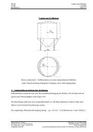
The foundation for a series <strong>of</strong> above ground <strong>cylindrical</strong> flat bottom tanks according to DIN 4119 has been<br />
prepared in a way that, under very special circumstances, formation <strong>of</strong> ice lenses could not be neglected.<br />
The stress-distribution in the shell wall due to a possible ice lens was investigated by FEM. It showed, that<br />
the tank wall is likely to buckle due to the size <strong>of</strong> the locally imposed deviations <strong>of</strong> the foot-ring.<br />
NOTATION<br />
f<br />
Circumferential coordinate <strong>of</strong> the tank. f = 0º denotes the meridian, under which the ice lens is acting<br />
Other symbols are explained in the relevant sections.<br />
SITUATION<br />
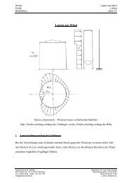
Somewhere in the new federal states <strong>of</strong> Germany a group <strong>of</strong> some fifteen flat bottom tanks according to DIN<br />
4119 had been built for the storage <strong>of</strong> petro-chemical products. The owner suspected, that the foundation <strong>of</strong><br />
the tanks had not been built according to the relevant technical rules <strong>and</strong> put the consultant <strong>of</strong>fice <strong>and</strong> the<br />
builder before court. The court asked Pr<strong>of</strong>. Mang for an expertise to answer questions such as<br />
- had the foundation <strong>of</strong> the tanks been planned <strong>and</strong> executed according to the relevant technical rules<br />
- is it possible, that ice lenses will form in the local situation<br />
- is it possible, that the tanks will be damaged by ice lenses<br />
- which technical measures could be taken to prevent damages by ice lenses<br />
It was obvious that the answers had to be given out <strong>of</strong> two different fields <strong>of</strong> engineering. Pr<strong>of</strong>essor Mang<br />
asked a colleague (third author in [5]) for co<strong>operation</strong>, who runs a consultants <strong>of</strong>fice in soil mechanics. The<br />
authors <strong>of</strong> the present paper prepared the answers for the tank shell under local load, which we will present<br />
in this paper.<br />
- 136 -
ANSWERS FROM SOIL MECHANICS<br />
The very complex interaction <strong>of</strong> particle size distribution, humidity <strong>and</strong> temperature cycles will not be<br />
discussed due to the length <strong>of</strong> the paper. We will just summarize the major features, which we used as<br />
boundary conditions when investigating the risk for the shells.<br />
- The present soil is likely to produce ice lenses<br />
- The possibility <strong>of</strong> critical frost conditions is not small<br />
(after 30 days with a 24-hour-mean-temperature <strong>of</strong> –10°C the soil is frozen up to a depth <strong>of</strong> 85 cm)<br />
- Single ice lenses can stack up to one meter height<br />
- Pressures from ice lenses can be<br />
15 kN/m 2 – 50 kN/m 2 in silt ('Schluff')<br />
50 kN/m 2 – 200 kN/m 2 in silty clay<br />
> 200 kN/m 2 in clay<br />
For the specific particle size distribution on site the ice can produce pressures <strong>of</strong> approx. 50 kN/m 2<br />
- The lift <strong>of</strong> the ice lenses can be in the order <strong>of</strong> "some cm"<br />
GEOMETRY OF THE TANK<br />
Radius<br />
17000 mm<br />
Height <strong>of</strong> eve<br />
16400 mm<br />
Footplate<br />
500 mm x 8 mm<br />
Bottom membrane (no value given, assumed 5 mm – 7 mm)<br />
Spherical ro<strong>of</strong><br />
Ro<strong>of</strong>-radius = 51000 mm, height <strong>of</strong> ro<strong>of</strong> top 19300 mm, plate thickness 5 mm, 42 rafters IPE 220<br />
Nominal volume: 15000m 3<br />
Approx. weight <strong>of</strong> <strong>steel</strong> structure (without foot <strong>and</strong> bottom membrane): 1860 kN<br />
Approx. snow load 680 kN<br />
TABLE 1. Strakes <strong>of</strong> the tank wall (overall effective wall thickness: 8.48 mm)<br />
No bottom top thickness <strong>steel</strong> grade s x,k (selfweight) s x,k<br />
[mm] [mm] [mm]<br />
[N/mm 2 ] [N/mm 2 ]<br />
1 0 2000 12.2 S 355 1.43 0.52<br />
2 2000 4500 9.6 S 355 < 1.81 0.66<br />
3 – 8 4500 16400 8 S355 / S 235 < 2.18 0.80<br />
(snow)<br />
(2 Ring stiffeners)<br />
Half wave lenth for the elastic chessboard pattern (strake no 1):<br />
L,el = 2pv(R*T) / vv[12*(1–µ 2 )] L,el = 1.57 m ( 4.1 )<br />
MODEL A<br />
The features <strong>of</strong> the problem were seen as:<br />
- thin walled <strong>cylindrical</strong> shell with meridional local edge load<br />
- the presence <strong>of</strong> the annular foot plate <strong>of</strong> the tank is beneficial for the distribution <strong>of</strong> the concentrated<br />
meridional compression stresses<br />
- It was decided, that FEM should not be used to evaluate the stability behaviour <strong>of</strong> the tank, but to give a<br />
rough approximation about the stress distribution in the tank wall.<br />
- the stability <strong>of</strong> the tank wall can be checked e.g. according to the suggestion <strong>of</strong> Knödel/Ummenh<strong>of</strong>er [3],<br />
[4]<br />
- 137 -
As a safe side assumption it was taken, that the compression forces <strong>of</strong> the ice lens go vertically upward<br />
towards the tank foot, without spreading to the sides. Further it was assumed, that if the ice lens would<br />
develop more than one meter along the circumference <strong>of</strong> the tank, a load <strong>of</strong> 50 kN could be transferred into<br />
the tank.<br />
Special attention was paid to the foundation <strong>of</strong> the tank.<br />
- Since the tank has a ro<strong>of</strong> structure (cladding plates on ro<strong>of</strong> trusses), strainless deformations <strong>of</strong> the shell will<br />
not be possible due to vertical deflections, which are locally imposed on the lower edge. The tank structure<br />
will be very stiff, it will show rigid body translations.<br />
- If the foundation is also very stiff the tank will - under a concentrated load - completely lift <strong>of</strong> the<br />
foundation until its lower edge will be doubly point loaded above the ice lens <strong>and</strong> at the opposite side.<br />
- For moderate stiffness <strong>of</strong> the foundation the tank will sink uniformly into the foundation due to its self<br />
weight (eventually with additional snow loads). A concentrated load from an ice lens will partially release<br />
this deformation.<br />
Following simplifications were made:<br />
- The stepped wall thickness <strong>of</strong> the tank was neglected, 12.2 mm were used throughout.<br />
- The ro<strong>of</strong> was modelled flat instead <strong>of</strong> spherical. In order to reduce the overestimated in-plane-stiffness the<br />
wall thicknes <strong>of</strong> the ro<strong>of</strong> was taken as one millimeter (instead <strong>of</strong> five).<br />
The properties <strong>of</strong> the different layers <strong>of</strong> the foundation were (from top to bottom)<br />
a) asphalt (neglected); b) broken stone layer, 0.30 m depth, 120 MN/m 2 ; c) natural soil, silty clay, 1.0 m<br />
effective depth, 45 MN/m 2<br />
The moduli given are for the secondary loading. The relation between primary <strong>and</strong> secondary loading was<br />
taken to be 2.4. The interaction between the ready built tank <strong>and</strong> the foundation is like a primary loading,<br />
therefore the above moduli have been divided by 2.4: b) 120 MN/m 2 / 2.4 = 50 MN/m 2 ; c) 45 MN/m 2 / 2.4<br />
= 19 MN/m 2 .<br />
Allowing for a foot with a width <strong>of</strong> 0.50 m, the resultant line-spring-stiffness for the foundation <strong>of</strong> the edge<br />
<strong>of</strong> the tank is c = 8.4 N/mm 2 (8.4 N/mm line-load to produce a deformation <strong>of</strong> 1 mm). The uniform<br />
settlement for the empty tank under dead load is<br />
uz = 18 N/mm / (8.4 N/mm 2 ) = 2.14 mm ( 5.1 )<br />
For the FE calculations ANSYS 5.3 was used (SHELL63). The mesh size was chosen to have<br />
circumferentional lengths <strong>of</strong> 2.5º or 740 mm from –10º = f = +10º <strong>and</strong> four times that size for the rest <strong>of</strong> the<br />
tank.<br />
Some data sets were calculated allowing for geometrical nonlinearities. No significant differences were<br />
found, compared to the linear calculations.<br />
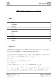
Under a load <strong>of</strong> 50 kN, which is applied to the bottom node at f = 0, the bottom edge <strong>of</strong> the tank lifts to 1,90<br />
mm at f = 0º <strong>and</strong> settles to 2.19 mm at f = 180º, which are differential settlements <strong>of</strong> –0.24 mm / +0,05<br />
mm. The maximum inward deflection <strong>of</strong> the wall above the local load is 0.6 mm. The distribution <strong>of</strong> the<br />
membrane-meridional stresses is given in fig 1. The maximum local compressive stress is 6.0 N/mm 2 .<br />
- 138 -
TABLE 2 Stability check for meridional membrane stresses according to DIN 18800 Teil 4<br />
4item eqn. formula present tank present tank<br />
strake no. 1 strake no. 2<br />
radius R [mm] 17000 17000<br />
wall thickness T [mm] 12.2 9.6<br />
length L [mm] 16400 16400<br />
Young's modulus E [N/mm 2 ] 2.1*10 5 2.1*10 5<br />
yield limit fy [N/mm 2 ] 360 360<br />
geometry parameter R/T 1393 1771<br />
geometry parameter L/R 0.965 0.965<br />
parameter (28) C x 1.00 1.00<br />
ideal critical stress (26) s xSi = 0.605 * C x * E * T/R 91.3 N/mm 2 71.8 N/mm 2<br />
normalised slenderness (1) ? Sx = v(fy/s xSi ) 1.99 2.24<br />
norm. real buckl. stress (8d)<br />
2<br />
? 2 = 0.2 / ? Sx 0.0507 0.040<br />
real buckling stress (4) s xS,R,k = ? 2 * fy 18.3 N/mm 2 14.4 N/mm 2<br />
partial safety factor (13) ? M 1.447 1.450<br />
buckling limit stress (9) s xS,R,d = s xS,R,k / ? M 12.6 N/mm 2 9.90 N/mm 2<br />
According to a suggestion <strong>of</strong> Knödel/Ummenh<strong>of</strong>er (1998) the buckling limit stress may be increased by a<br />
factor <strong>of</strong> 1.67, if local loads have been accounted for when evaluating the meridional membrane stress<br />
distribution. This is to compensate the effect, that the knock-down-factors in the buckling codes do already<br />
contain a part for uneven edge load distribution due to building tolerances. With this, the buckling limit<br />
stresses for the bottom strakes read as follows:<br />
strake no. 1: s xS,R,d = 1.67 * 12.6 N/mm 2 = 21.0 N/mm 2<br />
strake no. 2: s xS,R,d = 1.67 * 9.90 N/mm 2 = 16.5 N/mm 2<br />
Fig. 1 Distribution <strong>of</strong> meridional membrane stresses due to a 50 kN point load<br />
- 139 -
MODEL B<br />
In Model B we improved the tracing <strong>of</strong> the load situation. We modelled the tank's foot plate (SHELL181),<br />
the asphalt-layer, the broken stone layer <strong>and</strong> the silty-clay layer (SOLID45). The ice lens was modelled by<br />
imposing some lift to the bottom nodes <strong>of</strong> the lowest layer.<br />
TABLE 3 Properties <strong>of</strong> the soil layers<br />
layer depth [cm] modulus [MN/m 2 ]<br />
layer no item min max min median max<br />
0 tank foot – – – – –<br />
1 asphalt-concrete 8 8 10000<br />
2 frost resistant layer (broken stone) 40 55 30 50 80<br />
3 limed silty-clay 0 30 15 30 55<br />
4 untreated silty-clay, ICE LENS – – – – –<br />
The mesh for the <strong>steel</strong> structure was modified in a way, that we had much smaller elements at the<br />
concentrated load <strong>and</strong> a coarser mesh at the back <strong>of</strong> the tank. The smallest elements have a circumferential<br />
length <strong>of</strong> 0.5º or 150 mm with a height <strong>of</strong> 200 mm, the biggest elements have 15º or 4500 mm. The width <strong>of</strong><br />
the footplate elements as well as the elements <strong>of</strong> the soil layers beneath were chosen to be 83 mm (6<br />
elements on 500 mm).<br />
In order to keep element size rectangular <strong>and</strong> regular as wide as possible, we accepted some elements to<br />
have aspect ratios <strong>of</strong> 1:45. Since those are far <strong>of</strong>f the concentrated load, we assume that the results will not<br />
significantly be affected with respect to the desired accuracy.<br />
The soil pressure underneath the tank foot caused the edges <strong>of</strong> the foot plate to lift, which in turn produced<br />
tensile contact pressures between the surface <strong>of</strong> the top soil layer <strong>and</strong> the foot plate. In order to omit time<br />
consuming calculations with contact elements, we disconnected the outer nodes <strong>of</strong> the footplate. The<br />
footplate remains coupled to the top soil layer under the tank wall <strong>and</strong> at the next nodes at each side, which<br />
are situated in a distance <strong>of</strong> 83 mm each. This was considered to be sufficient to model the transfer <strong>of</strong> loads<br />
into the shell.<br />
The loads caused by the ice lens were modelled by imposing a displacement f to the nodes around the center<br />
<strong>of</strong> the ice lens, which is determined according to the function<br />
f = f0 * (1 – (r / (REL))**8) ( 6.1 )<br />
where<br />
f0 maximum lift in the center <strong>of</strong> the ice lens<br />
r distance <strong>of</strong> the respective node to the center <strong>of</strong> the ice lens<br />
REL radius <strong>of</strong> the ice lens<br />
The chosen shape <strong>of</strong> the ice lens' surface is arbitrary. It should be flat to account for plasticity <strong>of</strong> the ice lens<br />
<strong>and</strong> it should be zero along the edge <strong>of</strong> the ice lens to minimize peak shear deformations in the soil. The<br />
maximum lift f0 was chosen in a way, that the vertical pressures on the surface <strong>of</strong> the ice lens were close to<br />
50 kN/m 2 = 0.050 N/mm 2 .<br />
Following steps were taken to minimize vertical tensile stresses in the soil layers <strong>and</strong> as well to ab<strong>and</strong>on<br />
contact elements:<br />
- the soil layers were set under gravity load:<br />
- this generates compression forces in the soil, which compensate tensile forces from continuity<br />
- it was checked, which nodes near the ice lens have vertical tensile forces:<br />
- 140 -
- these were disconnected from the boundary conditions - in the subsequent calculations it was verified, that<br />
these nodes have upward deviations. Typically these nodes were covering a distance <strong>of</strong> 1.2*REL.<br />
We looked at two extreme configurations:<br />
- stiff foundation<br />
the soil layers have their minimum depths <strong>and</strong> their maximum moduli, the ice lens develops relatively<br />
close to the tank foot – this configuration is expected to give higher peak stresses in the tank<br />
- s<strong>of</strong>t foundation<br />
the soil layers have their maximum depths <strong>and</strong> their minium moduli, the ice lens develops relatively far<br />
from the tank foot – this configuration is expected to give lower peak stresses in the tank<br />
TABLE 3 Comparison <strong>of</strong> the results <strong>of</strong> Model B<br />
item stiff foundation s<strong>of</strong>t foundation<br />
uniform settlement under 18 N/mm [mm] 0.13 0.72<br />
max lift <strong>of</strong> ice lens [mm] 0.15 0.60<br />
differential settlement due to ice lens [mm] -0.014 / +0.00 –0.013 / 0.00<br />
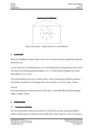
soil pressure above ice lens [kN/m 2 ] (see fig 2) 50 – 60 50<br />
soil pressure under tank foot [kN/m 2 ] 400 340<br />
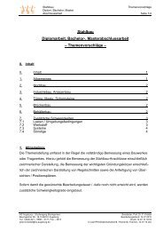
max meridional compression in tank [N/mm 2 ] (see fig 3) 2.4 1.9<br />
max inward deflection <strong>of</strong> the tank [mm] 0.2 0.1<br />
Fig. 2 Soil pressures – stiff foundation – maximum lift due to ice lens 0.15 mm<br />
- 141 -
Fig. 3 Meridional membrane stresses – stiff foundation – maximum lift due to ice lens 0.15 mm<br />
CONCLUSIONS<br />
- A local load <strong>of</strong> 50 kN caused by an ice lens seems to be much for a tank with R/T = 1400.<br />
- But this load corresponds to the self weight <strong>of</strong> the tank gathered along 2.8 m <strong>of</strong> circumference (or 9.4º)<br />
- The tank filled to a height <strong>of</strong> 15.4 m produces compressive stresses <strong>of</strong> approx. 150 kN/m 2 under it's<br />
bottom. This is by a factor <strong>of</strong> 3 higher than the pressures to be produced by an ice lens. The ice lens can<br />
develop under such conditions, but cannot produce any lift.<br />
- The critical state is when the tank is empty without snow load.<br />
- On the site under consideration ice lenses might develop, but they will not affect the stability <strong>of</strong> the tank.<br />
- Tanks founded on very fine clay may be critical.<br />
REFERENCES<br />
[1] DIN 4119: Oberirdische zylindrische Flachboden-Tankbauwerke aus metallischen Werkst<strong>of</strong>fen.<br />
Teil 1: Grundlagen, Ausführung, Prüfungen. Juni 1979.<br />
Teil 2: Berechnung. Februar 1980.<br />
[2] DIN 18800: Stahlbauten. Teil 4: Stabilitätsfälle, Schalenbeulen. November 1990.<br />
[3] Knödel, P., Ummenh<strong>of</strong>er, T. (1996): Stability <strong>of</strong> Axially Loaded Column Supported Shells. European<br />
Workshop Thin-Walled Steel Structures, September 26-28, 1996, Krzyzowa, Pol<strong>and</strong>.<br />
[4] Knödel, P., Ummenh<strong>of</strong>er, T. (1998): Ein einfaches Modell zum Stabilitätsnachweis zylindrischer<br />
Schalentragwerke auf Einzelstützen. Stahlbau 67 (1998), Heft 6, S. 425-429.<br />
[5] Mang, F., Knödel, P., Gottheil, K. (1999): Sachverständigengutachten, Teil 1 (expertise part I) –<br />
unpublished.<br />
- 142 -