Peterbilt Model 320 Operator's Manual after 8-07 - Peterbilt Motors ...
Peterbilt Model 320 Operator's Manual after 8-07 - Peterbilt Motors ...
Peterbilt Model 320 Operator's Manual after 8-07 - Peterbilt Motors ...

You also want an ePaper? Increase the reach of your titles
YUMPU automatically turns print PDFs into web optimized ePapers that Google loves.
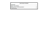
Heating And Air Conditioning Controls<br />
PART 4: CONTROLS AND DISPLAYS<br />
Heating System<br />
The heating system is a variable-coolant-flow type of system.<br />
• Hot engine coolant is circulated by the engine water<br />
pump through a heater core within the heater unit.<br />
• Two blowers force air through the core and into the<br />
cab.<br />
The amount of heat is controlled by:<br />
• the position of the modulating water valve that regulates<br />
hot engine coolant flow<br />
• the choice of fresh air or recirculated cab interior air as<br />
feed air to the blowers<br />
• the speed of the blowers<br />
The system’s controls are mounted in the header in front<br />
of the driver. They include the following (see illustration<br />
below):<br />
• A rotary knob to operate the modulating water valve<br />
(for air temperature control), located in the heater control<br />
head.<br />
• A rotary switch to select blower speed, located in the<br />
heater control head.<br />
02981A<br />
Next to the rotary knobs, two switches are available for the<br />
following functions:<br />
• A switch to select either fresh air or recirculated cab<br />
air as blower feed air.<br />
• A switch to select cab interior or defrost vents for<br />
heated air output.<br />
To heat the cab, select the "Cab” mode and the desired<br />
air source, then adjust the air temperature lever and blower<br />
speed until comfortable.<br />
– 38 – Y53-6015 R(08/<strong>07</strong>)