

U. Badstübner, J. Biela, J. W. Kolar, Power Density and Efficiency ...
U. Badstübner, J. Biela, J. W. Kolar, Power Density and Efficiency ...
U. Badstübner, J. Biela, J. W. Kolar, Power Density and Efficiency ...

Create successful ePaper yourself
Turn your PDF publications into a flip-book with our unique Google optimized e-Paper software.
lating the volume of the semiconductor heat sink including the<br />
fan based on the CSPI (Cooling System Performance Index)<br />
[17]:<br />
CSPI [ ]<br />
W<br />
1<br />
Kdm = [ 3<br />
R K<br />
] (1)<br />
th,S−a W V olCS [liter]<br />
with the thermal resistance R th,S−a of the heat sink <strong>and</strong> the<br />
volume of the heat sink including fan V ol CS .<br />
The volume <strong>and</strong> the shape of the transformer/inductor core<br />
<strong>and</strong> the two windings is determined in a second, inner optimization<br />
procedure, based on a transformer model as presented<br />
in [8], [15]. There, the volume of the transformer/inductor is<br />
minimized while keeping the temperatures below the allowed<br />
limits. The temperature distribution in the core/winding is<br />
calculated with a thermal model <strong>and</strong> the core <strong>and</strong> the winding<br />
losses (including HF-losses).<br />
The resulting minimized transformer/inductor volume are<br />
passed to the global optimization algorithm together with the<br />
volumes of the heat sink <strong>and</strong> capacitors. Based on the result<br />
the free parameter values are systematically varied until a<br />
minimal system volume <strong>and</strong>/or maximal efficiency is obtained.<br />
More detailed information about the optimization <strong>and</strong> the<br />
corresponding models can be found in [1], [8], [12], [15]<br />
IV. OPTIMIZATION AND SIMULATION RESULTS<br />
Based on the optimization procedure presented in the preceding<br />
section the three considered topologies – phase shift<br />
with capacitive output filter <strong>and</strong> current doubler as well as the<br />
resonant converter with capacitive output filter – have been<br />
optimized for the data given in table I <strong>and</strong> II. The resulting<br />
operating parameters are presented in table III.<br />
The highest power density is achieved with the seriesparallel<br />
resonant converter: 19.1 kW/ltr. (313 W/in 3 ) if only<br />
the net component volumes, the PCBs <strong>and</strong> housings are<br />
considered. The final system volume strongly depends on<br />
the 3D design of the converter. For the prototype shown in<br />
Fig. 1 the power density resulting of the optimization was<br />
15 kW/ltr., which is lower than the results presented here since<br />
other components have been used during the optimization of<br />
this converter. The final assembled converter had 10 kW/ltr.<br />
(164 W/in 3 ), what results in a scaling factor of 2/3 between<br />
calculated <strong>and</strong> final power density.<br />
The phase-shift converters achieve a power densities of<br />
14.7 kW/ltr. (with current doubler) <strong>and</strong> 11.7 kW/ltr. (with<br />
capacitive output filter). If the scaling factor is assumed as<br />
for the assembled resonant prototype, the total system power<br />
density of the presented resonant converter is 12.7 kW/ltr.<br />
(208 W/in 3 ), for the phase-shift converter with current doubler<br />
7.8 kW/ltr.(128 W/in 3 ) <strong>and</strong> with capacitive output filter<br />
10 kW/ltr. (164 W/in 3 ).<br />
At the operation point, optimized for maximum power<br />
density, the efficiency of the resonant converter is 96.2 %, for<br />
the phase shift converter with current doubler 94.8 % <strong>and</strong> with<br />
capacitive output 95.0 % respectively. However, an optimum<br />
efficiency results in different switching frequencies for all<br />
three converters, as shown in Fig. 4. For the resonant converter<br />
the efficiency increases to 96.3 % with an increased switching<br />
frequency (≈220 kHz), because there, the losses of the<br />
transformer are lower. The phase-shift converter achieves the<br />
maximum efficiency when operating with ≈100 kHz mainly<br />
driven by the decreasing losses of the semiconductors which<br />
drastically increase above 300 kHz. A similar behavior shows<br />
the phase shift converter with the capacitive output filter.<br />
There, the losses becomes minimum at the lowest considered<br />
frequency of 25 kHz. However, with the increasing efficiency<br />
of the phase shift converter at lower switching frequencies the<br />
volume of the magnetic components(transformer <strong>and</strong> inductor)<br />
increases significantly, which results in much smaller power<br />
density as shown in Fig. 4.<br />
The dimensions of the ferrite cores (EPCOS N87) are also<br />
included in table III <strong>and</strong> illustrated in Fig. 5. In the optimization<br />
of the magnetic devices <strong>and</strong> foil windings, where only<br />
one turn per layer is realized, have been assumed. Moreover,<br />
the integration of the required series/leakage inductance for<br />
the three converters in the transformer is considered in the<br />
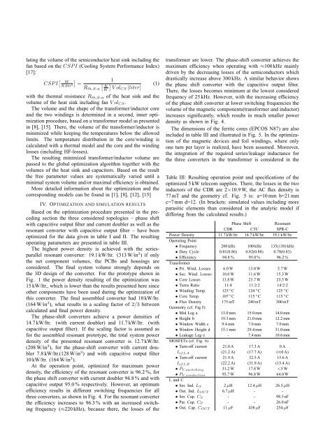
Table III: Resulting operation point <strong>and</strong> specifications of the<br />
optimized 5 kW telecom supplies. There, the losses in the two<br />
inductors of the CDR are 2×10.9 W, the AC flux density is<br />
77 mT <strong>and</strong> the geometry cf. Fig. 5 is: a=10 mm b=21 mm<br />
c=7 mm d=12. (In brackets: simulated values including more<br />
parasitic elements than considered in the analytic model if<br />
differing from the calculated results.)<br />
Phase Shift<br />
Resonant<br />
CDR CTC SPR-C<br />
<strong>Power</strong> <strong>Density</strong> 11.7 kW/ltr. 14.7 kW/ltr. 19.1 kW/ltr.<br />
Operating Point<br />
• Frequency 200 kHz 100 kHz 135(130) kHz<br />
• Duty Cycle 0.81(0.86) 0.82(0.88) 0.78(0.83)<br />
• <strong>Efficiency</strong> 94.8 % 95.0 % 96.2 %<br />
Transformer<br />
• Pri. Wind. Losses 6.0 W 13.0 W 5.7 W<br />
• Sec. Wind. Losses 10.0 W 11.6 W 15.3 W<br />
• Core Losses 13.8 W 23.7 W 23.5 W<br />
• Turns Ratio 11:4 11:2:2 14:2:2<br />
• Winding Temp. 125 ◦ C 124 ◦ C 125 ◦ C<br />
• Core Temp. 107 ◦ C 115 ◦ C 115 ◦ C<br />
• Flux <strong>Density</strong> 175 mT 240 mT 300 mT<br />
Geometry (cf. Fig.5)<br />
• Mid Leg a 13.0 mm 15.0 mm 14.0 mm<br />
• Height b 19.3 mm 21.0 mm 12.2 mm<br />
• Window Width c 9.4 mm 7.0 mm 7.0 mm<br />
• Window Height d 15.1 mm 29.4 mm 31.0 mm<br />
• Leakage Leg e - 7.4 mm 10.6 mm<br />
MOSFETs (cf. Fig. 6)<br />
• Turn-off current 21.0 A 17.3 A 0 A<br />
I off,A (21.2 A) (17.7 A) (≈0 A)<br />
• Turn-off current 21.9 A 32.5 A 15.6 A<br />
I off,B (22.2 A) (31.9 A) (15.4 A)<br />
• P V,switching 31.2 W 17.8 W


