Manual for Radiance R200i - Perreaux Industries
Manual for Radiance R200i - Perreaux Industries
Manual for Radiance R200i - Perreaux Industries

You also want an ePaper? Increase the reach of your titles
YUMPU automatically turns print PDFs into web optimized ePapers that Google loves.
<strong>Perreaux</strong> <strong>Industries</strong> Limited makes no warranty <strong>for</strong> the use of its products, other than those<br />
expressly contained in the warranty detailed herein. The Company assumes no responsibility<br />
<strong>for</strong> any errors which may appear in this document, reserves the right to change products or<br />
specifications detailed herein at any time without notice, and does not make any commitment<br />
to update the in<strong>for</strong>mation contained herein. No licenses to patents or other intellectual<br />
property of <strong>Perreaux</strong> are granted by the Company in connection with the sale of <strong>Perreaux</strong><br />
products, expressly or by implication.<br />
<strong>Perreaux</strong> is a registered trademark of <strong>Perreaux</strong> <strong>Industries</strong> Ltd.<br />
Terms and product names in this document may be trademarks of others.<br />
2
i<br />
The Decision Making Process<br />
In this section, our objective is to help you extract the most out of your<br />
investment in your audio system. May we take a moment of your time<br />
with the following suggestions.<br />
The aim of high fidelity audio is to attempt to recreate the original<br />
per<strong>for</strong>mance in its entirety via the recorded medium. To help you get to<br />
know what various instruments really do sound like, listen to live concerts<br />
of musical per<strong>for</strong>mances that you prefer. Select a few recordings of similar<br />
per<strong>for</strong>mances <strong>for</strong> comparison. Your <strong>Perreaux</strong> equipment will (and the rest<br />
of your system should) provide a precise duplication in your listening area<br />
of the total musical per<strong>for</strong>mance, including the ambience of the venue in<br />
which the recording was made.<br />
Read<br />
Magazines<br />
Choose Your<br />
Hi-Fi Dealer<br />
Carefully<br />
Read hi-fi and audiovisual magazines, particularly the equipment reviews<br />
and letters to the editor sections. Use these as a general guide only, and try<br />
to read "between the lines". Remember no one specifically sets out to<br />
downgrade a particular piece of equipment, so what is not included in the<br />
review is often as important as the actual printed content.<br />
Choose your hi-fi dealer carefully; they are your professional guide.<br />
Preferably, they should be knowledgeable about music and recording<br />
techniques as well as the equipment itself. They should be able to provide<br />
a total service, including installation, system "tuning" advice, problem<br />
solving and after sales service. Frequent your dealer and listen to a variety<br />
of equipment using recordings, which are familiar to you. Ask questions<br />
and listen to advice, but remember to trust your own ears to tell you what<br />
sounds right <strong>for</strong> you. If possible, listen to your equipment choice in your<br />
own listening area be<strong>for</strong>e you finally make your purchase.<br />
When deciding on your system you will need to differentiate between sales<br />
gimmicks and cosmetic wizardry, as against practical features and<br />
facilities. Recognise the "Christmas Tree Syndrome"- namely, the more<br />
flashing lights and switches the better it must be. Bear in mind that you are<br />
paying <strong>for</strong> these, and because of the necessity of careful pricing,<br />
compromises may have been made in the internal component quality vital<br />
<strong>for</strong> accurate sound reproduction. Each component through which the audio<br />
signal must pass will add its own character to the music you hear, hence<br />
the expression, "colouration". <strong>Perreaux</strong> products are carefully designed to<br />
minimise componentry within the audio signal path. All componentry used<br />
is of highest quality and only included when absolute necessity is<br />
established; no component is there <strong>for</strong> a free ride or to correct <strong>for</strong><br />
deficiencies elsewhere in the circuitry. With <strong>Perreaux</strong>, emphasis is placed<br />
on maximum sound quality, component and unit reliability and long life.<br />
3
ii<br />
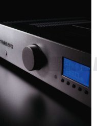
Introducing the<br />
<strong>Perreaux</strong> <strong>Radiance</strong> Series<br />
The <strong>Perreaux</strong> “<strong>Radiance</strong>” series is our finest quality offering. This series<br />
incorporates some of the highest levels of audio engineering available<br />
today.<br />
Key Features<br />
Compact<br />
Stylish<br />
High-powered design<br />
Dual mono, linear power supply construction<br />
Enhanced audio design – featuring, non-invasive protection system,<br />
full DC coupling, minimal internal wiring, non-magnetic<br />
componentry and advanced MOSFET output stage<br />
Fully microprocessor controlled – featuring, high-level control,<br />
protection and display options<br />
Remote controller, custom designed and built<br />
Phono and USB options<br />
Fully software upgradeable<br />
The <strong>Perreaux</strong> “<strong>Radiance</strong>” series takes you even closer to the elusive<br />
goal of “The Perfect Re-creation of a Musical Event”.<br />
From all of us at <strong>Perreaux</strong> <strong>Industries</strong> Limited, thank you <strong>for</strong> choosing the<br />
<strong>Perreaux</strong> <strong>Radiance</strong> Series <strong>R200i</strong> integrated amplifier.<br />
Martin van Rooyen<br />
Managing Director<br />
<strong>Perreaux</strong> <strong>Industries</strong> Ltd<br />
4
iii<br />
Important Safety Instructions<br />
Note:<br />
Please read all instructions carefully be<strong>for</strong>e attempting to operate<br />
your <strong>Perreaux</strong> <strong>R200i</strong> integrated amplifier.<br />
Please disconnect your system from the mains be<strong>for</strong>e attempting to<br />
connect or disconnect cables.<br />
Please disconnect your system from the mains be<strong>for</strong>e attempting to<br />
clean your unit.<br />
Please keep electrical equipment out of reach of children.<br />
Please unplug sensitive electronic equipment during electrical<br />
storms.<br />
Please replace any fuse with the value and type specified.<br />
DO NOT disconnect the mains earth from the system.<br />
Avoid operating the <strong>R200i</strong> with the cover removed.<br />
Avoid using any liquid inside the <strong>R200i</strong>.<br />
Avoid restricting or blocking ventilation access <strong>for</strong> the <strong>R200i</strong>.<br />
DO NOT bypass any fuse.<br />
DO NOT attempt to repair the <strong>R200i</strong>. In the event of a problem,<br />
please contact your <strong>Perreaux</strong> dealer.<br />
Avoid exposing the <strong>R200i</strong> to extremely high or low temperatures.<br />
DO NOT operate this product in an explosive atmosphere.<br />
5
iv<br />
Table of Contents<br />
i The Decision Making Process........................................................................... 3<br />
Read Magazines .................................................................................................................3<br />
Choose Your Hi-Fi Dealer Carefully ..............................................................................3<br />
ii Introducing the <strong>Perreaux</strong> <strong>Radiance</strong> Series.................................................... 4<br />
Key Features........................................................................................................................4<br />
iii Important Safety Instructions .......................................................................... 5<br />
iii<br />
iv Table of Contents............................................................................................... 6<br />
1 Features at a Glance.......................................................................................... 9<br />
Remote Controller .............................................................................................................9<br />
Integrated Amplifier..........................................................................................................9<br />
Optional Modules........................................................................................................... 12<br />
2 Special Design Features..................................................................................13<br />
An Integrated Amplifier?.............................................................................................. 13<br />
Emphasis on Size............................................................................................................. 13<br />
Construction..................................................................................................................... 13<br />
The User Interface .......................................................................................................... 14<br />
Minimalist Design ........................................................................................................... 14<br />
The Power Supplies........................................................................................................ 15<br />
The Preamplifier Section ............................................................................................... 16<br />
The Volume Control....................................................................................................... 17<br />
The Output Stage ........................................................................................................... 17<br />
Protection Functions...................................................................................................... 17<br />
Input Configuration ....................................................................................................... 17<br />
The Role of the Micro-Processor................................................................................. 17<br />
3 Protection Functions .......................................................................................18<br />
External AC Supply Protection.................................................................................... 18<br />
Maximum Volume Protection ..................................................................................... 19<br />
Internal AC Supply Protection..................................................................................... 19<br />
Clipping Protection ........................................................................................................ 19<br />
Over Current Protection ............................................................................................... 20<br />
Over Temperature Protection ..................................................................................... 20<br />
DC Offset Protection...................................................................................................... 21<br />
Internal Fuse Failure Protection.................................................................................. 21<br />
Multiple Faults ................................................................................................................. 21<br />
4 Unpacking and Placement .............................................................................22<br />
Unpacking Procedure ................................................................................................... 22<br />
Box Contents.................................................................................................................... 23<br />
Placing Your <strong>R200i</strong> ......................................................................................................... 23<br />
Ventilation Requirements............................................................................................. 23<br />
6
5 Rear Panel Functions.......................................................................................24<br />
6 Front Panel Interaction...................................................................................30<br />
Buttons .............................................................................................................................. 30<br />
Vacuum Fluorescent Display....................................................................................... 31<br />
7 Instant Install ....................................................................................................32<br />
8 Using the Remote Controller .........................................................................34<br />
Installation of Batteries.................................................................................................. 34<br />
Operating the Remote Controller.............................................................................. 35<br />
9 Interacting with Your <strong>R200i</strong>...........................................................................37<br />
Default Screen ................................................................................................................. 37<br />
Menu Screen .................................................................................................................... 37<br />
Menu Overview............................................................................................................... 38<br />
Input Select....................................................................................................................... 39<br />
Preamp Setup................................................................................................................... 40<br />
Balance Control................................................................................................................................40<br />
Maximum Volume ..........................................................................................................................40<br />
Initial Volume.....................................................................................................................................41<br />
Bypass Preamp..................................................................................................................................41<br />
Display Setup ................................................................................................................... 42<br />
Brightness ............................................................................................................................................42<br />
Display Timeout................................................................................................................................43<br />
System Setup.................................................................................................................... 43<br />
Speaker B .............................................................................................................................................43<br />
Energy Saver ......................................................................................................................................44<br />
Input Labels ........................................................................................................................................45<br />
Factory Reset......................................................................................................................................46<br />
Factory Reset Settings....................................................................................................................47<br />
Diagnostics ....................................................................................................................... 47<br />
Unit Info................................................................................................................................................47<br />
Heat Sink Temp.................................................................................................................................48<br />
10 Upgrading Your <strong>R200i</strong> ....................................................................................49<br />
Optional Modules........................................................................................................... 49<br />
11 Maximising System Potential .........................................................................50<br />
Interconnects and Speaker Cables ............................................................................ 50<br />
Bi-amping.......................................................................................................................... 50<br />
Balanced Interconnects ................................................................................................ 51<br />
Positioning Ancillary Equipment................................................................................ 51<br />
Loudspeaker Placement................................................................................................ 51<br />
Matching Amplifier and Speaker Ratings................................................................. 52<br />
Final Thoughts................................................................................................................. 52<br />
12 The Power MOSFET .........................................................................................53<br />
12<br />
The MOSFET..................................................................................................................... 53<br />
Other Field Effect Devices............................................................................................ 53<br />
Audio Applications......................................................................................................... 54<br />
Secondary Breakdown.................................................................................................. 54<br />
7
High Frequency Response........................................................................................... 55<br />
Other Advantages.......................................................................................................... 55<br />
13 Frequently Asked Questions .........................................................................56<br />
13<br />
14<br />
14 Care and Maintenance....................................................................................59<br />
Cover .................................................................................................................................. 59<br />
Front Panel and Remote Controller........................................................................... 59<br />
15 Faultfinding Your <strong>R200i</strong>..................................................................................60<br />
15<br />
Cause and Elimination of Hum................................................................................... 60<br />
Identifying and Isolating Problems............................................................................ 61<br />
Faultfinding Flowchart.................................................................................................. 64<br />
Description of Amplifier Faults.................................................................................... 65<br />
16 Warranty In<strong>for</strong>mation and Obtaining Service............................................66<br />
16<br />
1 Year Limited Warranty............................................................................................... 66<br />
5 Year Extended Warranty........................................................................................... 66<br />
Warranty Transfer........................................................................................................... 66<br />
In<strong>for</strong>mation on the <strong>Perreaux</strong> <strong>R200i</strong> Warranty........................................................ 66<br />
17 Extended Warranty Registration Form........................................................68<br />
17<br />
18<br />
18 Specifications ....................................................................................................69<br />
Specifications in Brief..................................................................................................... 69<br />
Preamplifier Specifications Explained........................................................................ 71<br />
Power Amplifier Specifications Explained................................................................ 63<br />
19 Physical Dimensions ........................................................................................76<br />
19<br />
20<br />
20 Contact Details .................................................................................................77<br />
8
1 Features at a Glance<br />
Remote<br />
Controller<br />
Fully Featured<br />
Full control of the amplifier, and connected <strong>Perreaux</strong> <strong>Radiance</strong> series<br />
peripherals is possible with the custom designed 36-button remote<br />
controller.<br />
LED Indication<br />
Each time a key is depressed, a LED representing the selected source is<br />
illuminated briefly. This greatly avoids confusion.<br />
Compact and Ergonomic<br />
Designed to sit snugly in the palm of your hand, the remote is compact,<br />
com<strong>for</strong>table to hold and practical to use.<br />
Quality<br />
The remote is constructed from high quality cast zinc and acrylic materials.<br />
Custom Designed and Built<br />
The remote has been custom designed and built by the <strong>Perreaux</strong> engineers<br />
and befits the <strong>Radiance</strong> series perfectly.<br />
Integrated<br />
Amplifier<br />
Integrated<br />
By eliminating the interface between separate pre and power amplifiers and<br />
removing concerns about impedance matching, the <strong>R200i</strong> provides a<br />
shorter, purer signal path without costly exposed interconnect cables and<br />
separate power cords.<br />
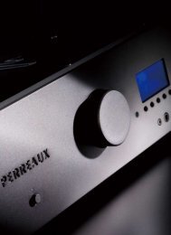
Stylish<br />
The front panel is carved from 10mm (0.39 inch) thick aluminium, and<br />
then heavily electroplated in either a Satin or Black Chrome finish.<br />
Particular attention has been paid to every aspect of the product styling.<br />
All control functions and display settings are accessed from within the<br />
central ellipse on the front panel. The cover is made from high gloss black<br />
acrylic.<br />
Compact<br />
At 430mm wide x 105mm high x 340mm deep (16.9” x 4.1” x 13.4”) The<br />
<strong>R200i</strong> is extremely compact.<br />
Highly Powered<br />
Capable of continuously delivering 200W into 8Ω (360W into 4Ω), the<br />
<strong>R200i</strong> is highly powered. Utilising 6 very high current Toshiba MOSFETs<br />
per channel, the <strong>R200i</strong> handles even the most difficult loads with ease.<br />
9
Dual Mono Construction<br />
Featuring dual mono construction. There are two separate toroidally<br />
wound power supplies, rectification and smoothing sections. This<br />
topology maintains maximum channel separation independent of load.<br />
Dual Capacitive Smoothing<br />
Four filter capacitors (40,000uF per channel, 80,000uF total) per channel<br />
are coupled in parallel to reduce power supply resistance. The power<br />
supply is extremely rigid, capable of delivering huge amounts of power<br />
instantaneously. The result is significantly improved dynamic capabilities.<br />
Separate Control Toroidal Power Supply<br />
All control circuitry is supplied from a separate toroidally wound multi tap<br />
trans<strong>for</strong>mer. This eliminates any risk of noise contamination through the<br />
supply.<br />
Large High Quality Binding Posts/Speaker B Selector<br />
The output of the amplifier features two pairs of high quality binding posts<br />
per channel that enables two separate zones to be controlled. Alternately at<br />
the touch of a button they can be internally coupled, and used <strong>for</strong> bi wiring<br />
a single pair of speakers.<br />
Sophisticated Protection Package<br />
The <strong>R200i</strong> features a sophisticated protection package <strong>for</strong> the amplifier and<br />
connected load. Protection covering: supply (soft charge), clipping, over<br />
current, over temperature, DC offset, internal AC supply, DC fuse<br />
protection.<br />
Non-Invasive Protection<br />
The protection is non-invasive and there<strong>for</strong>e will not alter or degrade the<br />
signal path<br />
Full DC Coupling<br />
The amplifier is fully DC coupled from the preamplifier input terminals to<br />
the speaker binding posts.<br />
Totally Microprocessor Controlled<br />
All functions are managed by a powerful onboard microprocessor.<br />
Full In<strong>for</strong>mation<br />
In the event that the amplifier protects itself, the user is fully in<strong>for</strong>med of<br />
any activity via the display.<br />
Highest-Grade Double-Sided Printed Circuit Boards<br />
All printed circuit boards utilised within the <strong>R200i</strong> are constructed from the<br />
highest-grade fiberglass base stock. Tracks are etched from 2oz copper.<br />
This provides added stability under variable thermal or electrical loads and<br />
assures maximum signal integrity, separation and product life.<br />
10
Minimal Internal Wiring<br />
Meticulous attention to the overall design and placement of each<br />
component has resulted in an internal environment that is virtually devoid<br />
of all internal wiring.<br />
Ultra Short Signal Path<br />
Careful attention has been paid to the signal path within the amplifier. It is<br />
ultra short and very carefully routed to avoid power components and digital<br />
lines.<br />
Thermal Management System<br />
Comprehensive thermal monitoring. Left and right heat sink temperature<br />
(Cº) is displayed in real time on the display. These variables are utilised by<br />
the microprocessor <strong>for</strong> individual channel over temperature monitoring and<br />
protection.<br />
Non-Magnetic Components Used <strong>for</strong> the Chassis and Cover<br />
The chassis and all associated metalwork have been manufactured from<br />
high quality grade aluminum and acrylic. These high quality non-magnetic<br />
components negate the possibility of harmful circulating eddy currents<br />
building up within the amplifier.<br />
Directly Soldered Preamplifier Inputs and Outputs<br />
Preamplifier Inputs and Outputs are directly soldered to the printed circuit<br />
board. There are no connecting cables to increase parasitic inductance,<br />
capacitance and resistance.<br />
Highly Customisable<br />
The <strong>R200i</strong> is highly user configurable. Options to assign input labels,<br />
balance, initial volume, maximum volume, brightness, display timeout,<br />
energy saver, speaker B and last input used, provide maximum flexibility<br />
to the user. All user settings are retained in non-volatile EEPROM.<br />
Home Theatre Integration<br />
The preamplifier bypass function enables ef<strong>for</strong>tless integration into a home<br />
theatre system.<br />
Two-Volume Level Instruction Set<br />
The <strong>R200i</strong> can be programmed with two volume level instruction sets. The<br />
first set applies a default to the switch on volume level. The second applies<br />
a limit to the maximum setting of the volume control.<br />
Dual Ramp Speed Volume Control<br />
The volume control ramps upward from 0 to 59 in approximately 10<br />
seconds and downward from 59 to 0 in approximately 5 seconds.<br />
11
Smart Mute<br />
The muting function integrates seamlessly with the volume control. Under<br />
normal conditions, depressing mute will completely attenuate the volume<br />
control. While in mute mode the user can reduce the volume level<br />
(volume –), so that when volume is restored it will recommence at the<br />
reduced setting. This action will not alter the mute function. Conversely if<br />
the volume level is increased (volume +), this instantaneously overrides<br />
any mute action and increases the volume setting from it’s pre-mute state.<br />
Large Format Alphanumeric Vacuum Fluorescent Display<br />
The <strong>R200i</strong> display is a sharp and bright alphanumeric vacuum fluorescent<br />
display (VFD) featuring a 2-line/16-character display. The software has<br />
been utilised to provide double-height digits, a bar graph of volume, the<br />
input currently selected and other settings and options.<br />
Adjustable Display Lighting<br />
The display of the <strong>R200i</strong> can be adjusted to suit ambient room conditions,<br />
4 adjustable settings are available. Alternately the display lighting can be<br />
switched off.<br />
Remote On/Off<br />
The <strong>R200i</strong> and connected peripherals can be remotely switched on and off.<br />
Energy Saver Feature<br />
There are 8 internal timers available that enable the amplifier to run <strong>for</strong> a<br />
period of time then power down into standby mode. These range from 1<br />
hour through to 2 days.<br />
Future-Proof<br />
Your distributor is capable of upgrading the software contained on both<br />
amplifier and remote handset via a connected PC. This protects and futureproofs<br />
your investment in the <strong>Perreaux</strong> <strong>R200i</strong>.<br />
Optional<br />
Modules<br />
Moving Coil/Magnet Phono Stage<br />
The <strong>R200i</strong> features a very high quality phono stage option.<br />
USB Connection<br />
This option facilitates the streaming of music directly from your<br />
computer’s hard disc drive. Incorporating a very high-resolution digital to<br />
analog converter (DAC) module, this option is designed to further enhance<br />
your flexibility and enjoyment with the <strong>R200i</strong>.<br />
12
2 Special Design Features<br />
An<br />
Integrated<br />
Amplifier?<br />
<strong>Perreaux</strong> has been designing and manufacturing only the highest quality<br />
audio componentry <strong>for</strong> more than a quarter of a century. Technology has<br />
continued to evolve rapidly over that time and our knowledge and<br />
application of design, materials and manufacturing techniques has<br />
advanced in tandem with this. Today’s <strong>Perreaux</strong> range comes closer to<br />
fulfilling our company’s shared vision than at any other time in the past.<br />
The <strong>R200i</strong> has been developed to meet customer demands <strong>for</strong> compact<br />
higher quality products. Careful attention has been taken throughout the<br />
development phase, not to make compromises that would degrade the high<br />
quality of reproduction that the unit is capable of delivering.<br />
To follow is a discussion on some of the technological design features that<br />
have been incorporated into the <strong>R200i</strong>.<br />
Emphasis on<br />
Size<br />
Construction<br />
At 430mm wide x 105mm high x 340mm deep (16.9” x 4.1” x 13.4”) it’s<br />
low profile and small footprint ensure that the <strong>R200i</strong> can be used in almost<br />
any environment.<br />
The milled aluminium front panel, thick black acrylic cover, functional<br />
heat sinks and solid remote controller are all hallmarks of the <strong>Perreaux</strong><br />
brand.<br />
The beautifully styled front panel is milled from solid 10mm (0.39 inch)<br />
thick aluminium and offered in either Satin or Black Chrome electroplate<br />
finishes. Inset within the elongated ellipse is a blue alphanumeric vacuum<br />
fluorescent display, all functions are accessed via 5 individually backlit<br />
push buttons.<br />
The cover is manufactured from thick black acrylic. No cover fixing<br />
screws are visible. A series of slots run down each side of the cover to<br />
facilitate air ventilation.<br />
By placing the heat sinks on the outside of the product, the <strong>R200i</strong>, they are<br />
able to breathe freely and operate at highest efficiency.<br />
The multifunction remote controller is small, stylish and ergonomically<br />
designed <strong>for</strong> com<strong>for</strong>t. It is manufactured from cast zinc alloy and offered<br />
in either Satin or Black Chrome electroplate finishes, matching the <strong>R200i</strong><br />
front panel.<br />
13
The User<br />
Interface<br />
The user interface is a blend of minimalism, functionality and aesthetics.<br />
Front Panel Interface.<br />
All user interaction takes place within the ellipse. The highest level of user<br />
interaction is assured via the 2-line/16-character alphanumeric vacuum<br />
fluorescent display (VFD). In combination with the VFD, the five large<br />
<strong>for</strong>mat buttons with backlit labels situated either side of the display,<br />
provide the user with full interaction.<br />
Handheld Remote Controller<br />
The 36 button remote controller has been designed to provide complete<br />
interaction with the <strong>R200i</strong> and other nominated <strong>Perreaux</strong> peripherals.<br />
On account of the compactness of design, all functions are accessible with<br />
your thumb.<br />
Minimalist<br />
Design<br />
Leading British architect, John Pawson, writes:<br />
“The Minimum can be defined as the perfection that an object<br />
achieves when it is no longer possible to improve it by<br />
subtraction. This is the quality that an object has when every<br />
component, every detail, and every junction has been reduced<br />
or condensed to the essentials. It is the result of the omission<br />
of the inessentials”.<br />
<strong>Perreaux</strong> has historically embraced the minimalist ethic from an audio<br />
design perspective only. The concept of “less equating to more” has been<br />
at the heart of all <strong>Perreaux</strong> audio designs <strong>for</strong> more than a quarter of a<br />
century.<br />
Minimalist Electronics<br />
We wish to maximise the quality of your listening pleasure by keeping the<br />
componentry and signal path as uncluttered, short and clean possible. All<br />
components in the signal path, even those of the highest quality have an<br />
effect on the signal, thereby altering the quality of the reproduction in some<br />
way. Our aim is to recreate in its entirety, the original per<strong>for</strong>mance by not<br />
adding or subtracting anything, irrespective of the source.<br />
Minimalist User Interface<br />
We carefully study the user interface and par down the number of buttons<br />
and associated clutter leaving just the essential and no more. How tempting<br />
it has been over the years to loose sight of our core values as technology or<br />
trends have made it possible. That is one of the reasons why our older<br />
products still have such a high resale value today. The user interface has and<br />
always will remain simple, free from adornments, clean and uncluttered.<br />
14
Minimalist Aesthetics<br />
Our products appeal to those who seek the ultimate in audio exclusivity,<br />
namely the perfect blend of “<strong>for</strong>m and function”.<br />
“Form and function” are both tough masters. That is why our amplifier<br />
heat sinks are not hidden, but instead feature prominently in all our<br />
designs. We make no excuses <strong>for</strong> producing some of the most distinctive<br />
high-end audio products on the planet. We let “<strong>for</strong>m and function” blend<br />
together in perfect harmony. This surely is the essence of true minimalist<br />
utilisation.<br />
Minimalism in a Wider Context<br />
John Pawson writes:<br />
“Clearly simplicity has dimensions to it that go beyond the<br />
purely aesthetic: it can be seen as the reflection of some innate,<br />
inner quality, or the pursuit of philosophical or literary insight<br />
into the nature of harmony, reason, and truth”.<br />
The Power<br />
Supplies<br />
The <strong>Perreaux</strong> <strong>R200i</strong> features four separate power supplies, whose task it is<br />
to provide clean, stable DC power to the various circuit elements within the<br />
amplifier.<br />
Toroid<br />
Trans<strong>for</strong>mer<br />
Rectification<br />
Stage<br />
Smoothing<br />
Section<br />
To Left PA<br />
AC Sense<br />
AC<br />
Soft Start<br />
Toroid<br />
Trans<strong>for</strong>mer<br />
AC Sense<br />
Rectification<br />
Stage<br />
Smoothing<br />
Section<br />
To Right PA<br />
Toroid<br />
Trans<strong>for</strong>mer<br />
Rectification<br />
Stage<br />
Smoothing<br />
Section<br />
Regulation<br />
Pre<br />
Amplification<br />
Choke<br />
Toroid<br />
Trans<strong>for</strong>mer<br />
Rectification<br />
Stage<br />
Smoothing<br />
Section<br />
Regulation<br />
Digital<br />
Control Toroid<br />
Regulation<br />
Display<br />
15
Control Voltage Supply<br />
All user interface digital and control circuits, source their power from an<br />
isolated DC supply. The supply features a custom wound, multi tap<br />
toroidal trans<strong>for</strong>mer directly soldered to the PCB. By incorporating a<br />
separate control supply, it minimises the possibility of noise entering the<br />
audio circuitry.<br />
Preamplifier Voltage Supply<br />
The preamplifier section is also powered from it’s own separate low<br />
voltage supply, thereby further reducing the possibility of noise entering<br />
the audio circuitry.<br />
Separate Left and Right Channel Power Supplies (Dual-Mono)<br />
The concept behind dual-mono topology is to incorporate two amplifiers<br />
within a single enclosure. By incorporating 2 x high quality power<br />
supplies into the design, the <strong>R200i</strong> maintains maximum channel separation.<br />
Huge Smoothing Section<br />
Four filter capacitors (40,000uF per channel, 80,000uF total) per channel<br />
are coupled in parallel <strong>for</strong> greatly reduced power supply resistance and,<br />
consequently, significantly improved dynamic capabilities.<br />
The sonic benefits of a power supply as high a quality as the <strong>R200i</strong> has are<br />
significant, resulting in ef<strong>for</strong>tless reproduction of dynamic contrast as well<br />
as stable and detailed stereo imaging.<br />
The<br />
Preamplifier<br />
Section<br />
The preamplifier features five analogue input pairs. Four pairs of single<br />
ended RCA inputs and a single pair of balanced XLR inputs.<br />
A high quality, class A phono stage can be installed within the <strong>R200i</strong>.<br />
Alternately, provision is allowed <strong>for</strong> to fit a <strong>Perreaux</strong> designed and built<br />
digital USB interface module, featuring a very highly specified digital to<br />
analog converter (DAC).<br />
Two single ended output pairs are also provided: A pair of single ended<br />
“direct” and “preamplifier” outputs.<br />
<strong>Perreaux</strong> engineers have carefully eliminated any signal borne noise at the<br />
input, be<strong>for</strong>e the possibility of propagation occurs. In addition to this, only<br />
highest quality components such as “Burr Brown” and “Crystal’ are used<br />
throughout the preamplifier stage. The result is a low noise, highly<br />
dynamic and detailed resolution of the connected source.<br />
16
The Volume<br />
Control<br />
The <strong>R200i</strong> features precision dual electronically controlled resistor ladder<br />
network volume controls, with special consideration given to the layout.<br />
Local supply regulation and passive bypass components are used to assure<br />
optimal results.<br />
An active output stage is incorporated to ensure signal integrity to the dual<br />
power amplification stages and single ended preamplifier output stage. It<br />
is capable of driving a 470Ω load with a dynamic range of 116dB.<br />
The Output<br />
Stage<br />
Each output stage incorporates 6 Toshiba high current MOSFETs. With a<br />
theoretical maximum current capability of 36 amps, there is a massive<br />
amount of headroom inbuilt into this unit. Being larger devices, they have<br />
a lower on-state resistance, this feature is significant as less heat is required<br />
to be dissipated by the heat sinks.<br />
For optimal heat dissipation, each device is evenly spaced across the<br />
current gain board.<br />
Special emphasis has been given to the circuit layout, thereby ensuring<br />
sonic integrity.<br />
Protection<br />
Functions<br />
Input<br />
Configuration<br />
The Role of<br />
the Micro-<br />
Processor<br />
The <strong>R200i</strong> features a sophisticated protection package <strong>for</strong> the mains<br />
supply, amplifier and connected load. Protection covering: External AC<br />
supply, Maximum volume, Internal AC supply, Clipping, Over current,<br />
Over temperature, DC Offset, Internal fuse failure protection. For a<br />
complete discussion on the onboard protection functions, please refer to<br />
Chapter 3 “Protection Functions”.<br />
Input labels are user assignable. At switch on, the unit always resorts back<br />
to the last input used.<br />
The onboard microprocessor handles all interfacing, monitoring, and<br />
switching functions.<br />
The design also provides <strong>for</strong> maximum separation between digital and<br />
analogue circuitry.<br />
User configured settings are stored in non-volatile EEPROM. The <strong>R200i</strong> is<br />
fully software upgradeable.<br />
17
3 Protection Functions<br />
The <strong>R200i</strong> has been carefully designed <strong>for</strong> continuous delivery of highest<br />
quality audio at full rated output. Protection from internal, external<br />
component failure and user error is an integral part of our design<br />
philosophy. This “system wide approach” provides some of the highest<br />
levels of security that an integrated amplifier can add to any system. This<br />
in turn works to better safeguard your investment in high quality audio<br />
componentry.<br />
An explanation of the <strong>R200i</strong> protection functions is listed below.<br />
External<br />
AC Supply<br />
Protection<br />
The <strong>R200i</strong> incorporates 80,000uF of smoothing capacitance within its<br />
onboard power supply. The unit features a soft charging circuit, whose<br />
role at switch on, is to slowly charge the internal smoothing capacitors to<br />
full operating level. This design ensures that potentially harmful inrush<br />
current effects never occur at switch on. This in turn acts to protect the<br />
mains supply and any sensitive equipment that may be sharing it. Charge<br />
time at switch on is approximately four seconds.<br />
Mains Current vs. Time<br />
Mains Current<br />
Draw<br />
With Soft Start<br />
Without Soft Start<br />
Switch On<br />
Time<br />
Soft Start Bypass<br />
Capacitor Voltage vs. Time<br />
Line Voltage<br />
Voltage Across<br />
Capacitors<br />
With Mains<br />
Supply Protection<br />
Without Mains<br />
Supply Protection<br />
Switch On<br />
Time<br />
Soft Start Bypass<br />
18
Maximum<br />
Volume<br />
Protection<br />
The maximum volume of the <strong>R200i</strong> can be software configured. This<br />
function works to protect the connected speaker load from possible<br />
damage due to application of excess power.<br />
This feature can prove useful during special events or in instances where<br />
the audio system is being enjoyed by those who are unfamiliar with the<br />
capability of the <strong>R200i</strong> in relation to the connected speaker load.<br />
Note:<br />
Internal AC<br />
Supply<br />
Protection<br />
Note:<br />
All fault conditions described below are left or right channel specific<br />
and will be displayed individually.<br />
When a fault occurs, the ONLY user actions allowable are:<br />
Preamp volume can be lowered<br />
Standby button can be operated<br />
The electronic over current protection function is the ONLY<br />
exception to this rule, as a reset can be attempted by depressing the<br />
“MENU/ENTR” button.<br />
The <strong>R200i</strong> monitors it’s dual AC toroidal trans<strong>for</strong>mer voltages, that in turn<br />
supply the rectification stages. In the event that either toroidal trans<strong>for</strong>mer<br />
AC output should fail, the amplifier will shut down and display the words<br />
“AC FAULT”<br />
In the event of an AC fault, please allow time <strong>for</strong> the internal<br />
toroidal trans<strong>for</strong>mers to cool down (several hours). These units<br />
have an internal (automatically resetting) 120°C thermal switch on<br />
board, which will reset when cool.<br />
If the fault does not clear after the recommended time, please<br />
consult your <strong>Perreaux</strong> dealer.<br />
For more in<strong>for</strong>mation, please refer to Chapter 15 ”Faultfinding Your<br />
<strong>R200i</strong>” and consult the “Description of Amplifier Faults” section.<br />
Clipping<br />
Protection<br />
An automatic electronic clipping protection circuit has been designed into<br />
the unit. In the event that volume load demand is unsustainable, an<br />
internal clipping protection algorithm is automatically activated. Under<br />
these conditions, the volume setting is instantly reduced and then gradually<br />
restored to the original volume set point. The clipping cycle time is<br />
typically three seconds. The amplifier will display the word “CLIPPING”<br />
during this time.<br />
If during the restoration period, clipping is detected again, the process is<br />
repeated. In this way, maximum volume demand is maintained without<br />
sustaining any of the negative effects that a connected load can potentially<br />
suffer from typical amplifier clipping conditions.<br />
Please refer to the following diagram.<br />
19
Clipping Protection<br />
Clipping Detected<br />
Full Volume Restored<br />
Volume<br />
Cycle Time 3 Seconds<br />
Time<br />
Over<br />
Current<br />
Protection<br />
The <strong>R200i</strong> features an electronic over current protection function. In the<br />
event that demand exceeds the amplifier’s full rated continuous output<br />
current, the unit will protect itself and the connected speaker load from<br />
possible damage.<br />
Over current protection will operate under the following conditions:<br />
Accidental shorting of the speaker output terminals<br />
Speaker driver/crossover faults<br />
Excessive current demand exceeding the <strong>R200i</strong> continuous output<br />
rating<br />
In the event of an over current fault, the words “OVER CURRENT” will<br />
be displayed on the amplifier’s front panel. The amplifier will shut down.<br />
An over-current fault is user resetable by depressing the “MENU/ENTR”<br />
button on the display.<br />
For more in<strong>for</strong>mation, please refer to Chapter 15 ”Faultfinding Your<br />
<strong>R200i</strong>” and consult the “Description of Amplifier Faults” section.<br />
Over<br />
Temperature<br />
Protection<br />
A comprehensive thermal management system is employed. The surface<br />
temperature of each heat sink is continually being monitored and<br />
contrasted against predetermined values. Under high load demands, the<br />
external heat sink temperature may rise above a predetermined trigger<br />
point. In the event of an over temperature fault occurring, the system has<br />
been designed to protect itself by disconnecting the over heated channel.<br />
In this manner, the channel can be allowed to cool down rapidly.<br />
Individual heat sink temperatures can be read out in °C in real time on the<br />
amplifier’s display.<br />
20
At 85°C (185°F) the amplifier will automatically disengage the connected<br />
speaker load from the left or right hand channel and the words “OVER<br />
TEMP” will be displayed. To prevent the protection function from cycling<br />
around the trigger point, a hysteresis band has been included. This feature<br />
ensures that once initiated, the heat sink temperature must be reduced by<br />
5°C (41°F), to 80°C (176°F) be<strong>for</strong>e the channel once again becomes<br />
active.<br />
For more in<strong>for</strong>mation on over temperature protection, please refer to<br />
Chapter 9 ”Interacting with Your <strong>R200i</strong>”.<br />
Note:<br />
DC Offset<br />
Protection<br />
The user can connect any load from 1Ω to infinity. In the event that<br />
the connected load and volume demand is excessive, the <strong>R200i</strong> will<br />
protect itself.<br />
DC servos are used to correct <strong>for</strong> potentially damaging DC offset from<br />
source components. The correction range is ±15V, at the output of the<br />
amplifier. If the DC offset is in excess of ±600mV, the amplifier will<br />
disconnect the output and display the words “DC OFFSET”.<br />
For more in<strong>for</strong>mation, please refer to Chapter 15 ”Faultfinding Your<br />
<strong>R200i</strong>” and consult the “Description of Amplifier Faults” section.<br />
Internal<br />
Fuse<br />
Failure<br />
Protection<br />
Note:<br />
There are four fuses mounted in series with the amplifier’s two internal<br />
DC buses. In the event that any one of the fuses should fail, the amplifier<br />
will automatically detect the fault, disconnect the output and display the<br />
words “+ FUSE FAIL” or “– FUSE FAIL”<br />
If a positive fuse only fails, under certain circumstances, other fault<br />
conditions may appear on the display. Please check with your<br />
<strong>Perreaux</strong> dealer.<br />
For more in<strong>for</strong>mation, please refer to Chapter 15 ”Faultfinding Your<br />
<strong>R200i</strong>” and consult the “Description of Amplifier Faults” section.<br />
Note:<br />
Multiple<br />
Faults<br />
Every fault condition described above is left or right channel<br />
specific.<br />
For more in<strong>for</strong>mation on multiple faults, please refer to Chapter 15<br />
“Faultfinding Your <strong>R200i</strong>” and consult the “Description of Amplifier<br />
Faults” section.<br />
21
4 Unpacking and Placement<br />
The <strong>R200i</strong> is packaged <strong>for</strong> maximum protection. Please carefully read the<br />
instructions below be<strong>for</strong>e proceeding to unpack the unit. Be extremely<br />
careful.<br />
Unpacking<br />
Procedure<br />
Inspect both ends of the cardboard box and open at the end without<br />
the central staple by slitting the rein<strong>for</strong>ced tape at either side.<br />
Fold back the flaps and tip the package on end and the inner box will<br />
slide out.<br />
Lay the inner box down flat and upright, open it conventionally by<br />
separating the top tray from the bottom.<br />
Remove the polystyrene block at the front of the amplifier; this<br />
contains the remote controller, batteries, screwdriver and white<br />
cotton gloves.<br />
The product can now be removed from the bottom packaging. This<br />
will be easier if you have someone to help you by holding the base of<br />
the box.<br />
Alternately, the bottom tray and amplifier could be tipped upside<br />
down and the bottom packaging removed. If opened in this manner,<br />
please ensure that you turn the contents over again.<br />
Note:<br />
Be very careful to secure the unit if you are planning to flip the<br />
package upside down.<br />
Remove the two white polystyrene protectors off either side of the<br />
amplifier, leaving the black material covering.<br />
Please use the white cotton gloves provided to assist with further<br />
unpacking and placement of the <strong>R200i</strong>.<br />
Note:<br />
The cover is made from black acrylic and the front panel features an<br />
electroplate finish, both of which can easily be damaged. Please<br />
take special precautions when handling your amplifier.<br />
Pull back the material and remove the protective black tissue from<br />
the front panel.<br />
Carefully peel off the adhesive protective material on the <strong>R200i</strong><br />
cover.<br />
The amplifier is now unpacked and ready <strong>for</strong> further installation.<br />
Note:<br />
Please retain all packaging material <strong>for</strong> future transport.<br />
22
Box<br />
Contents<br />
Placing<br />
Your <strong>R200i</strong><br />
1 x <strong>R200i</strong> Integrated amplifier<br />
1 x <strong>R200i</strong> Product manual<br />
1 x <strong>R200i</strong> Remote control<br />
1 x Detachable AC power cord<br />
2 x AAA alkaline batteries<br />
1 x Philips screwdriver<br />
1 x Pair of white cotton gloves<br />
The <strong>R200i</strong> should generally be placed close to your source equipment,<br />
keeping the interconnect cabling short.<br />
We strongly recommend keeping the <strong>R200i</strong> on it’s own separate shelf to<br />
allow <strong>for</strong> proper ventilation.<br />
Ventilation<br />
Requirements<br />
The <strong>R200i</strong> is a high-powered amplifier. For optimal per<strong>for</strong>mance, the unit<br />
MUST receive adequate ventilation.<br />
Please do not install in a sealed cabinet.<br />
Please do not stack products directly on top of the unit.<br />
Please do not cover the product with a cloth or similar.<br />
Please do not mount the <strong>R200i</strong> directly onto carpeted surfaces.<br />
As a “rule of thumb”, allow 100mm (3-4 inches) around all sides of<br />
the product and mount the <strong>R200i</strong> on a flat surface, ensuring that the<br />
unit has adequate access to free flowing air.<br />
In the event that the <strong>R200i</strong> is to be incorporated into custom<br />
cabinetry, please refer to Chapter 19 “Physical Dimensions”.<br />
Note:<br />
Please take all necessary steps to ensure that the unit receives<br />
adequate ventilation<br />
23
5 Rear Panel Functions<br />
1 2 15<br />
2 1<br />
USB<br />
A B B A<br />
www.perreaux.com<br />
R<br />
L<br />
Input 1<br />
Disc<br />
Input 2<br />
Tuner<br />
Input 3<br />
Phono<br />
Input 4 Output 1<br />
Direct In Direct Out<br />
L<br />
R<br />
Output 2<br />
Pre Out<br />
Mains Input & Fuse Master<br />
No User Serviceable Parts Inside<br />
Designed & Built in New Zealand<br />
Remote Trigger<br />
Slave<br />
3<br />
14<br />
13<br />
7<br />
8<br />
9 10 11 12 6 5<br />
4<br />
Note:<br />
All rear panel left and right descriptions are as viewed from the front<br />
of the amplifier.<br />
1 Speaker A Binding Posts<br />
These are the default speaker binding posts. Use the speaker A binding<br />
posts <strong>for</strong> your primary speaker connections.<br />
Caution!<br />
2 Speaker B Binding Posts<br />
Please refer to Chapter 9 “Interacting with Your <strong>R200i</strong>” on Speaker B<br />
setup be<strong>for</strong>e use.<br />
Speaker B binding posts can be used <strong>for</strong> two purposes:<br />
They can be used to control an auxiliary set of speakers (typically<br />
controlling a pair in a separate room)<br />
Alternately they can be used <strong>for</strong> speaker bi-wiring applications.<br />
Caution!<br />
Never connect the amplifier’s output terminals to any device other<br />
than a loudspeaker.<br />
Please do not short circuit the amplifier’s output terminals.<br />
Never connect the output of one amplifier to the output terminals of<br />
another amplifier.<br />
For more in<strong>for</strong>mation please refer to Chapter 9 “Interacting with Your<br />
<strong>R200i</strong>” and Chapter 11 “Maximising System Potential”.<br />
24
3 Serial Number, Input Voltage and Fuse Rating<br />
Serial Number<br />
The serial number is unique to your <strong>R200i</strong>. Please record this number and<br />
store it in a safe place. For any service related enquiry, please be prepared<br />
to quote the product serial number to <strong>Perreaux</strong> personnel or their service<br />
representative.<br />
Input Voltage<br />
The voltage displayed in this area is the ONLY voltage that can be<br />
accepted by the unit.<br />
Caution!<br />
Never attempt to connect the unit to the incorrect voltage. Severe<br />
damage can result from applying incorrect voltage to the unit.<br />
Fuse Rating<br />
The fuse rating displayed here, refers to the rating of the mains inlet fuses<br />
(2x) that are located below the mains inlet receptacle.<br />
For more in<strong>for</strong>mation on fuse ratings, please refer to Chapter 18<br />
“Specifications”.<br />
Caution!<br />
These are the ONLY user accessible fuses.<br />
To inspect these fuses, you must remove the mains inlet cord first.<br />
Never replace the fuses with any other ratings other than the one<br />
specified.<br />
4 Remote trigger inputs and outputs<br />
The remote trigger system is designed to switch on or off the <strong>R200i</strong> and<br />
any connected peripherals. The most common coupling method is to<br />
connect peripheral devices to the amplifier’s slave outputs. Under this<br />
connection technique, if the <strong>R200i</strong> is switched on or off via the remote<br />
controller or front panel controls, any connected peripherals will also be<br />
switched on or off.<br />
Master Trigger Input<br />
The master trigger input is used to take the <strong>R200i</strong> in and out of standby.<br />
The master trigger input is designed to accept a 3.5mm diameter male plug.<br />
The voltage rating is +5V to +12V DC level ON/0V DC level OFF.<br />
The plug must follow the specifications as per the following diagram.<br />
25
Slave Trigger Outputs<br />
Two parallel slave trigger outputs are provided to switch on or off any<br />
connected peripherals to the <strong>R200i</strong>. In the event that it is not possible to<br />
cascade connect peripherals, two slave outputs are provided. The slave<br />
trigger outputs are designed to accept a 3.5mm diameter male DIN plug.<br />
The voltage rating is +12V DC level ON/0V DC level OFF.<br />
The plug must follow the specifications as per the diagram below.<br />
5 AC Mains Input and Fuses<br />
An IEC-standard mains input and user accessible fuse is provided at the<br />
rear of the unit. The AC cord set is removable.<br />
Caution!<br />
Prior to connection to the AC mains, please check the voltage label<br />
on the rear panel to ensure that your unit con<strong>for</strong>ms to the power<br />
supply in your area. Never attempt to connect the unit to the<br />
incorrect voltage. Severe damage can result from applying incorrect<br />
voltage to the unit.<br />
The mains inlet fuses (2x) are located below the mains inlet receptacle.<br />
For more in<strong>for</strong>mation on fuse ratings, please refer to Chapter 18<br />
“Specifications”.<br />
Caution!<br />
These are the ONLY user accessible fuses.<br />
To inspect the fuses, you must remove the mains inlet cord first.<br />
Never replace the fuses with any other ratings other than the one<br />
specified on the rear panel.<br />
6 Phono Earth Connection and General Earth<br />
Connect your optional phono input earth here.<br />
For more in<strong>for</strong>mation, please refer to Chapter 10 “Upgrading Your <strong>R200i</strong>”.<br />
26
7 Unbalanced Input 1 (Disc)<br />
Accepts a standard unbalanced input pair (RCA). The left channel<br />
connection is uppermost. The default display label is “Disc”. The display<br />
label is user selectable.<br />
For more in<strong>for</strong>mation on this, please refer to Chapter 9 “Interacting with<br />
Your <strong>R200i</strong>” and consult the “System Setup” section.<br />
8 Unbalanced Input 2 (Tuner)<br />
Accepts a standard unbalanced input pair (RCA). The left channel<br />
connection is uppermost. The default display label is “Tuner”. The<br />
display label is user selectable.<br />
For more in<strong>for</strong>mation on this, please refer to Chapter 9 “Interacting with<br />
Your <strong>R200i</strong>” and consult the “System Setup” section.<br />
9 Unbalanced Input 3 (Phono)<br />
Accepts a standard unbalanced input pair (RCA). The left channel<br />
connection is uppermost. The default display label is “VCR” unless the<br />
optional phono stage is installed. The display label is user selectable.<br />
For more in<strong>for</strong>mation, please refer to Chapter 9 “Interacting with Your<br />
<strong>R200i</strong>” and consult the “System Setup” section.<br />
10 Unbalanced Input 4 (Direct In)<br />
Accepts a standard unbalanced input pair (RCA). The left channel<br />
connection is uppermost. The default display label is “Tape”. The display<br />
label is user selectable.<br />
For more in<strong>for</strong>mation, please refer to Chapter 9 “Interacting with Your<br />
<strong>R200i</strong>” and consult the “System Setup” section.<br />
Using the power amplifier (Direct In) component of the <strong>R200i</strong> in<br />
conjunction with the “Bypass Preamp” software function, allows<br />
integration into a home theatre system. The “Bypass Preamp” option must<br />
be software selected.<br />
For more in<strong>for</strong>mation, please refer to Chapter 9 “Interacting with Your<br />
<strong>R200i</strong>” and consult the “Preamp Setup” section.<br />
Note:<br />
When the “Bypass Preamp” feature is selected from the software,<br />
Output 1 and Output 2 and the internal power amplifier will all<br />
simultaneously receive and mirror the line level Input 4.<br />
For more in<strong>for</strong>mation on this function, please refer to the following<br />
”Input/Output Switch Function” diagram.<br />
27
11 Unbalanced Output 1 (Direct Out)<br />
Accepts a standard unbalanced output pair (RCA). This output is line<br />
level. The left channel connection is uppermost. Connect Output 1 to the<br />
left and right channel of your auxiliary device. Output 1 is unaffected by<br />
the volume control of the <strong>R200i</strong>. Output 1 tracks the selected input,<br />
reflecting to the auxiliary device the same input signal to which you have<br />
selected (Input 1 or 2 or 3 or 4 or Balanced). Output 1 will shutdown when<br />
the <strong>R200i</strong> is placed into standby.<br />
For more in<strong>for</strong>mation on this function, please refer to the ”Input/Output<br />
Switch Function” diagram below.<br />
12 Unbalanced Output 2 (Pre Out)<br />
Accepts a standard unbalanced output pair (RCA). The left channel<br />
connection is uppermost. Connect Output 2 to the left and right channel of<br />
your auxiliary device. Output 2 tracks the selected input, reflecting to the<br />
auxiliary device the same input signal but after the preamplifier. Output 2<br />
will shutdown when the <strong>R200i</strong> is placed into standby.<br />
Balanced 1<br />
Input<br />
Unbalanced 1<br />
Input<br />
Unbalanced 2<br />
Input<br />
Unbalanced 3<br />
Input<br />
Unbalanced 4<br />
Input<br />
Pre Amplifier<br />
Bypass<br />
Pre-amp<br />
Power Amp<br />
Unbalanced<br />
Output 1<br />
Unbalanced<br />
Output 2<br />
Input/Output Switch Function diagram<br />
28
13/14 Balanced Inputs Left/Right<br />
Accepts left and right channel balanced signals from source equipment<br />
with balanced outputs. Refer to diagram <strong>for</strong> pin assignments.<br />
2 1<br />
2<br />
1<br />
3<br />
3<br />
Pin 1: Signal ground<br />
Pin 2: Signal + (non-inverting)<br />
Pin 3: Signal – (inverting)<br />
Shield ground: Chassis ground<br />
The display label is user selectable. For more in<strong>for</strong>mation on this, please<br />
refer to Chapter 9 “Interacting with Your <strong>R200i</strong>” and consult the “System<br />
Setup” section.<br />
Note:<br />
Please refer to the operating manuals of your balanced output line<br />
level source to verify that the pin assignments of the output<br />
connectors correspond to the <strong>R200i</strong> balanced inputs. In the event<br />
that they are not compatible, the interconnecting cable will need to<br />
be altered to suit.<br />
15 USB (Universal Serial Bus) Input<br />
For more in<strong>for</strong>mation on this input, please refer to Chapter 10 “Upgrading<br />
Your <strong>R200i</strong>” and consult the “Optional Modules <strong>for</strong> Your <strong>R200i</strong>” section.<br />
29
6 Front Panel Interaction<br />
Buttons<br />
1 STBY<br />
Depressing this button takes the amplifier in and out of standby mode.<br />
2 <br />
By depressing either the or button in the default screen, the volume<br />
will increase or decrease.<br />
Used <strong>for</strong> navigation within the menu structure.<br />
Used <strong>for</strong> parameter adjustment.<br />
3 MENU/ENTR<br />
Used to access the amplifier menu<br />
Confirms an altered setting from within the menu structure.<br />
4 MUTE/EXIT<br />
When in the default screen will mute the volume.<br />
Exits the menu structure.<br />
30
Vacuum<br />
Fluorescent<br />
Display<br />
When the display is viewed in the default mode, there are three areas of<br />
interest.<br />
1 Input<br />
The input currently selected is displayed.<br />
2 Bar Graph Level<br />
The volume level is displayed as a series of blocks. The movement is from<br />
left to right and corresponds with the minimum to maximum volume. The<br />
movement is linear throughout its range.<br />
3 Numeric Level<br />
The volume is simultaneously displayed in double height numerals. The<br />
range is from 0 as a minimum to 59 as a maximum. The movement is<br />
linear throughout its range<br />
31
7 Instant Install<br />
If you are like us, the first thing you will want to do is to play your<br />
favourite piece of music through your new <strong>R200i</strong>. The following<br />
instructions are written to enable you to achieve this as quickly as possible.<br />
These are not comprehensive instructions, but are designed to enable you<br />
to play music now!<br />
Note:<br />
Please take the time to read the <strong>R200i</strong> manual thoroughly as it<br />
incorporates many unusual features, which will enhance its<br />
operation.<br />
1 Place on a flat surface<br />
Not a carpeted floor and do not cover the amplifier!<br />
2 Turn off associated components<br />
3 Connect a source to one of the inputs at the rear of the <strong>R200i</strong><br />
For example, connect the outputs of your CD player into the left and right<br />
inputs of Input 1 (Disc).<br />
4 Connect your speaker cables to the left and right speaker A<br />
terminals<br />
We recommend using high quality connectors <strong>for</strong> your speaker cables,<br />
spade lugs are the preferable option as they combine a larger surface area<br />
with the possibility of a strong mechanical connection; however, high<br />
quality banana terminals are also acceptable.<br />
Note:<br />
There is no need over tighten the speaker terminals. Quality banana<br />
terminals are also good.<br />
5 Connect the power<br />
After checking the supply voltage compatibility with the voltage rating on<br />
the <strong>R200i</strong> rear panel, insert the power cord set supplied into the rear of the<br />
unit and into the wall. Switch on the socket at the wall.<br />
6 Start the source<br />
Switch on the source component both at the wall and on its front panel. In<br />
the case of a CD player, ensure you have a CD inserted and press play.<br />
32
7 Increasing the volume<br />
After the <strong>R200i</strong> has initialised, depress and hold down the button on the<br />
front display until the volume reaches a com<strong>for</strong>table listening level.<br />
Note:<br />
If you are not hearing anything from your speakers at volume level<br />
20, do not increase the volume further.<br />
Please start the instant install procedure again, carefully checking<br />
each step as you go.<br />
CONGRATULATIONS!<br />
Now that you have achieved your first objective, sit back, relax and please<br />
read the rest of the manual at your own pace in your favourite armchair<br />
whilst sipping a hot cup of coffee. You’ll find the whole experience much<br />
more pleasurable whilst listening to music.<br />
33
8 Using the Remote Controller<br />
The 36 button remote controller has been designed to provide complete<br />
interaction with the <strong>R200i</strong> and other nominated <strong>Perreaux</strong> peripherals.<br />
Because of the compactness of design, all remote functions are accessible<br />
with your thumb.<br />
Installation<br />
of Batteries<br />
Remove the four screws from the top of the remote control using the M2<br />
Philips head screwdriver supplied, being careful not to damage the screw<br />
heads. Turn the screwdriver anti-clockwise to remove the screws.<br />
To enable you to easily relocate the screws again, carefully place the 4<br />
screws onto an empty saucer.<br />
Once the screws are removed, tip the remote upside down and gently tap it<br />
into your other hand. The contents of the remote should come apart.<br />
Remove the 2xAAA batteries from their blister package and insert into the<br />
battery holder located underneath the PCB.<br />
Caution!<br />
Please take precautions to ensure that the polarity of the batteries<br />
matches the battery holder positions.<br />
Reassemble in reverse order.<br />
Caution!<br />
Never use <strong>for</strong>ce to reassemble. If the remote does not easily<br />
assemble, there will be a reason <strong>for</strong> this. Please note that the M2<br />
screws are very small and are easily cross threaded. Ensure that<br />
each of the four screws is started be<strong>for</strong>e tightening any individual<br />
screw. Please do not over tighten the mounting screws.<br />
34
Operating<br />
the Remote<br />
Controller<br />
The <strong>R200i</strong> is supplied with a 36-button remote control unit.<br />
Note:<br />
For in<strong>for</strong>mation on operation of <strong>Radiance</strong> peripherals via the remote<br />
control, please refer to the product manual concerned.<br />
Punch through buttons<br />
Depressing either of the buttons will increase or decrease the volume<br />
setting of the <strong>R200i</strong>.<br />
Depress to mute the volume control.<br />
If the volume level is decreased while the <strong>R200i</strong> is muted, the new lower<br />
level will be restored when mute is cancelled.<br />
If the volume level is increased while the <strong>R200i</strong> is muted, mute is instantly<br />
cancelled and the volume increased.<br />
Note:<br />
These buttons apply to the <strong>R200i</strong>, or any other <strong>Perreaux</strong> <strong>Radiance</strong><br />
series preamplifier.<br />
35
Note:<br />
Other Buttons<br />
These buttons may have multiple uses<br />
Depress this button to move the <strong>R200i</strong> in and out of standby mode.<br />
Toggles Speaker B in and out of circuit.<br />
Displays amplifier left and right channel temperature in °C.<br />
Displays current balance setting.<br />
By depressing the or keys, the balance can be altered.<br />
Depressing the<br />
button confirms your entry.<br />
Note:<br />
If any parameter is adjusted and the enter button is pressed, the<br />
entry is confirmed and goes back to the main screen.<br />
If the exit button is pressed, the entry is confirmed and goes up one<br />
level in the menu structure.<br />
Toggles the <strong>R200i</strong> display on and off.<br />
Depressing the pre key ensures that the <strong>R200i</strong> is being addressed.<br />
Note:<br />
A small coloured LED will momentarily illuminate below the source<br />
key that is currently being addressed by the remote controller. (Pre,<br />
CD or Tun)<br />
Depressing buttons 1-5 will select the Balanced Input and Unbalanced<br />
Inputs1-4 respectively.<br />
Depressing this button accesses the <strong>R200i</strong> menu structure.<br />
Depressing these buttons scrolls menu options up and down within the<br />
menu structure.<br />
Depressing this button progressively exits from the menu structure towards<br />
the default screen.<br />
36
9 Interacting with Your <strong>R200i</strong><br />
The <strong>Perreaux</strong> <strong>R200i</strong> gives you complete access to all menu parameters via<br />
the interactive front panel display.<br />
Default<br />
Screen<br />
The five push buttons, accessible within the elliptical display area, allow<br />
“one-touch” access to the following functions:<br />
Volume up<br />
Volume down<br />
Menu<br />
Standby<br />
Mute<br />
Depress the button.<br />
Depress the button<br />
Depress the “MENU/ENTR” button<br />
Depress the “STBY” button<br />
Depress the “MUTE/EXIT” button<br />
Menu Screen<br />
By depressing the “MENU/ENTR” button once, the user has access to the<br />
<strong>R200i</strong> menu options. They are:<br />
Input select<br />
Preamp setup<br />
Display setup<br />
System setup<br />
Diagnostics<br />
Depressing either the or buttons gives full access to the menu options<br />
above.<br />
The and arrows within the vacuum fluorescent display (VFD), indicate<br />
the direction you can navigate within the menu structure.<br />
The arrow within the VFD indicates which menu option is currently<br />
selected. To access the menu option against the , depress the<br />
“MENU/ENTR” button once.<br />
37
To back up the menu structure towards the default screen, depress the<br />
“MUTE/EXIT” button.<br />
User settings are stored in non-volatile EEPROM.<br />
If no user activity is recorded within 10 seconds, the program will<br />
automatically revert to the default screen.<br />
Menu<br />
Overview<br />
DEFAULT SCREEN<br />
INPUT SELECT<br />
PREAMP SETUP<br />
BALANCE<br />
MAXIMUM VOLUME<br />
INITIAL VOLUME<br />
BYPASS PREAMP<br />
DISPLAY SETUP<br />
BRIGHTNESS<br />
DISPL TIME-OUT<br />
SYSTEM SETUP<br />
SPEAKER B<br />
ENERGY SAVER<br />
INPUT LABELS<br />
FACTORY RESET<br />
DIAGNOSTICS<br />
UNIT INFO<br />
HEAT SINK TEMP<br />
38
Input Select<br />
The factory default input is Compact Disc (CMPT DISC).<br />
If you are viewing the screen as pictured above, depressing the button<br />
will select the Balanced Input. Depressing the button will progressively<br />
select Tuner, Tape and VCR inputs. These are the factory default input<br />
labels and can be renamed.<br />
Balanced<br />
Balanced Input factory default label<br />
(refer Chapter 5 “Rear Panel Functions” and consult items 13 & 14).<br />
Cmpt Disc Unbalanced Input 1 factory default label<br />
(refer Chapter 5 “Rear Panel Functions” and consult item 7).<br />
Tuner<br />
Tape<br />
VCR<br />
Unbalanced Input 2 factory default label<br />
(refer Chapter 5 “Rear Panel Functions” and consult item 8).<br />
Unbalanced Input 3 factory default label<br />
(refer Chapter 5 “Rear Panel Functions” and consult item 10).<br />
Unbalanced Input 4 factory default label<br />
(refer Chapter 5 “Rear Panel Functions” and consult item 9).<br />
Note:<br />
The input labels are arbitrary and can be reassigned. For more on<br />
this, please access the “Input labels” sub-menu within the “System<br />
Setup” menu.<br />
To back up the menu structure towards the default screen, depress the<br />
“MUTE/EXIT“ button.<br />
User settings are stored in non-volatile EEPROM.<br />
If no user activity is recorded within 10 seconds, the program will<br />
automatically revert to the default screen.<br />
39
Preamp<br />
Setup<br />
Balance Control<br />
The default setting is no left or right channel bias.<br />
If you are viewing the screen as pictured above, depressing the button<br />
will progressively attenuate the right channel. Depressing the button<br />
will progressively attenuate the left channel.<br />
To back up the menu structure towards the default screen, depress the<br />
“MUTE/EXIT“ button.<br />
User settings are stored in non-volatile EEPROM.<br />
If no user activity is recorded within 10 seconds, the program will<br />
automatically revert to the default screen.<br />
Maximum Volume<br />
The default setting is 59.<br />
This function works to protect the connected speaker load from possible<br />
damage due to application of excess power. This can prove useful during<br />
special events or in the event that the audio system is being enjoyed by<br />
those who are unfamiliar with the capability of the <strong>R200i</strong> in relation to the<br />
connected speaker load.<br />
Depressing the button progressively raises the maximum volume level<br />
towards the hardware maximum of 59. Depressing the button<br />
progressively lowers the maximum volume level towards the hardware<br />
minimum of 0.<br />
Note:<br />
No overlap is allowed with the initial volume setting.<br />
To back up the menu structure towards the default screen, depress the<br />
“MUTE/EXIT“ button.<br />
40
User settings are stored in non-volatile EEPROM.<br />
If no user activity is recorded within 10 seconds, the program will<br />
automatically revert to the default screen.<br />
Initial Volume<br />
The factory default is 0.<br />
Depressing the button progressively raises the initial volume level<br />
towards the hardware maximum of 59. Depressing the button<br />
progressively lowers the initial volume level towards the hardware<br />
minimum of 0.<br />
Note:<br />
No overlap is allowed with the maximum volume setting.<br />
The volume level of the amplifier changes to the level being<br />
adjusted, so it is possible to set this volume dynamically.<br />
To back up the menu structure towards the default screen, depress the<br />
“MUTE/EXIT” button.<br />
User settings are stored in non-volatile EEPROM.<br />
If no user activity is recorded within 10 seconds, the program will<br />
automatically revert to the default screen.<br />
Bypass Preamp<br />
This option allows you to bypass the internal preamplifier and operate the<br />
<strong>R200i</strong> as a power amplifier only. This can easily be achieved via the<br />
internal software. Under bypassed conditions, Unbalanced Input 4 (Direct<br />
In) will provide line level input directly to the <strong>R200i</strong> power amplifier.<br />
Please refer to Chapter 5 “Rear Panel Functions” and consult the<br />
“Unbalanced Input 4 (Direct In)” section.<br />
41
When you are in the screen shown above, depressing the “MENU/ENTR”<br />
button will put the <strong>R200i</strong> into direct input mode.<br />
When the amplifier has it’s preamplifier bypassed, the words DIRECT<br />
INPUT will continuously be displayed.<br />
Caution!<br />
The clipping limiting protection functionality of the <strong>R200i</strong> is effective<br />
ONLY when it is used as an integrated amplifier. The clipping<br />
limiting protection will NOT be present when used in DIRECT INPUT<br />
mode, but will provide a warning.<br />
To revert to normal use, reselect the “Bypass Preamp” submenu option<br />
from the “Preamp Setup” menu.<br />
User settings are stored in non-volatile EEPROM.<br />
Display<br />
Setup<br />
Brightness<br />
The default setting is 3.<br />
Depressing the button progressively raises the VFD brightness level<br />
towards the hardware maximum of 4. Depressing the button<br />
progressively lowers the brightness level towards the hardware minimum<br />
of 1.<br />
To back up the menu structure towards the default screen, depress the<br />
“MUTE/EXIT” button.<br />
User settings are stored in non-volatile EEPROM.<br />
If no user activity is recorded within 10 seconds, the program will<br />
automatically revert to the default screen.<br />
42
Display Timeout<br />
The factory default setting is OFF.<br />
If you are viewing the screen as pictured above, depressing the button<br />
will activate the display timeout feature.<br />
When the display timeout feature is active, the <strong>R200i</strong> display will<br />
automatically black-out after 20 seconds of inactivity in the default screen.<br />
To back up the menu structure towards the default screen, depress the<br />
“MUTE/EXIT“ button.<br />
User settings are stored in non-volatile EEPROM.<br />
If no user activity is recorded within 10 seconds, the program will<br />
automatically revert to the default screen.<br />
System<br />
Setup<br />
Speaker B<br />
The factory default setting is OFF.<br />
If you are viewing the screen as pictured above, depressing the button<br />
will activate the Speaker B function.<br />
When the Speaker B feature is on, speaker binding posts A and B are<br />
internally coupled at the power amplifier board.<br />
Please refer to Chapter 5 “Rear Panel Functions” and consult the “Speaker<br />
B Binding Posts” section.<br />
Speaker B binding posts can be used <strong>for</strong> two purposes:<br />
They can be used to control an auxiliary set of speakers (typically<br />
controlling a pair in a separate room).<br />
43
Alternately, they can be used <strong>for</strong> speaker bi-wiring applications. (If<br />
Speaker B is selected).<br />
As a guide, when connecting speakers in parallel, use this equation to work<br />
out the impedance the amplifier sees:<br />
Z total =<br />
1<br />
Z A<br />
1<br />
+<br />
1<br />
Z B<br />
For example:<br />
where: Z total = impedance amplifier sees<br />
Z A = impedance of speaker A<br />
Z B = impedance of speaker B<br />
Z total =<br />
1<br />
8<br />
1<br />
+<br />
Z total = 2.67Ω<br />
1<br />
4<br />
In addition to the above, please consult Chapter 11 “Maximising System<br />
Potential” on matching amplifier and speaker ratings.<br />
Note:<br />
If attaching speakers less than 8Ω (e.g. 4Ω) to speaker A and/or<br />
speaker B (there<strong>for</strong>e amplifier sees about 2Ω), one must remember<br />
that the amplifier is rated at 200W into 2Ω. Please refer to Chapter<br />
18 “Specifications”.<br />
To back up the menu structure towards the default screen, depress the<br />
“MUTE/EXIT” button.<br />
User settings are stored in non-volatile EEPROM.<br />
If no user activity is recorded within 10 seconds, the program will<br />
automatically revert to the default screen.<br />
Energy Saver<br />
The factory default setting is OFF.<br />
44
If you are viewing the screen as pictured above, depressing the button<br />
will activate the energy saving feature to one of the selected options.<br />
If there has been no user activity within the time specified, and the energy<br />
saver feature is active, the <strong>R200i</strong> will automatically move into standby<br />
mode after the set time has elapsed.<br />
Unit time out options are:<br />
Off, 1 Hour, 2 Hours, 4 Hours, 8 Hours, 12 Hours, 1 Day, 2 Days.<br />
To back up the menu structure towards the default screen, depress the<br />
“MUTE/EXIT” button.<br />
User settings are stored in non-volatile EEPROM.<br />
If no user activity is recorded within 10 seconds, the program will<br />
automatically revert to the default screen.<br />
Input Labels<br />
The factory default settings are:<br />
Balanced Input<br />
Unbalanced Input 1<br />
Unbalanced Input 2<br />
Unbalanced Input 3<br />
Unbalanced Input 4<br />
Balanced<br />
Cmpt Disc<br />
Tuner<br />
Tape<br />
VCR<br />
Each input can be assigned a label from the following list below:<br />
Balanced<br />
Cmpt Disc<br />
Tuner<br />
Tape<br />
VCR<br />
Laser Disc<br />
SACD<br />
Phono<br />
Radio<br />
USB<br />
DVD<br />
DVD A<br />
Cmpt Disc 1<br />
45
Cmpt Disc 2<br />
Video 1<br />
Video 2<br />
Aux 1<br />
Aux 2<br />
Computer 1<br />
Computer 2<br />
Tape 1<br />
Deck 1<br />
Satellite<br />
Cable<br />
VCD<br />
To assign one of the input labels above to an input, select the input<br />
required by pressing the “MUTE/ENTR” button until the desired input is<br />
selected. Use the and buttons to select the input label desired and<br />
then press “MENU/ENTR” or “MUTE/EXIT”.<br />
To back up the menu structure towards the default screen, depress the<br />
“MUTE/EXIT” button.<br />
User settings are stored in non-volatile EEPROM.<br />
If no user activity is recorded within 10 seconds, the program will<br />
automatically revert to the default screen.<br />
Factory Reset<br />
When you access this screen, the default option will always be NO.<br />
If you are viewing the screen as pictured above, depressing the button<br />
will select the factory-reset function. Depressing the “MENU/ENTR”<br />
button will activate the factory-reset function.<br />
To back up the menu structure towards the default screen, depress the<br />
“MUTE/EXIT” button.<br />
Note:<br />
When the factory reset option is activated, all user settings are<br />
replaced by factory settings and stored in non-volatile EEPROM.<br />
46
Factory Reset Settings<br />
Input select<br />
Unbalanced Input 1 (“CMPT DISC”)<br />
Preamp setup<br />
Balance<br />
No left or right channel bias<br />
Maximum volume 59<br />
Initial volume 0<br />
Bypass preamp<br />
NO<br />
Display setup<br />
Brightness 3<br />
Display timeout OFF<br />
System setup<br />
Speaker B<br />
Energy saver<br />
Input labels<br />
Balanced Input<br />
Unbalanced Input 1<br />
Unbalanced Input 2<br />
Unbalanced Input 3<br />
Unbalanced Input 4<br />
OFF<br />
OFF<br />
“BALANCED”<br />
“CMPT DISC”<br />
“TUNER”<br />
“TAPE”<br />
“VCR”<br />
When the <strong>R200i</strong> is being reset, the display will state the words “Resetting<br />
Unit”.<br />
Diagnostics<br />
Unit Info<br />
The unit info screen allows the user to view the model and software<br />
version being employed internally.<br />
To back up the menu structure towards the default screen, depress the<br />
“MUTE/EXIT” button.<br />
47
Heat Sink Temp<br />
Selecting this option will display the actual heat sink temperature in °C.<br />
The heat sinks will operate to a maximum of 85°C, at which time the unit<br />
will protect itself.<br />
For more in<strong>for</strong>mation, please refer to Chapter 3 “Protection Functions” and<br />
consult the “Over Temperature Protection” section.<br />
Note:<br />
In this mode, the display will not resort back to the default screen<br />
after 10 seconds.<br />
To back up the menu structure towards the default screen, depress the<br />
“MUTE/EXIT“ button. Alternately depress the “MENU/ENTR” button to<br />
go directly to the default screen.<br />
48
10<br />
10 Upgrading Your <strong>R200i</strong><br />
The <strong>Perreaux</strong> <strong>R200i</strong> is a very high quality integrated amplifier. Thousands<br />
of hours of engineering development time have gone into making the unit<br />
as capable as possible. In time, it’s possible that our engineers develop<br />
new and exiting software enhancements <strong>for</strong> your product. In the event that<br />
this should occur, please be aware that your <strong>Perreaux</strong> <strong>R200i</strong> has been<br />
designed to be fully software upgradeable.<br />
For more in<strong>for</strong>mation on this, please contact your <strong>Perreaux</strong> dealer.<br />
Optional<br />
Modules<br />
Note:<br />
The <strong>R200i</strong> has been designed to accept two optional electronic modules.<br />
Authorised personnel must install these within the <strong>R200i</strong>.<br />
The two modules cannot be fitted or operated concurrently.<br />
Phono Stage<br />
When this high quality option has been fitted to the <strong>R200i</strong>, the user will be<br />
able to enjoy direct access to their turntable via the amplifier.<br />
For more in<strong>for</strong>mation on this option, please contact your <strong>Perreaux</strong> dealer.<br />
Universal Serial Bus (USB)<br />
<strong>Perreaux</strong> engineers have developed a USB module incorporating high<br />
quality digital to analog converter (DAC) components. When this module<br />
is fitted, the user has the ability to stream audio directly from a computer<br />
hard disc drive to the amplifier.<br />
The USB option is software selectable. The selection parameters are stored<br />
in non-volatile EEPROM.<br />
For more in<strong>for</strong>mation on this option, please contact your <strong>Perreaux</strong> dealer.<br />
49
11<br />
11 Maximising System Potential<br />
Interconnects<br />
and Speaker<br />
Cables<br />
An often-ignored area in high fidelity systems is the cabling connecting the<br />
various components. Interconnect leads should be high quality cable with<br />
substantial terminations. Gold plate is inherently resistant to corrosion,<br />
and an excellent conductor. The presence of corrosion induces distortion<br />
and poor conductivity will seriously interfere with sound quality.<br />
Terminations must plug snugly into sockets to maintain maximum<br />
conductivity and to avoid annoying earthing problems.<br />
Speaker cabling is equally critical. Use only solidly constructed cable of<br />
high purity copper or silver content. Again, gold plated terminations are<br />
recommended, of the spade or banana plug type. Use cables of equal<br />
length and as short as possible to maintain uni<strong>for</strong>m electrical resistance at<br />
the lowest possible level. If your amplifier is closer to one of your<br />
speakers than the other, avoid coiling the longer lead as this can create<br />
inductance, with the potential of reduced high frequency per<strong>for</strong>mance.<br />
Keep all connections clean, firm and tight. The traditional adage that a<br />
chain is only as strong as its weakest link most certainly applies to audio<br />
systems.<br />
Bi-amping<br />
Bi-amping uses two similarly powered amps, with exactly the same input<br />
sensitivity so that, when the same input signal is provided to each of them,<br />
the output level will be exactly the same. This can often be done with an<br />
integrated amp connected to the tweeters and a power amp to the woofers<br />
etc, as it spreads the power requirement between the two amplifiers. It can<br />
also be done using dedicated power amplifiers. Bi-amping can achieve<br />
greater control, dynamics and resolution than if you try to run everything<br />
from a single stereo amplifier.<br />
<strong>R200i</strong><br />
Left Speaker<br />
Left PA<br />
L<br />
From<br />
Source<br />
Pre Amp<br />
R<br />
Right<br />
Pre Out<br />
Left<br />
Pre Out<br />
Right PA<br />
Left PA<br />
Right Speaker<br />
Right PA<br />
Auxiliary Power<br />
Amp (R200)<br />
50
Balanced<br />
Interconnects<br />
The use of the high quality <strong>Perreaux</strong> balanced signal inputs and outputs can<br />
have the effect of cleaning up hums, buzzes, radio frequency interference<br />
(RFI) and general extraneous rubbish that can enter an audio system. A<br />
balanced signal input system operates on the principle of differential<br />
amplification. The positive and negative inputs are contrasted against one<br />
another and the difference between them is amplified. Noise entering the<br />
system is imposed equally on the positive and negative signals and<br />
there<strong>for</strong>e will not be amplified, as no differential voltage exists.<br />
The term used to describe the quality of the effect is called Common Mode<br />
Rejection Ratio (CMRR). CMRR is an equipment and system<br />
specification, which describes how well unwanted common mode signals<br />
are counteracted when used in conjunction with balanced connections.<br />
CMRR action prevents the egress and build up of extraneous hum; buzzes<br />
and RFI when analogue signals are conveyed down cables and between<br />
equipment powered from different locations and is widely used in<br />
professional audio applications.<br />
The rejection ration achieved is described in minus dB. The CMRR of a<br />
system follows the <strong>for</strong>mula 20Log(V output /V input ). In other words a CMRR<br />
of –40dB means that all garbage entering the unit will be made 100 times<br />
smaller. The piece of equipment with poorest CMRR will effectively<br />
determine the hum and RFI level of the system. Effectively the weakest<br />
link in the chain. Highest quality audio systems should quote a CMRR<br />
figure of –80dB or better.<br />
For optimal listening pleasure, we recommend using balanced signal inputs<br />
Positioning<br />
Ancillary<br />
Equipment<br />
Loudspeaker<br />
Placement<br />
Positioning of your source equipment (tuner, video, disc, tape, record,<br />
decks) is important. To avoid airborne frequency peaks, place them well<br />
away from your loudspeakers and not in the corners of your listening area.<br />
Loudspeaker placement is a controversial issue; suffice to say that room<br />
corners are generally the worst situation. Everything which constitutes<br />
your listening area, including the materials used in its construction, will<br />
affect the sound itself and the sound stage created. Equally, you have to<br />
live with your system and there<strong>for</strong>e compromises will have to be made in<br />
line with your particular priorities. The best advice we can give<br />
concerning the choice of loudspeakers is, establish clearly in your mind<br />
your requirements; listen to many makes and models, and if at all possible<br />
audition your preferred choice in your own listening area and trust your<br />
own ears.<br />
51
Matching<br />
Amplifier<br />
and Speaker<br />
Ratings<br />
Note:<br />
When matching speakers to amplifier wattage – ordinarily, the amplifier<br />
should have a continuous RMS output power rating the same as or higher<br />
than the speakers at the same impedance rating. For example, 200W rms , 8Ω<br />
speakers driven by a 200W rms at 8Ω amplifier is not as ideal as 100W rms ,<br />
8Ω speakers driven by a 200W rms at 8Ω amplifier.<br />
200 Watts is twice as loud as 20 Watts not ten times as loud.<br />
Due to the protection functionality designed into the <strong>R200i</strong>, this tradition<br />
no longer needs to be adhered to. The <strong>R200i</strong> is suitable to use with<br />
speakers that have power handling greater than it’s continuous rated output<br />
and in fact, would greatly benefit from speakers that can handle the output<br />
peaks the <strong>R200i</strong> can deliver.<br />
For more in<strong>for</strong>mation, please refer to Chapter 3 “Protection Functions” and<br />
consult the “Clipping Protection” section.<br />
Caution!<br />
The clipping limiting protection functionality of the <strong>R200i</strong> is effective<br />
ONLY when it is used as an integrated amplifier. The clipping<br />
limiting protection will NOT be present when used in DIRECT INPUT<br />
mode, but will provide a warning.<br />
<strong>Perreaux</strong> equipment is designed with substantial headroom built in – that<br />
is, the reserve necessary to reproduce musical peaks without clipping.<br />
Final<br />
Thoughts<br />
High fidelity systems are an investment deserving of careful thought and<br />
personal time. Your preferences, priorities and constraints will dictate the<br />
parameters of your purchase, your ears will tell you what is the right choice<br />
<strong>for</strong> you. Our experience tells us that the bitterness of dissatisfaction lingers<br />
long after the fragrance of cheap price is <strong>for</strong>gotten, hence our use of the<br />
term – investment.<br />
52
12<br />
12 The Power MOSFET<br />
Today with the vast number of technical achievements occurring around<br />
the world, many discoveries are overshadowed or obscured by some that<br />
may appear more important to the general media. One such discovery of<br />
importance, to the audiophile at least, is that of the power MOSFET<br />
device.<br />
The MOSFET<br />
The field effect transistor (FET) and then the MOSFET transistor have<br />
been around <strong>for</strong> a number of years, but only as a small signal-handling<br />
device, mostly employed in radio tuners and communications equipment.<br />
The electrical advantages of these have long been realised by<br />
manufacturers of hi-fi. If only they could be made to handle large amounts<br />
of power – what a benefit to the audiophile.<br />
The term power MOSFET describes a device capable of handling<br />
reasonably large amounts of electrical energy as an amplifier itself – hence<br />
power. MOSFET stands <strong>for</strong> “Metal Oxide Silicon Field Effect Transistor”,<br />
this in turn means that the device is constructed of Silicon. Similar to a<br />
transistor – but the part that controls the power flow through the device is<br />
insulated from the remainder of the device by a metal oxide insulating<br />
layer and the controlling of the power is achieved by the development of an<br />
electrostatic field between the controlling element and the conducting<br />
element.<br />
In a transistor, the control of the power through the device is effected by<br />
the application of a smaller, but nevertheless, significant amount of power<br />
to the controlling element. Whereas in the power MOSFET, the control of<br />
the power through the device is affected by the application of a very small<br />
and very insignificant amount of power to the controlling element – in fact,<br />
only the amount required to create a small electrostatic field. This makes<br />
the operation of a power MOSFET similar to that of a valve.<br />
Other Field<br />
Effect<br />
Devices<br />
There are basically three types of power field effect device, they are: the<br />
junction FET, the vertical FET and the power MOSFET, all of which were<br />
independently developed by three different hi-fi equipment manufacturers<br />
in Japan and all were major technological breakthroughs in their own right.<br />
The first of these was the junction FET, the second the vertical FET and<br />
lastly, the power MOSFET. Although all these devices are vast<br />
improvements over power transistors, the junction FET and vertical FET<br />
cannot compare with the power MOSFET, in terms of simplicity of the<br />
supporting driver stages and power supply requirements.<br />
The power MOSFET, though having similar characteristics to the valve,<br />
can be divided into 2 types of polarities of device – P-channel and<br />
N-channel. Broadly speaking only one of these types exists in valve<br />
53
operations. This means that complementary power MOSFETs – P and N<br />
channel – can be used in an audio output stage providing greater linearity<br />
of operation than can be achieved with valves. In addition, further<br />
advantages over the valve include their much smaller size, no filaments and<br />
greater reliability with reduced vulnerability to physical damage.<br />
Audio<br />
Applications<br />
Secondary<br />
Breakdown<br />
When used in an audio power amplifier, the advantages of the power<br />
MOSFET over the power transistor are much more difficult to describe and<br />
would require greater complexity than can be gone into here. However,<br />
they can be summarised as follows – the most important point is that the<br />
power MOSFET has a negative temperature coefficient whereas the power<br />
transistor has a positive temperature coefficient. This means that when a<br />
power transistor is handling power it heats up further and consumes more<br />
power. This characteristic, called thermal runaway, will result in the<br />
destruction of the power transistor if some means is not provided to control<br />
it. The power MOSFET on the other hand, although heating up due to the<br />
power flow through the device, does not continue to draw more and more<br />
power just because its temperature has risen. But in fact has a tendency to<br />
stabilize itself – provided adequate head sinking is available to remove the<br />
heat generated during normal operation. Incidentally this is less heat<br />
sinking than is required <strong>for</strong> a similarly power rated standard transistor.<br />
Then there is the appearance of secondary breakdown and ‘hot spots’ in a<br />
power transistor. This is related to thermal runaway. In order to<br />
understand this, one must imagine that the chip silicon inside the power<br />
transistor is in fact many smaller transistors connected in parallel. Now, if<br />
one of these smaller transistors or a spot on the chip has a greater gain (or<br />
amplification factor) than the rest, then that spot will heat up faster and to a<br />
greater temperature than the remainder of the transistor chip. This means<br />
that whole power dissipation capability of the transistor has been severely<br />
reduced and is a major cause of these unexplained output stage failures in<br />
large power amplifiers, i.e. over 80W rms .<br />
The power MOSFET is largely immune to this problem because if a small<br />
part of this chip has a higher gain than the rest then its temperature will rise<br />
slightly causing that spot to reduce gain and hence stabilization occurs.<br />
The power is more evenly distributed throughout the chip and there<strong>for</strong>e<br />
reliability is maintained.<br />
It can be seen from the above that the transistor power amplifier has to<br />
have a much larger margin of power dissipation capability and heat sinking<br />
in its output stage than the power MOSFET amplifier.<br />
The transistor power amplifier of 100W rms output into 8Ω can require a<br />
driver stage capable of delivering 10W at 1kHz and up to 20W at 20kHz<br />
into the input of the output device. The power MOSFET only requires a<br />
maximum of 0.01W so a major saving in driver stage componentry and<br />
associated noise and distortion can be eliminated.<br />
54
High<br />
Frequency<br />
Response<br />
Probably, from the sonic quality point of view, the most important<br />
improvement is the power MOSFETs vastly superior high frequency<br />
response. A large proportion of the power transistors used in modern hi-fi<br />
amplifiers start to show a decline in efficiency from 10kHz upwards. The<br />
efficiency of the power MOSFET does not start to decline until about<br />
2MHz and is only down 3dB at 30MHz. This is due to the energy transfer<br />
being accomplished with minority charged carriers in the power MOSFET<br />
as opposed to majority charged carriers within the transistor, and results in<br />
hole storage at high frequencies causing the transistor to dissipate<br />
increasing amounts of energy within itself as the frequency increases.<br />
Further sonic degradation of the transistor power amplifier occurs due to<br />
hole storage of the output transistors. As the output distortion increases<br />
with increasing signal frequency, it is obvious that the distortion products<br />
in the negative feedback path also increase.<br />
Because the negative feedback system is employed to reduce distortion by<br />
cancellation, at high frequencies it causes even more power to be<br />
consumed within the output transistor just to cancel out the distortion.<br />
Transient intermodulation (TIM) is also more prevalent in transistor power<br />
amplifiers because the signal transition in time is relatively slow. This<br />
means the distortion products in the signal of, say, a fast transient will not<br />
travel through the negative feedback system into the output stage fast<br />
enough to cancel at exactly 180 degrees out of phase – resulting in the<br />
amplifier being overloaded. This is not possible in power MOSFET<br />
amplifiers.<br />
Other<br />
Advantages<br />
Further sonic improvement is achieved in power MOSFET amplifiers due<br />
to reduced crossover distortion, as power MOSFETs have a sharper “knee”<br />
than transistors at cut-off and provide a greater linearity when crossing<br />
over from one device to the other. Because crossover distortion is a major<br />
cause of odd order harmonic distortion in transistor amplifiers (be it small,<br />
i.e. 0.05% total) they are usually considered to sound more harsh than<br />
valve amplifiers which generally have large amounts of even order<br />
harmonic distortion up to 5% and are thought to sound more pleasant and<br />
musical.<br />
However, which is more accurate? The valve amplifier at 5% THD with a<br />
pleasant sound and even order harmonics; the transistor amplifier with<br />
0.05% THD with relatively unpleasant sound with even and odd harmonic<br />
output, or a power MOSFET amplifier with 0.02% THD and relatively<br />
pleasant even order harmonic distortion? In our opinion, the power<br />
MOSFET amplifier because the THD generated is virtually all second or<br />
even order harmonic distortion total 0.02% or less at 20kHz and down to<br />
0.004% or less at 1kHz.<br />
It can be seen that power MOSFETs are here to stay and that there are major<br />
sonic and electrical improvements to be had over other output devices.<br />
55
13<br />
13 Frequently Asked Questions<br />
Where is <strong>Perreaux</strong> based?<br />
<strong>Perreaux</strong> is based in Auckland, New Zealand.<br />
Who owns <strong>Perreaux</strong>?<br />
<strong>Perreaux</strong> is jointly owned by Martin & Vicki van Rooyen.<br />
How long has <strong>Perreaux</strong> been in business?<br />
The first <strong>Perreaux</strong> product was released in 1974. For more detailed<br />
discussion, please visit our website www.perreaux.com.<br />
How often do you introduce new products?<br />
As satisfied <strong>Perreaux</strong> owners are well aware, we are never in any great<br />
hurry to bring new products to the marketplace. Refinement of musical<br />
per<strong>for</strong>mance is not a process to be rushed or neatly scheduled to coincide<br />
with important events. We do not believe in the widespread practice of<br />
minor revisions.<br />
We take pride in the fact that our products have a very long life.<br />
Historically, <strong>Perreaux</strong> models have a lifespan of 3-5 years. By not<br />
constantly introducing new models, we are better positioned to develop<br />
new products. This also acts to protect your investment in <strong>Perreaux</strong>, by<br />
ensuring that the model that you purchase will remain current <strong>for</strong> many<br />
years to come.<br />
Because we take our time developing a product, we can introduce products<br />
that are real improvements and are ahead of their time <strong>for</strong> many years to<br />
come.<br />
Do you have any upgrade policy like some manufacturers?<br />
We do not have an official policy as such, but when we design new<br />
products or discover potential significant improvements to existing<br />
products, we always investigate the possibility of offering them as<br />
upgrades to current owners.<br />
56
Can I buy a <strong>Perreaux</strong> directly from the factory?<br />
We do not to sell directly to the public. Direct selling undermines the<br />
substantial investment in product, training and advertising that our<br />
distributors and their appointed retailers have made in establishing the<br />
<strong>Perreaux</strong> product in their region.<br />
If I live in a country without any <strong>Perreaux</strong> distributors, where<br />
can I buy your products?<br />
Our website contains international <strong>Perreaux</strong> distributor details. In the<br />
event that your country is not directly represented, please feel free to make<br />
contact with any of the distributors listed, in order to ascertain whether<br />
they can be of any assistance you. Please understand that service and<br />
warranty is the sole responsibility of the distributor/dealer who supplies the<br />
product. Any service or modification carried out by an unauthorised<br />
service center will immediately void the warranty.<br />
What about warranty and service if I import my <strong>Perreaux</strong><br />
product from another country?<br />
Service under warranty is the sole responsibility of the distributor/dealer<br />
who supplies the product. Please do not return the product to our factory<br />
with a warranty claim unless authorised in writing by the dealer and having<br />
fulfilled the requirements of Chapter 16 “Warranty In<strong>for</strong>mation and<br />
Obtaining Service”.<br />
Can I change the voltage of my <strong>Perreaux</strong> if I move to another<br />
country?<br />
The end user is unable to do this, however if the need arises, the <strong>Perreaux</strong><br />
distributor could undertake this work. You should expect to pay <strong>for</strong> this<br />
service.<br />
Why are <strong>Perreaux</strong> amplifiers so heavy?<br />
The heart of any amplifier is the power supply. The stiffness of the power<br />
supply defines its ability to deliver power into speaker loads.<br />
A stiff, high-current, linear power supply means heavy trans<strong>for</strong>mers, large<br />
heat sinks, heat, expensive parts and costly assembly. This is why<br />
<strong>Perreaux</strong> products are heavy.<br />
57
Which speakers do you recommend <strong>for</strong> your amplifiers?<br />
Because <strong>Perreaux</strong> amplification is designed to be utterly neutral with no<br />
sonic character of its own, any high quality equally neutral speaker that is<br />
agreeable to your room, musical tastes and general sonic preferences will<br />
be a good match.<br />
Which cables do you recommend <strong>for</strong> your products?<br />
Once again, <strong>Perreaux</strong> basic philosophy is one of sonic neutrality. We<br />
prefer to leave interpretation to the musicians and singers. There<strong>for</strong>e, you<br />
should not need a cable with a particular "sound" of its own to balance or<br />
"equalise" your system.<br />
Take the advice of your authorised <strong>Perreaux</strong> dealer in selecting<br />
interconnects and loudspeaker cables <strong>for</strong> your <strong>Perreaux</strong> equipment.<br />
Why do you supply a standard AC power cord with your<br />
products rather than a High End cord?<br />
High End power cords are expensive and should be selected based on<br />
personal preference, specific electrical conditions in your area, etc. We do<br />
not believe that it is fair to <strong>for</strong>ce our clients to pay <strong>for</strong> a very expensive<br />
cable that we choose <strong>for</strong> them.<br />
58
14<br />
14 Care and Maintenance<br />
The <strong>R200i</strong> has been designed to provide many years of trouble free<br />
enjoyment. It’s important to keep the exterior of the unit clean and to<br />
periodically ensure that the air-cooling grills remain clear from obstruction.<br />
Note:<br />
Cover<br />
Note:<br />
Front Panel<br />
and Remote<br />
Please place the unit in standby and remove the cord set from the<br />
rear of the amplifier be<strong>for</strong>e attempting to clean your <strong>R200i</strong> in the<br />
manner described below.<br />
The cover is made from a high quality acrylic material and care must be<br />
taken to prevent scratching this surface. To clean the cover, simply wipe<br />
with a very soft dry cloth.<br />
Never use liquids on this surface.<br />
Never use abrasives.<br />
The front panel and remote feature high quality electroplate finishes.<br />
There are two finish colours and each must be cleaned differently.<br />
Satin Chrome Finish Front Panel and Remote Controller<br />
To remove finger marks and dirt on satin chrome finishes, lightly rub the<br />
surface with a soft cloth containing a very small quantity of isopropyl<br />
alcohol (methylated spirits) on it.<br />
Note:<br />
Never use abrasives.<br />
Black Chrome Finish Front Panel and Remote Controller<br />
To remove finger marks and dirt on black chrome finishes, lightly rub the<br />
surface with a very soft cloth containing a small quantity of silicone cream<br />
furniture polish (Neopol) on it.<br />
Note:<br />
Never use abrasives.<br />
59
15<br />
15 Faultfinding Your <strong>R200i</strong><br />
Cause and<br />
Elimination<br />
of Hum<br />
Hum is a particularly annoying <strong>for</strong>m of noise in any high fidelity system<br />
and at some time has been experienced by many of us.<br />
Hum may result from a number of different situations and to make matters<br />
worse maybe caused by a seemingly illogical combination of<br />
circumstances.<br />
One or more of three specific causes creates hum in the system.<br />
Induced Hum<br />
Hum can be induced into the system from one or more sources and is<br />
generally associated with the radiation of noise from one system into<br />
another.<br />
Hum and noise can be radiated from any object or system involving AC<br />
voltage and current such as power supplies in amplifiers, motors, switching<br />
equipment etc. All of these may be found in your hi-fi system or within<br />
your own home.<br />
Hum may be induced into any part of the system, so there are no specific<br />
instructions that can be given which will offer a guaranteed cure. A good<br />
practice to adopt is to keep low-level signal equipment such as phono<br />
systems, tuners etc. well away from high-level signal equipment such as<br />
power amplifiers. Alternatively, careful designs must be employed to<br />
negate these effects on low-level signal equipment (such as the <strong>R200i</strong><br />
onboard phono module option). Another good practice to adopt is to keep<br />
all signal leads away from power leads.<br />
The practice of neatly tying excess leads together <strong>for</strong> a tidy looking<br />
installation should be resisted, as this could be the cause of induced hum in<br />
the system.<br />
Earth Loops<br />
Earth loops are a particularly annoying cause of hum in the system. Earth<br />
loops are created by mains frequency current flowing in the screen of<br />
signal leads and becomes apparent with the lack of adequate earthing<br />
between the various pieces of equipment making up the hi-fi system. This<br />
is further compounded by the fact that the equipment earthing<br />
considerations vary between different manufacturers and countries.<br />
<strong>Perreaux</strong> products used with equipment manufactured by other<br />
manufacturers may cause an earth loop situation, but <strong>Perreaux</strong> products<br />
used with other <strong>Perreaux</strong> products will not cause an earth loop situation<br />
provided the following precautions are observed:<br />
50
The entire hi-fi system must be connected to the same mains/line<br />
power outlet. This will ensure that each piece of the system shares<br />
the same earth or ground. This rule applies to all installations of all<br />
brands of equipment. A preamplifier or power amplifier may be<br />
operated from an extension cord plugged into the same mains/line<br />
outlet.<br />
When a piece of equipment is supplied with a three pin mains/line<br />
supply lead all three pins must be connected in the correct fashion -<br />
see your dealer if in doubt.<br />
Check all interconnecting signal leads <strong>for</strong> good connections, both<br />
internal connections and firm contact with the sockets. While the<br />
centre pin may make firm contact, it is very important that the outer<br />
contact is also firm.<br />
Never remove the earth/ground wire from the mains/line supply of<br />
any piece of equipment. This could be hazardous.<br />
Broken Earth Connections<br />
This is a common cause of hum and noise in the system. In many<br />
instances, the only way to eliminate the possibility of hum problems<br />
arising through a broken earth connection somewhere in the system is to<br />
physically check every connection.<br />
Identifying<br />
and Isolating<br />
Problems<br />
When experiencing a problem, such as one channel not working, or a noise<br />
in one channel, it is good practice to adopt a method of isolating the<br />
problem to a specific item or area. This practice will assist in diagnosing,<br />
curing, or at least advising your technician of the problem and result in a<br />
saving of time, money and perhaps frustration.<br />
A logical approach to isolating the probable cause of the problem is to start<br />
at the loudspeakers and work back to the music source, eliminating each<br />
piece of equipment in turn.<br />
Caution!<br />
Observe precautions regarding volume control settings. Please<br />
make all changes at minimum volume setting. Only increase the<br />
volume after the connections have been made.<br />
Check that the entire system is connected in the proper manner and that the<br />
mains/line supply is connected and switched on.<br />
For clarity during this section, we have labeled one loudspeaker ‘A’ and<br />
the other loudspeaker ‘B’. In this example, loudspeaker ‘A’ appears faulty.<br />
51
Initial system connections<br />
SOURCE<br />
<strong>R200i</strong><br />
A<br />
B<br />
Step 1 – Loudspeakers<br />
SOURCE<br />
<strong>R200i</strong><br />
A<br />
B<br />
Change the loudspeaker leads from one loudspeaker to the other. If the<br />
fault remains in loudspeaker ‘A’, then loudspeaker ‘A’ is at fault, go no<br />
further.<br />
If the fault now appears in loudspeaker ‘B’ then the problem lies further up<br />
the line. Move on to step 2.<br />
Step 2 – Loudspeaker Leads<br />
SOURCE<br />
<strong>R200i</strong><br />
A<br />
B<br />
Change the loudspeaker leads completely from left channel to right and<br />
from right channel to left by now swapping them at the amplifier output. If<br />
the fault now appears in loudspeaker ‘B’, then that loudspeaker lead is at<br />
fault, go no further.<br />
If the fault appears in loudspeaker ‘A’ then loudspeaker leads are OK.<br />
Move on to step 3.<br />
Caution!<br />
Restore the loudspeaker leads to their original connections at both<br />
ends.<br />
52
Step 3a – Input Sources (Channels)<br />
SOURCE<br />
<strong>R200i</strong><br />
A<br />
B<br />
Change the input plugs on the rear of your amplifier, as follows: Change<br />
each input source in turn by swapping the plugs left to right and right to<br />
left. If the fault changes to loudspeaker ‘B’ on any one of the selected<br />
inputs, then that particular input source is possibly at fault. Move on to<br />
step 3b.<br />
If the fault stays in loudspeaker ‘A’, then it is probable that the fault may<br />
exist within the amplifier.<br />
Caution:<br />
Changing of any connectors must be carried out at a minimum<br />
volume setting. Only increase the volume after the connections<br />
have been changed.<br />
Step 3b – Input Sources (Interconnects)<br />
SOURCE<br />
<strong>R200i</strong><br />
A<br />
B<br />
Change the interconnect leads completely from left channel to right and<br />
from right channel to left by now swapping them at the source<br />
component’s output. If the fault stays in loudspeaker ‘B’, then the<br />
interconnect lead is at fault, go no further.<br />
If the fault appears in loudspeaker ‘A’, then the interconnect lead is OK.<br />
Caution!<br />
Changing of any connectors must be carried out at a minimum<br />
volume setting. Only increase the volume after the connections<br />
have been changed.<br />
Should the fault prove to be in the amplifier it will be necessary to<br />
determine where the fault actually lies. Most of this has been done, <strong>for</strong><br />
instance, you now know what input/s and what channel is affected. This<br />
in<strong>for</strong>mation will assist your <strong>Perreaux</strong> dealer or service person when or if<br />
any service is required.<br />
53
Faultfinding<br />
Flowchart<br />
If the apparent fault is noise in one or both channels and has been localised<br />
to the amplifier, it will be necessary to determine whether or not the noise<br />
increases with the volume control; whether or not the noise exists when no<br />
input at all is connected to the amplifier; and what type of sound the noise<br />
is. For example, low frequency humming noise or high frequency hissing<br />
noise. This in<strong>for</strong>mation will also assist your service person in making<br />
repairs or adjustments.<br />
Fault in<br />
loudspeaker A<br />
Swap loudspeaker<br />
connections<br />
Fault in<br />
loudspeaker<br />
A?<br />
YES<br />
Loudspeaker A<br />
at fault<br />
NO<br />
Swap amplifier<br />
outputs<br />
Fault in<br />
loudspeaker<br />
B?<br />
YES<br />
Loudspeaker<br />
cable at fault<br />
NO<br />
Restore speaker<br />
cables to original<br />
connections<br />
Swap amplifier<br />
source input<br />
channels<br />
Fault in<br />
loudspeaker<br />
A?<br />
NO<br />
Loudspeaker<br />
cable at fault<br />
YES<br />
Swap source<br />
output channels<br />
Fault in<br />
loudspeaker<br />
A?<br />
NO<br />
Input source<br />
at fault<br />
YES<br />
Restore source<br />
cables to original<br />
connections<br />
Conduct a<br />
factory reset*<br />
Fault in<br />
loudspeaker<br />
A?<br />
NO<br />
Amplifier settings<br />
incorrect<br />
YES<br />
Amplifier<br />
at fault<br />
*Please refer to Chapter 9 “Customising Your <strong>R200i</strong>” and consult the “System Setup” section.<br />
54
Description<br />
of Amplifier<br />
Faults<br />
This diagram details all the faults that can be displayed on the <strong>R200i</strong>. The<br />
faults are channel specific. The top line shows:<br />
Left channel: DC offset fault<br />
Over current fault<br />
Internal AC supply fault<br />
Negative DC rail fuse fault<br />
Positive DC rail fuse fault<br />
Over temperature fault<br />
The bottom line refers to right channel faults.<br />
For more in<strong>for</strong>mation, please refer to Chapter 3 “Protection Functions”.<br />
Note:<br />
Over current faults ARE user serviceable.<br />
Over temperature faults ARE user serviceable.<br />
DC offset faults are ARE user serviceable, by correcting the source of<br />
the DC offset at the input terminals to the <strong>R200i</strong>.<br />
Internal AC faults MAY be user serviceable, please refer to Chapter 3<br />
“Protection Functions” and consult the “Internal AC Supply<br />
Protection” section.<br />
Positive and Negative DC rail faults are NOT user serviceable.<br />
55
16 Warranty In<strong>for</strong>mation<br />
and Obtaining Service<br />
1 Year<br />
Limited<br />
Warranty<br />
5 Year<br />
Extended<br />
Warranty<br />
The <strong>Perreaux</strong> <strong>R200i</strong> is warranted to be free from defects in material and<br />
workmanship under normal use to the original purchaser <strong>for</strong> a period of 1-<br />
year (365) days from the date of purchase from an authorised dealer or<br />
distributor.<br />
For a free extended warranty on your <strong>Perreaux</strong> <strong>R200i</strong>, please complete and<br />
return the “Extended Warranty Registration Form” in Chapter 17 along<br />
with a copy of the original purchase invoice to:<br />
<strong>Perreaux</strong> <strong>Industries</strong> Ltd<br />
PO Box 47413<br />
Ponsonby<br />
Auckland<br />
New Zealand<br />
Acceptance of this <strong>for</strong>m by <strong>Perreaux</strong> <strong>Industries</strong> will extend the original<br />
warranty from one (1) to five (5) years from date of purchase from an<br />
authorised dealer or distributor.<br />
For more details on the extended warranty, please refer to Chapter 17<br />
“Extended Warranty Registration Form”.<br />
Warranty<br />
Transfer<br />
In<strong>for</strong>mation<br />
on the<br />
<strong>Perreaux</strong><br />
<strong>R200i</strong><br />
Warranty<br />
<strong>Perreaux</strong> <strong>Industries</strong> Ltd may, at its discretion, allow the warranty on this<br />
product to be transferred. Please contact <strong>Perreaux</strong> on info@perreaux.com<br />
requesting a transfer.<br />
If during the warranty period the <strong>Perreaux</strong> <strong>R200i</strong> exhibits defects in<br />
materials and/or workmanship, it will be repaired or replaced, at our<br />
option, without charge <strong>for</strong> either parts or labour. The warranty does not<br />
apply to any unit that has been misused, abused or altered.<br />
Any unit that is not per<strong>for</strong>ming satisfactorily may be returned to your<br />
authorised <strong>Perreaux</strong> dealer or distributor <strong>for</strong> evaluation.<br />
<strong>Perreaux</strong> <strong>Industries</strong> Ltd and it’s authorised distributors and dealers shall<br />
not be held liable <strong>for</strong> any freight or insurance charges. Freight and<br />
insurance charges to and from the authorised <strong>Perreaux</strong> service centre will<br />
be the sole responsibility of the owner of the unit.<br />
There is no other express warranty on the <strong>R200i</strong>. Neither this warranty nor<br />
any other warranty, express or implied, including any implied warranties of<br />
merchantability of fitness, shall extend beyond the warranty period. No<br />
responsibility is assumed <strong>for</strong> any incidental or consequential damages.<br />
66
Note:<br />
In the event that you are experiencing difficulty with the <strong>R200i</strong>,<br />
please as a first step, follow the faultfinding procedures in Chapter<br />
15 “Faultfinding Your <strong>R200i</strong>”. If after following this procedure, you<br />
require service, please contact your <strong>Perreaux</strong> dealer.<br />
67
17 Extended Warranty<br />
Registration Form<br />
Please complete this <strong>for</strong>m and either fax, mail or scan and e-mail it to<br />
<strong>Perreaux</strong> <strong>Industries</strong> Ltd.<br />
Fax: +64 9 815 5981<br />
Mail:<br />
<strong>Perreaux</strong> <strong>Industries</strong> Ltd<br />
PO Box 47 413<br />
Ponsonby<br />
Auckland<br />
New Zealand<br />
<br />
E-mail: info@perreaux.com<br />
5 Year Extended Warranty Form<br />
Name:<br />
Address:<br />
Suburb:<br />
City:<br />
Country:<br />
Telephone:<br />
E-mail:<br />
Website:<br />
Product Purchased: R A D I A N C E R 2 0 0 i<br />
Serial Number:<br />
Please complete this <strong>for</strong>m and either fax, mail or e-mail it to <strong>Perreaux</strong> <strong>Industries</strong> Ltd.<br />
Fax: +64 9 815 5981 Mail: <strong>Perreaux</strong> <strong>Industries</strong> Ltd E-mail: info@perreaux.com<br />
PO Box 47 413<br />
Ponsonby<br />
Auckland<br />
New Zealand<br />
68
18<br />
18 Specifications<br />
The <strong>R200i</strong> specifications are detailed in brief and then subsequently in<br />
more detail. In the detailed version, we attempt to explain the significance<br />
of each specification.<br />
Measurements of the <strong>R200i</strong> reveal excellent results by any standards.<br />
Tested at 120V, 220V, 230V and 240V after a 10 minute warm-up period.<br />
Specifications<br />
In Brief<br />
Preamplifier Specifications<br />
Preamplifier gain..................................................................................+30dB<br />
Preamplifier attenuation....................................................................... –95dB<br />
Gain resolution............................................................................ 2.0 dB steps<br />
(linear throughout the range)<br />
Frequency response..................................................5Hz – 100KHz ±0.25dB<br />
Input sensitivity...................................................................................205mV<br />
Input impedance....................................................................................10KΩ<br />
Input overload .......................................................................................3.80V<br />
Rated output......................................................................................1.45V rms<br />
Maximum output...............................................................................3.20V rms<br />
Preamp output source impedance ..........................................................470Ω<br />
THD .................................................................... Typically 0.003% @ 1KHz<br />
S/N ratio..........................................................................Unbalanced > 95dB<br />
............................................................................................Balanced > 95dB<br />
Channel separation/Crosstalk ........................Unbalanced < –70dB @ 1KHz<br />
...........................................................................Balanced < –90dB @ 1KHz<br />
CMRR.................................................................................Balanced > 95dB<br />
Audio inputs........................................1 x pair of balanced XLR style inputs<br />
......................................................4 x pairs of unbalanced RCA style inputs<br />
Audio outputs.......................1 x pair of unbalanced RCA style direct output<br />
.................................................1 x pair of unbalanced RCA style pre output<br />
Power Amplifier Specifications<br />
Rated power ......................................................................................200W rms<br />
(continuous, per channel, both channels driven into 8Ω from 20 – 20KHz at < 0.025% THD)<br />
..........................................................................................................360W rms<br />
(continuous, per channel, both channels driven into 4Ω from 20 – 20KHz at < 0.035% THD)<br />
Frequency response......................................................5Hz – 30KHz ±0.5dB<br />
THD .......................................................Typically 0.003% @ 1KHz into 8Ω<br />
...............................................................Typically 0.004% @ 1KHz into 4Ω<br />
Voltage gain........................................................................................... 26dB<br />
Dynamic headroom............................................................................> 2.0dB<br />
Voltage swing ....................................................................................±80V p-p<br />
Instantaneous output current................................................ 36A per channel<br />
Channel separation............................................................................> 120dB<br />
S/N ratio..............................................................................................> 95dB<br />
(referenced to rated output)<br />
69
Damping factor ................................................................................... > 2000<br />
Input sensitivity.................................................................................1.45V rms<br />
Input impedance....................................................................................33KΩ<br />
Output impedance ........................................................................... < 0.004Ω<br />
DC offset......................................................................................... < ±10mV<br />
Smoothing capacitance ................................................................... 80,000uF<br />
(40,000uF per channel)<br />
MOSFETs ..................................................................6 x Toshiba 2SJ 201-Y<br />
............................................................................... 6 x Toshiba 2SK 1530-Y<br />
Driver stage........................................................................................ Class A<br />
Output stage ................................................................................ Class A/AB<br />
Audio outputs........................ 2 x pairs of speaker binding posts per channel<br />
(termed speaker A, B respectively. Speaker pair B can be toggled on or off)<br />
Other Connections<br />
1 x IEC AC mains input receptacle<br />
1 x Earth ground terminal<br />
1 x 3.5mm “mini” jack <strong>for</strong> master remote input (5 – 12V DC)<br />
2 x 3.5mm “mini” jack <strong>for</strong> slave remote output (12V DC)<br />
Power Consumption<br />
Standby ..................................................................................................3.4W<br />
Idle ..........................................................................................................65W<br />
Maximum..............................................................................................800W<br />
(at 4Ω rated output)<br />
Mains Input Voltage<br />
100V, 110V, 120V, 220V, 230V or 240V AC at 50Hz or 60Hz<br />
(Set within the <strong>R200i</strong> at time of manufacture)<br />
Overall Dimensions<br />
Width ..................................................................................... 430mm (16.9”)<br />
Height....................................................................................... 105mm (4.1”)<br />
Depth...................................................................................... 340mm (13.4”)<br />
Fuse Ratings<br />
Mains input fuses................................ 2 x 2SB slow blow 10A, 100 – 125V<br />
(user serviceable)<br />
.............................................................. 2 x 2SB slow blow 6A, 200 – 250V<br />
(user serviceable)<br />
Internal DC rail fuses...........................................4 x 2AG normal acting 6A<br />
(NOT user serviceable)<br />
Weight<br />
Net weight..............................................................................14.3kg (31.5lb)<br />
(Amplifier only)<br />
Gross weight ..........................................................................17.3kg (38.1lb)<br />
(Amplifier, accessories and packing material)<br />
70
Preamplifier<br />
Specifications<br />
Explained<br />
Preamplifier attenuation....................................................................... –95dB<br />
Preamplifier gain..................................................................................+30dB<br />
Gain resolution............................................................................. 2.0dB steps<br />
(linear throughout the range)<br />
Frequency response..................................................5Hz – 100KHz ±0.25dB<br />
Comments<br />
This is the “standard” specification with which everyone is familiar.<br />
Actually “frequency response” is a misnomer. Technically, the<br />
specification should be called “amplitude response versus frequency” <strong>for</strong> it<br />
describes how uni<strong>for</strong>m the amplitude or strength of signals of various<br />
frequencies is maintained. It is generally thought that a difference of 1dB<br />
is the least that can be perceived by the ear. The preamplifier section has<br />
been designed to exceed this value by a very com<strong>for</strong>table margin.<br />
Input sensitivity...................................................................................205mV<br />
Comments<br />
There are many ways of specifying “sensitivity”. The numbers indicate the<br />
input level required to achieve “rated” output (1.45V rms ) with the volume<br />
control fully advanced. Since the output is sufficient to drive most power<br />
amps to their maximum output level, the sensitivity figures indicate the<br />
minimum input levels you will need to drive the power amplifier to its full<br />
capability. Dividing rated output voltage by input sensitivity rating gives<br />
the “gain” of the preamplifier.<br />
Input impedance....................................................................................10KΩ<br />
Comments<br />
Input impedance defines the “load” that the preamplifier presents to the<br />
source that is driving it.<br />
Input overload ......................................................................................3.80V<br />
Comments<br />
“Input Overload” specifies the maximum signal level that each input circuit<br />
can handle without clipping.<br />
Rated output..................................................... 1.45V rms into 10KΩ or better<br />
Comments<br />
This is the reference output level to which other specifications, such as<br />
sensitivity, are referred. Rated output does not indicate the preamplifier’s<br />
full capability. This is given by the maximum output, as follows.<br />
71
Maximum output.................................................. 3.20V into 10KΩ or better<br />
Pre/Direct output source impedance ......................................................470Ω<br />
Comments<br />
The <strong>R200i</strong> preamplifier also provides two low impedance, short-circuit<br />
protected outputs. Low output impedance is necessary to ensure full-range<br />
response when driving lengthy cables between the <strong>R200i</strong> preamplifier<br />
section and any connected power amplifier.<br />
Total Harmonic Distortion (THD)........ Typically 0.005% @ 20Hz – 20kHz<br />
S/N Ratio..............................................................Unbalanced inputs > 95dB<br />
................................................................................. Balanced inputs > 95dB<br />
Comments<br />
The <strong>R200i</strong> preamplifier S/N ratio, at all frequencies between 20Hz and<br />
20kHz, is very low.<br />
Channel separation/Crosstalk ...............Unbalanced inputs –70dB @ 1KHz<br />
................................................................... Balanced inputs –90dB @ 1KHz<br />
Comments<br />
Few manufacturers specify the channel separation of a preamplifier<br />
because “separation” is not supposed to be a problem in preamplifiers.<br />
Un<strong>for</strong>tunately, that is not the case. Poor wire routing plays havoc with<br />
high-frequency separation while poor power supply design impairs lowfrequency<br />
separation. Since we have taken care of this problem, we can<br />
specify channel separation at all frequencies with confidence.<br />
CMRR.................................................................................Balanced > 95dB<br />
Comments<br />
For more in<strong>for</strong>mation, please refer to Chapter 11 “Maximising System<br />
Potential” and consult the “Balanced Interconnects” section.<br />
Audio inputs........................................1 x pair of balanced XLR style inputs<br />
......................................................4 x pairs of unbalanced RCA style inputs<br />
Audio outputs..................... 1 x pair of unbalanced RCA style direct outputs<br />
............................................... 1 x pair of unbalanced RCA style pre outputs<br />
72
Power<br />
Amplifier<br />
Specifications<br />
Explained<br />
Rated power .........................................................................200W rms into 8Ω<br />
.............................................................................................360W rms into 4Ω<br />
.............................................................................................200W rms into 2Ω<br />
Comments<br />
The <strong>R200i</strong> has been designed around the industry standard 8Ω load. The<br />
<strong>R200i</strong> delivers a staggering 200W rms continuously into 8Ω loads and<br />
360W rms into 4Ω loads. The <strong>R200i</strong> will also handle complex and 2Ω loads<br />
with stability and ease.<br />
Frequency response......................................................5Hz – 30KHz ±0.5dB<br />
Comments<br />
This is the “standard” specification with which everyone is familiar.<br />
Actually, “frequency response” is a misnomer: technically, it should be<br />
called “amplitude response versus frequency” <strong>for</strong> it describes how uni<strong>for</strong>m<br />
the amplitude or strength of signals of various frequencies is maintained. It<br />
is generally thought that a difference of 1db is the least that can be<br />
perceived by ear. To better that by a wide margin, the <strong>R200i</strong> is specified<br />
two times higher, thus far exceeding the audible range of the human ear.<br />
Total Harmonic Distortion (THD)......................≤ 0.005% @ 1KHz into 8Ω<br />
..........................................................................≤ 0.025% @ 20KHz into 8Ω<br />
............................................................................≤ 0.009% @ 1KHz into 4Ω<br />
..........................................................................≤ 0.040% @ 20KHz into 4Ω<br />
Comments<br />
Measurements are made with fixed, purely resistive loads. However, since<br />
speakers are not purely resistive, an amplifier’s distortion specifications do<br />
not indicate what per<strong>for</strong>mance will be with the actual loads presented by<br />
speakers. <strong>Perreaux</strong> distortion measurements hold <strong>for</strong> any conditions<br />
presented by any known speaker. Further, any measurable distortion in the<br />
<strong>Perreaux</strong> is second-order harmonics – the least offensive to the ear.<br />
Voltage gain........................................................................................... 26dB<br />
Dynamic headroom............................................................................> 2.0dB<br />
Comments<br />
This indicates the <strong>R200i</strong> can provide more than enough extra power to<br />
cope with the sharpest musical transients. Without adequate headroom, an<br />
amplifier can become unstable under clipping conditions. <strong>Perreaux</strong><br />
amplifiers are intrinsically stable under all dynamic conditions.<br />
73
Voltage swing ....................................................................................±80V p-p<br />
Comments<br />
Loud transients call <strong>for</strong> a sudden burst of power from the amplifier to drive<br />
the speakers. This <strong>for</strong>ce is voltage. Peak to peak voltage is a more useful<br />
specification than Watts when it comes to delivering power to a speaker.<br />
The test <strong>for</strong> power in Watts uses a purely resistive load, even though no<br />
speaker is purely resistive.<br />
Instantaneous output current................................................ 36A per channel<br />
(Electronically current limited)<br />
Comments<br />
Current is the power reserve in the amplifier necessary to deliver the burst<br />
of voltage required by the ever-changing audio signal. With more than<br />
adequate continuous current per channel and high volts peak to peak, the<br />
<strong>Perreaux</strong> <strong>R200i</strong> can easily meet any challenge music can present to it –<br />
whether instantaneous or continuous. To be specific it can deliver high<br />
power into low-impedance loads and provide great dynamic headroom.<br />
Channel separation............................................................................> 120dB<br />
Comments<br />
This is another revealing specification. Our result comes from <strong>Perreaux</strong><br />
power supply design (effecting the low end) and the care taken in design<br />
and manufacture (effecting the high end). The result is a clear, sharp and<br />
well-defined stereo image.<br />
S/N ratio..............................................................................................> 95dB<br />
(referenced to rated output)<br />
Comments<br />
This is an unweighted figure taking into full account all potentially<br />
annoying hum components. Higher figures can be stated with weighting of<br />
course.<br />
Damping factor ..................................................................................> 2000<br />
Comments<br />
Another specification not always provided. One reason perhaps, this<br />
specification is important when indicating an amplifier’s ability to control<br />
the cone behavior of speaker systems, which are difficult to drive.<br />
<strong>Perreaux</strong> power amplifiers have high damping factors. Thus exerting<br />
massive control over the speaker system.<br />
74
Input sensitivity.................................................................................1.45V rms<br />
Comments<br />
Indicates the amount of input power required to drive the unit to its full<br />
output power.<br />
Input impedance....................................................................................33KΩ<br />
Comments<br />
This shows that the power amplifier has high input impedance and will not<br />
load down the output of most high quality preamplifiers.<br />
Output impedance ........................................................................... < 0.004Ω<br />
DC offset......................................................................................... < ±10mV<br />
Smoothing capacitance ................................................................... 80,000uF<br />
(40,000uF per channel)<br />
MOSFETs ..................................................................6 x Toshiba 2SJ 201-Y<br />
............................................................................... 6 x Toshiba 2SK 1530-Y<br />
Driver stage........................................................................................ Class A<br />
Output stage ................................................................................ Class A/AB<br />
Audio outputs........................ 2 x pairs of speaker binding posts per channel<br />
(termed speaker A, B respectively. Speaker pair B can be toggled on or off)<br />
75
19<br />
19 Physical Dimensions<br />
76
20<br />
20 Contact Details<br />
For more in<strong>for</strong>mation please contact your <strong>Perreaux</strong> dealer, or contact:<br />
<strong>Perreaux</strong> <strong>Industries</strong> Ltd<br />
PO Box 47 413<br />
Ponsonby<br />
Auckland<br />
New Zealand<br />
Ph: +64 9 815-5452<br />
Fax: +64 9 815-5981<br />
Email: info@perreaux.com<br />
Internet: www.perreaux.com<br />
77