ScreenLogic Interface Wireless Connection Installation Guide - Pentair
ScreenLogic Interface Wireless Connection Installation Guide - Pentair
ScreenLogic Interface Wireless Connection Installation Guide - Pentair

You also want an ePaper? Increase the reach of your titles
YUMPU automatically turns print PDFs into web optimized ePapers that Google loves.
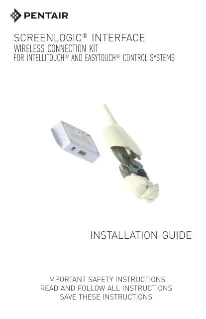
SCREENLOGIC ® INTERFACE<br />
WIRELESS CONNECTION KIT<br />
FOR INTELLITOUCH ® AND EASYTOUCH ® CONTROL SYSTEMS<br />
INSTALLATION GUIDE<br />
IMPORTANT SAFETY INSTRUCTIONS<br />
READ AND FOLLOW ALL INSTRUCTIONS<br />
SAVE THESE INSTRUCTIONS<br />
SCREENLOGIC ® INTERFACE <strong>Wireless</strong> <strong>Connection</strong> Kit <strong>Installation</strong> <strong>Guide</strong>
Technical Support<br />
Sanford, North Carolina (8 A.M. to 4:30 P.M.)<br />
Phone: (800) 831-7133<br />
Fax: (919) 566-8920<br />
Moorpark, California (8 A.M. to 4:30 P.M.)<br />
Phone: (800) 831-7133 (Ext. 6502)<br />
Fax: (805) 530-0194<br />
Web sites: visit www.pentairpool.com and www.staritepool.com<br />
Related manual: <strong>ScreenLogic</strong> ® <strong>Interface</strong> User’s <strong>Guide</strong> (P/N 520493)<br />
Contents<br />
Overview ........................................................................................................... 1<br />
Summary installation steps ............................................................................... 1<br />
In this <strong>Installation</strong> <strong>Guide</strong> ................................................................................... 1<br />
<strong>ScreenLogic</strong> <strong>Interface</strong> <strong>Wireless</strong> <strong>Connection</strong> Kit Contents ............................... 2<br />
Step 1: Mount the Outdoor <strong>Wireless</strong> Transceiver and Connect to the<br />
IntelliTouch or EasyTouch Load Center ........................................................... 3<br />
Step 2: Connect the Indoor <strong>Wireless</strong> Transceiver to the <strong>ScreenLogic</strong><br />
<strong>Interface</strong> Protocol Adapter ................................................................................ 8<br />
FCC Regulatory Safety Notice - This equipment has been tested and found to<br />
comply with the limits for a Class B digital device, pursuant to Part 15 of the FCC<br />
Rules. These limits are designed to provide reasonable protection against harmful<br />
interference in a residential installation. This equipment generates, uses and can<br />
radiate radio frequency energy and, if not installed and used in accordance with the<br />
instructions, may cause harmful interference to radio communications. However,<br />
there is no guarantee that interference will not occur in a particular installation. If this<br />
equipment does cause harmful interference to radio or television reception, which<br />
can be determined by turning the equipment off and on, the user is encouraged to try<br />
to correct the interference by one or more of the following measures:<br />
• Reorient or relocate the receiving antenna.<br />
• Increase the separation between the equipment and receiver.<br />
• Connect the equipment into an outlet on a circuit different from that to<br />
which the receiver is connected.<br />
• Consult the dealer or an experienced radio/TV technician for help.<br />
• Modifications not expressly approved by the party responsible for FCC<br />
compliance could void the user’s authority to operate the equipment.<br />
In this <strong>Installation</strong> <strong>Guide</strong><br />
Use the information in this manual for installing the <strong>ScreenLogic</strong> ® <strong>Interface</strong><br />
<strong>Wireless</strong> <strong>Connection</strong> kit contents.<br />
• For <strong>ScreenLogic</strong> <strong>Interface</strong> system operating instructions, refer to<br />
the <strong>ScreenLogic</strong> <strong>Interface</strong> User’s <strong>Guide</strong> (P/N 520493)<br />
SCREENLOGIC ® INTERFACE <strong>Wireless</strong> <strong>Connection</strong> Kit <strong>Installation</strong> <strong>Guide</strong>
LAN<br />
RESET<br />
1<br />
Overview<br />
The <strong>ScreenLogic</strong> ® <strong>Interface</strong> <strong>Wireless</strong> <strong>Connection</strong> kit consists of two<br />
wireless 2.4 GHz 900 Mhz transceivers which provides a wireless<br />
connection between the <strong>ScreenLogic</strong> <strong>Interface</strong> Protocol adapter and the<br />
IntelliTouch ® or EasyTouch ® Control System Load Center located at the<br />
equipment pad. This wireless connection eliminates the existing hard<br />
wire connection from inside your home to the equipment pad.<br />
<strong>ScreenLogic</strong> <strong>Interface</strong> <strong>Wireless</strong> <strong>Connection</strong> Kit Contents<br />
The following items are included in the <strong>Wireless</strong> <strong>Connection</strong> kit.<br />
• One <strong>ScreenLogic</strong> <strong>Interface</strong> indoor wireless transceiver with AC<br />
power adapter and one foot connection cable with attached plugs.<br />
• One <strong>ScreenLogic</strong> <strong>Interface</strong> outdoor wireless transceiver with 10<br />
foot cable, provided in kit with enclosure and mounting hardware.<br />
• <strong>ScreenLogic</strong> <strong>Interface</strong> <strong>Wireless</strong> <strong>Connection</strong> <strong>Installation</strong> <strong>Guide</strong><br />
(this manual)<br />
Indoor transceiver<br />
AC transformer<br />
Mounting hardware<br />
Transceiver<br />
Enclosure<br />
SERIAL CONNECTION<br />
Black Green Yellow Red<br />
LABEL P/N 520535<br />
Protocol Adapter<br />
P/N 520489<br />
<strong>ScreenLogic</strong><br />
<strong>Interface</strong> Protocol<br />
Adapter (purchased<br />
separately)<br />
Outdoor transceiver<br />
Kit Contents<br />
Transceiver<br />
Enclosure<br />
SCREENLOGIC ® INTERFACE <strong>Wireless</strong> <strong>Connection</strong> Kit <strong>Installation</strong> <strong>Guide</strong>
1<br />
Summary installation steps<br />
The <strong>ScreenLogic</strong> ® <strong>Interface</strong> connection diagram on page 2 shows the<br />
transceiver locations and connections. To install the <strong>ScreenLogic</strong> <strong>Interface</strong><br />
<strong>Wireless</strong> <strong>Connection</strong> kit:<br />
• Mount the transceiver antenna near the IntelliTouch ® or<br />
EasyTouch ® Control System Load Center and connect the<br />
transceiver to the COM port connector located in the IntelliTouch ®<br />
or EasyTouch ® Control System Load Center.<br />
• Use the supplied 12 inch cable to connect the <strong>ScreenLogic</strong><br />
<strong>Interface</strong> indoor wireless transceiver to the <strong>ScreenLogic</strong> <strong>Interface</strong><br />
Protocol adapter. Plug the transceiver AC power adapter into an<br />
AC wall-outlet and into the transceiver unit to power up the unit.<br />
<strong>ScreenLogic</strong> <strong>Interface</strong><br />
Antenna<br />
location<br />
Power LED<br />
RS-485 Connector<br />
(to Protocol Adapter)<br />
RX: This LED is<br />
on when a signal<br />
is being received<br />
from the wireless<br />
transceiver in the<br />
outdoor clam<br />
shell.<br />
TX: This LED is<br />
on when a signal<br />
is being<br />
transmitted to the<br />
wireless<br />
transceiver in the<br />
outdoor clam<br />
shell.<br />
SCREENLOGIC ® INTERFACE <strong>Wireless</strong> <strong>Connection</strong> Kit <strong>Installation</strong> <strong>Guide</strong>
2<br />
INTERNET<br />
RJ11 for DSL<br />
Coax for Cable<br />
Existing wired or<br />
wireless router<br />
(mandatory)<br />
<strong>ScreenLogic</strong> ®<br />
<strong>Interface</strong><br />
<strong>Wireless</strong> router<br />
Transceiver<br />
connected to<br />
<strong>ScreenLogic</strong><br />
<strong>Interface</strong><br />
Protocol adapter<br />
RJ11 RJ45<br />
DSL or<br />
Cable Modem<br />
WAN<br />
1 234<br />
(RJ45)<br />
Ethernet cable<br />
(RJ45 - CAT 5)<br />
In-wall Touch<br />
Screen<br />
4-wire<br />
one foot<br />
cable<br />
- LAN -<br />
1234 WAN<br />
AC power<br />
adapter<br />
Ethernet cable (RJ45 - CAT 5)<br />
Protocol<br />
Adapter<br />
Existing PC<br />
Cable distance limits:<br />
- Ethernet cable distance limit = 300 feet<br />
- Four-wire cable distance limit = 1500 feet<br />
Note: (*) Optional wiring for existing Indoor<br />
Control Panel. Tap into the Indoor Control<br />
Panel connector or pig tail off the four-wire<br />
cable connected to the Personality board.<br />
Waterfall 2<br />
<strong>ScreenLogic</strong> ® <strong>Interface</strong> <strong>Connection</strong> Diagram<br />
Waterfall 2<br />
IntelliTouch ® or<br />
EasyTouch ®<br />
Indoor Control<br />
Panel (*)<br />
<strong>Wireless</strong> transceiver<br />
connected to<br />
Personality board<br />
(COM port)<br />
via 10’ cable<br />
Load Center<br />
(Located outside at<br />
equipment pad)<br />
SCREENLOGIC ® INTERFACE <strong>Wireless</strong> <strong>Connection</strong> Kit <strong>Installation</strong> <strong>Guide</strong>
3<br />
Step 1:<br />
Mount the Outdoor <strong>Wireless</strong> Transceiver and Connect to the<br />
IntelliTouch ® or EasyTouch ® Control System Load Center<br />
The following describes how to mount the transceiver the IntelliTouch ® or<br />
EasyTouch ® Control System Load Center and connect the four-wire cable<br />
to the COM port connector located in the IntelliTouch or EasyTouch<br />
Control System Load Center:<br />
Mount the Transceiver Module<br />
The Transceiver is a two-way radio device with an attached antenna that<br />
communicates to and from the IntelliTouch or EasyTouch Control System.<br />
Mount the transceiver at a convenient location (on a flat vertical surface) near<br />
the load center, at a minimum of 5 ft. above ground level to optimize the<br />
transmit and receive operating range.<br />
1. Remove the two retaining screws located on the underside of the<br />
transceiver case. Slide the case off the back plate.<br />
2. Position the back plate against the mounting surface so that the<br />
transceiver is oriented in an upright position (with the antenna<br />
pointing upwards). Use a pencil to mark the four mounting points.<br />
Drill four 3/16 in. diameter holes into the mounting surface and<br />
insert the four plastic anchors (provided in the kit).<br />
Note: To avoid signal interference, mount the transceiver a<br />
minimum of 10 feet away from the load center, any metal<br />
surface/structure, or air blower located in the immediate area<br />
of the equipment pad.<br />
3. Position the back plate over the mounting points and secure it with<br />
the four mounting screws (provided in the kit).<br />
4. Carefully position the transceiver circuit board into the mounted<br />
back plate. Route the connection wire down through the lower exit<br />
hole (left side) at the bottom of the back plate. Carefully pull the<br />
wire out the lower hole and position the circuit board in the back<br />
plate.<br />
5. Position the transceiver circuit board to the left side of the back<br />
plate, and slide the case over the circuit board and antenna into<br />
the back plate. Secure the circuit board in the case using the two<br />
retaining screws.<br />
6. Proceed to “Connect the Transceiver connection cable to the<br />
COM Port on Control Systems Circuit Board” on the next page.<br />
SCREENLOGIC ® INTERFACE <strong>Wireless</strong> <strong>Connection</strong> Kit <strong>Installation</strong> <strong>Guide</strong>
4<br />
Case<br />
Back plate<br />
mounting<br />
point (4x)<br />
Transceiver Circuit board<br />
Transceiver Connector<br />
Transceiver case<br />
retaining screws<br />
(x2)<br />
YEL<br />
BLK<br />
RED<br />
GRN<br />
RED (15 V - PIN 4)<br />
YEL (+ DT - PIN 3)<br />
GRN (- DT - PIN 2)<br />
BLK (GND - PIN 1)<br />
COM PORT screw terminal<br />
connector on IntelliTouch ®<br />
or EasyTouch ® Control<br />
System circuit board<br />
Transceiver Module Wiring<br />
SCREENLOGIC ® INTERFACE <strong>Wireless</strong> <strong>Connection</strong> Kit <strong>Installation</strong> <strong>Guide</strong>
5<br />
Connect the Transceiver connection cable to the COM Port on Control<br />
System Circuit Board<br />
WARNING Switch OFF the main system power to the Load Center<br />
before making any connections.<br />
1. Unlatch the enclosure door spring latche(s), and open the door.<br />
2. Remove the two retaining screws securing the high voltage coverpanel,<br />
and remove it from the enclosure.<br />
3. Loosen the two access screws securing the control panel.<br />
Access<br />
screw<br />
Access<br />
screw<br />
Control panel<br />
Panel retaining<br />
screw<br />
(Cover-panel<br />
not shown)<br />
Retaining<br />
screw<br />
IntelliTouch ® or EasyTouch ® Load Center<br />
4. Lower down the hinged control panel to access the circuit board.<br />
SCREENLOGIC ® INTERFACE <strong>Wireless</strong> <strong>Connection</strong> Kit <strong>Installation</strong> <strong>Guide</strong>
6<br />
5. Route the four conductor transceiver connection cable into the<br />
lower plastic grommet, up through the low voltage raceway to the<br />
circuit board.<br />
Circuit board<br />
Control panel<br />
Raceway<br />
6. Insert the four wires into the screw terminals of the COM PORT<br />
plug located on the circuit board as shown on page 6. Using a<br />
small flat-blade screwdriver, secure the wires with the screws.<br />
Make sure to match the color coding of the four wires:<br />
Pin 4 - Red = +15<br />
Pin 3 - Yellow = +DT<br />
Pin 2 - Green = -DT<br />
Pin 1 - Black = GND<br />
Note: Multiple wires may be<br />
inserted into a single screw<br />
terminal but increases the<br />
chances of a poor or intermittent<br />
connection.<br />
IntelliTouch ® or<br />
EasyTouch ® Control<br />
System COM Ports<br />
(J7/J8) screw terminal<br />
connector<br />
BLK<br />
GRN<br />
YEL<br />
RED<br />
SCREENLOGIC ® INTERFACE <strong>Wireless</strong> <strong>Connection</strong> Kit <strong>Installation</strong> <strong>Guide</strong>
7<br />
Note: Install the <strong>ScreenLogic</strong> ® <strong>Interface</strong> outdoor<br />
wireless transceiver within 10 feet from Load Center<br />
Transceiver Circuit board<br />
Transceiver Connector<br />
YEL<br />
BLK<br />
RED<br />
GRN<br />
RED (15 V - PIN 4)<br />
YEL (+ DT - PIN 3)<br />
GRN (- DT - PIN 2)<br />
BLK (GND - PIN 1)<br />
COM PORT screw terminal<br />
connector on IntelliTouch ®<br />
or EasyTouch ® Control<br />
System circuit board<br />
7. After the connection has been completed, close the control panel<br />
into its original position and secure it with the two access screws.<br />
8. Install the front panel and secure it with the two retaining screws.<br />
9. Close the Load Center front door. Fasten the spring latche(s).<br />
10. Switch the power on to the IntelliTouch ® or EasyTouch ® Control<br />
System Load Center.<br />
11. Proceed to the “Connect the <strong>ScreenLogic</strong> <strong>Interface</strong> Indoor<br />
<strong>Wireless</strong> Transceiver to the <strong>ScreenLogic</strong> <strong>Interface</strong> Protocol<br />
Adapter” on page 8.<br />
SCREENLOGIC ® INTERFACE <strong>Wireless</strong> <strong>Connection</strong> Kit <strong>Installation</strong> <strong>Guide</strong>
8<br />
Step 2:<br />
Connect the <strong>ScreenLogic</strong> ® <strong>Interface</strong> Indoor <strong>Wireless</strong> Transceiver to the<br />
<strong>ScreenLogic</strong> <strong>Interface</strong> Protocol Adapter<br />
To connect the <strong>ScreenLogic</strong> <strong>Interface</strong> indoor wireless transceiver to the<br />
<strong>ScreenLogic</strong> <strong>Interface</strong> Protocol adapter:<br />
1. Using the provided connection cable, connect one end of the<br />
cable to the <strong>ScreenLogic</strong> <strong>Interface</strong> Protocol adapter and the other<br />
end to the <strong>ScreenLogic</strong> <strong>Interface</strong> indoor wireless transceiver. The<br />
cable plugs are keyed for easy connection.<br />
2. Plug the <strong>ScreenLogic</strong> <strong>Interface</strong> <strong>Wireless</strong> <strong>Connection</strong> transceiver<br />
AC adapter wall-plug into an AC grounded electrical outlet.<br />
1 ft. connection cable<br />
(provide in kit)<br />
LABEL P/N 520535<br />
SERIAL CONNECTION<br />
Black Green Yellow Red<br />
LAN<br />
RESET<br />
Protocol Adapter<br />
P/N 520489<br />
<strong>ScreenLogic</strong> <strong>Interface</strong><br />
Protocol Adapter<br />
<strong>ScreenLogic</strong> <strong>Interface</strong> Indoor<br />
<strong>Wireless</strong> Transceiver<br />
Transceiver Indoor wireless transceiver<br />
RED RED<br />
YELLOW YELLOW<br />
GREEN GREEN<br />
BLACK BLACK<br />
Wiring Configuration<br />
SCREENLOGIC ® INTERFACE <strong>Wireless</strong> <strong>Connection</strong> Kit <strong>Installation</strong> <strong>Guide</strong>
1620 HAWKINS AVE., SANFORD, NC 27330 • (919) 566-8000<br />
10951 WEST LOS ANGELES AVE., MOORPARK, CA 93021 • (805) 553-5000<br />
WWW.PENTAIRPOOL.COM<br />
All <strong>Pentair</strong> trademarks and logos are owned by <strong>Pentair</strong>, Inc. <strong>Pentair</strong> Aquatic Systems,<br />
<strong>ScreenLogic</strong> ® , EasyTouch ® and IntelliTouch ® are trademarks and/or registered trademarks of<br />
<strong>Pentair</strong> Water Pool and Spa, Inc. and/or its affiliated companies in the United States and/ or<br />
other countries. iPhone ® is a registered trademark of Apple Corporation. Unless expressly<br />
noted, names and brands of third parties that may be used in this document are not used to<br />
indicate an affiliation or endorsement between the owners of these names and brands and<br />
<strong>Pentair</strong> Water Pool and Spa, Inc. Those names and brands may be the trademarks or registered<br />
trademarks of those third parties. Because we are continuously improving our products and<br />
services, <strong>Pentair</strong> reserves the right to change specifications without prior notice. <strong>Pentair</strong> is an<br />
equal opportunity employer.<br />
© 2013 <strong>Pentair</strong> Aquatic Systems. All rights reserved.<br />
This document is subject to change without notice.<br />
*521965*<br />
P/N 521965 REV. B 4/13<br />
SCREENLOGIC ® INTERFACE <strong>Wireless</strong> <strong>Connection</strong> Kit <strong>Installation</strong> <strong>Guide</strong>