FullFloXF Backwash Valve Installation and User's Guide - Pentair
FullFloXF Backwash Valve Installation and User's Guide - Pentair
FullFloXF Backwash Valve Installation and User's Guide - Pentair

You also want an ePaper? Increase the reach of your titles
YUMPU automatically turns print PDFs into web optimized ePapers that Google loves.
<strong>FullFloXF</strong> <br />
<strong>Backwash</strong> <strong>Valve</strong><br />
<strong>Installation</strong><br />
<strong>and</strong><br />
User’s <strong>Guide</strong><br />
IMPORTANT SAFETY INSTRUCTIONS<br />
READ AND FOLLOW ALL INSTRUCTIONS<br />
SAVE THESE INSTRUCTIONS
Customer Service / Technical Support<br />
i<br />
If you have questions about ordering <strong>Pentair</strong> Water Pool <strong>and</strong> Spa (“<strong>Pentair</strong>”) replacement parts, <strong>and</strong> pool products,<br />
please use the following contact information:<br />
Customer Service (8 A.M. to 5 P.M. — Eastern <strong>and</strong><br />
Pacific Times)<br />
Phone: (800) 831-7133<br />
Fax: (800) 284-4151<br />
Web site<br />
visit www.pentairpool.com or www.staritepool.com to<br />
find information about <strong>Pentair</strong> products.<br />
Technical Support<br />
Sanford, North Carolina (8 A.M. to 5 P.M. ET)<br />
Phone: (919) 566-8000<br />
Fax: (919) 566-8920<br />
Moorpark, California (8 A.M. to 5 P.M. PT)<br />
Phone: (805) 553-5000 (Ext. 5591)<br />
Fax: (805) 553-5515<br />
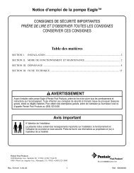
Table of Contents<br />
General <strong>Installation</strong> Information .......................<br />
Important Warning <strong>and</strong> Safety Instructions .....<br />
<strong>Installation</strong> <strong>and</strong> Operation ................................<br />
<strong>Valve</strong> Connection <strong>and</strong> Filter Position<br />
Installing the <strong>Valve</strong> onto the Filter<br />
Important <strong>Installation</strong> <strong>Guide</strong>lines<br />
Normal Operation<br />
<strong>Backwash</strong>ing<br />
Servicing .............................................................<br />
Removing Diverters for Inspection<br />
or Service<br />
i<br />
ii<br />
1<br />
1<br />
2<br />
2<br />
2<br />
2<br />
3<br />
3<br />
Cleaning <strong>and</strong>/or Replacing O- Rings on<br />
Diverter <strong>and</strong> End Cap<br />
<strong>Valve</strong> Reassembly<br />
Maintenance ......................................................<br />
<strong>Valve</strong> Care<br />
Winterizing<br />
Troubleshooting ................................................<br />
<strong>Valve</strong> Dimensions ..............................................<br />
Replacement Parts ............................................<br />
Illustrated Parts List<br />
<strong>Valve</strong> Head Loss Curves<br />
3<br />
4<br />
5<br />
5<br />
5<br />
6<br />
6<br />
7<br />
7<br />
7<br />
Cleaning <strong>and</strong>/or Replacing Diverters<br />
3<br />
<strong>Valve</strong> Connections: Quick Reference <strong>Guide</strong><br />
8<br />
General <strong>Installation</strong> Information<br />
The following information should be read carefully since<br />
it outlines the proper manner of care <strong>and</strong> operation for<br />
your filter system.<br />
You can expect maximum efficiency <strong>and</strong> life from your<br />
filtration system by following these instructions <strong>and</strong> taking<br />
the necessary preventative care.<br />
• Have a trained pool professional perform all pressure<br />
tests.<br />
• Do not connect the system to a high pressure or<br />
city water system.<br />
• Trapped air in the system can create a hazardous<br />
condition. BE SURE to purge all air from the system<br />
before operating or testing equipment.<br />
• DO NOT pressure test with compressed air!<br />
• Piping must conform to local/state plumbing <strong>and</strong><br />
sanitary codes.<br />
• Support piping independently to prevent strains<br />
on filter or valve.<br />
• Fittings restrict flow; for best efficiency, use the<br />
fewest possible fittings.<br />
• A check valve installed ahead of the filter inlet will<br />
prevent contaminants from draining back into the<br />
pool.<br />
• A check valve installed between the filter <strong>and</strong><br />
heater will prevent hot water from backing up into<br />
the filter <strong>and</strong> deforming the internal components.<br />
• All wiring, grounding <strong>and</strong> bonding of associated<br />
equipment must meet local <strong>and</strong>/or National Electrical<br />
Code st<strong>and</strong>ards.<br />
For information about the Virginia Graeme Baker Pool <strong>and</strong> Spa Safety Act, contact the Consumer Product Safety<br />
Commission at (301) 504-7908 or visit www.cpsc.gov.<br />
Important Note: Always turn off all power to the pool pump before installing the cover or working on any suction outlet.<br />
P/N 270505 Rev. B 4/19/12<br />
<strong>FullFloXF</strong> <strong>Backwash</strong> <strong>Valve</strong> <strong>Installation</strong> <strong>and</strong> User’s <strong>Guide</strong>
ii<br />
IMPORTANT WARNING AND SAFETY INSTRUCTIONS<br />
Important Notice:<br />
This guide provides installation <strong>and</strong> operation instructions for the<br />
<strong>FullFloXF</strong> <strong>Backwash</strong> <strong>Valve</strong>. Consult <strong>Pentair</strong> with any questions<br />
regarding this equipment.<br />
Attention Installer: This guide contains important information about<br />
the installation, operation <strong>and</strong> safe use of this product. This information<br />
should be given to the owner <strong>and</strong>/or operator of this equipment after<br />
installation or left on or near the valve.<br />
Attention User: This manual contains important information that<br />
will help you in operating <strong>and</strong> maintaining this valve. Please retain it for<br />
future reference.<br />
Before installing this product, read <strong>and</strong> follow all<br />
warning notices <strong>and</strong> instructions which are included.<br />
Failure to follow safety warnings <strong>and</strong> instructions can result in severe<br />
injury, death, or property damage. Call (800) 831-7133 for additional free<br />
copies of these instructions.<br />
Consumer Information <strong>and</strong> Safety<br />
The <strong>FullFloXF</strong> <strong>Backwash</strong> <strong>Valve</strong> is designed <strong>and</strong> manufactured to provide<br />
many years of safe <strong>and</strong> reliable service when installed, operated <strong>and</strong><br />
maintained according to the information in this manual <strong>and</strong> the installation<br />
codes referred to in later sections. Throughout the manual, safety warnings<br />
<strong>and</strong> cautions are identified by the “ ” symbol. Be sure to read <strong>and</strong><br />
comply with all of the warnings <strong>and</strong> cautions.<br />
SERIOUS BODILY INJURY OR DEATH CAN<br />
RESULT IF THIS VALVE IS NOT INSTALLED<br />
AND USED CORRECTLY.<br />
INSTALLERS, POOL OPERATORS AND<br />
POOL OWNERS MUST READ THESE<br />
WARNINGS AND ALL INSTRUCTIONS<br />
BEFORE USING THIS VALVE.<br />
This valve is intended for use in swimming pool<br />
applications. Most states <strong>and</strong> local codes regulate<br />
the construction, installation, <strong>and</strong> operation of public pools <strong>and</strong> spas,<br />
<strong>and</strong> the construction of residential pools <strong>and</strong> spas. It is important to<br />
comply with these codes, many of which directly regulate the installation<br />
<strong>and</strong> use of this product. Consult your local building <strong>and</strong> health codes<br />
for more information.<br />
To reduce risk of injury, do not permit children to<br />
use or operate this valve.<br />
When setting up pool turnovers or flow rates the<br />
operator must consider local codes governing<br />
turnovers as well as disinfectant feed ratios.<br />
DO NOT increase pump size; this will increase<br />
the flow rate through the circulating system <strong>and</strong><br />
may exceed the maximum flow rate stated on the<br />
drain cover.<br />
Pumps are not a substitute for properly installed<br />
<strong>and</strong> secured pool drain covers. An ANSI/ASME<br />
A112.19.8 approved anti-entrapment drain cover must be used for each<br />
drain. Pools <strong>and</strong> spas should utilize a minimum of two drains per pump.<br />
If a drain cover becomes loose, broken or is missing, close the pool or<br />
spa immediately <strong>and</strong> shut off the pump until an approved anti-entrapment<br />
drain cover is properly installed with the manufacturer’s supplied screw.<br />
<strong>FullFloXF</strong> <strong>Backwash</strong> <strong>Valve</strong> <strong>Installation</strong> <strong>and</strong> User’s <strong>Guide</strong><br />
FILTER OPERATES UNDER HIGH PRESSURE.<br />
When any part of the circulating system, (e.g., clamp,<br />
pump, filter, valve(s), etc.), is serviced, air can enter<br />
the system <strong>and</strong> become pressurized. Pressurized<br />
air can cause the lid to separate which can result in<br />
severe injury, death, or property damage.<br />
To avoid this potential hazard, follow these instructions:<br />
1. Before repositioning valve(s) <strong>and</strong> before beginning the assembly,<br />
disassembly, or adjustment of the clamp or any other service of the<br />
circulating system: (A) Turn the pump OFF <strong>and</strong> shut OFF any automatic<br />
controls to ensure the system is NOT inadvertently started during the<br />
servicing; (B) open the manual air relief valve; (C) st<strong>and</strong> clear of the<br />
filter; (D) wait until all pressure is relieved.<br />
2. Whenever installing the filter clamp FOLLOW THE FILTER CLAMP<br />
INSTALLATION INSTRUCTIONS EXACTLY.<br />
3. Once service on the circulating system is complete FOLLOW SYSTEM<br />
RESTART INSTRUCTIONS EXACTLY.<br />
4. Maintain circulation system properly. Replace worn or damaged parts<br />
immediately, (e.g., clamp, pressure gauge, valve(s), o-rings, etc).<br />
5. Be sure that the filter is properly mounted <strong>and</strong> positioned according<br />
to instructions provided.<br />
The valve must be installed by a qualified pool<br />
serviceman in accordance with the National<br />
Electrical Code <strong>and</strong> all applicable local codes <strong>and</strong><br />
ordinances. Always disconnect power to the pool<br />
equipment at the circuit breaker before servicing<br />
any of the equipment. Be sure that the disconnected circuit is locked<br />
out or properly tagged so that it cannot be switched on while you are<br />
working on the pool equipment. Failure to do so could result in serious<br />
injury or death to serviceman, pool users or others due to electric<br />
shock. Position the filter <strong>and</strong> the air relief valve to safely direct water<br />
drainage <strong>and</strong> purged air or water. Water discharged from an improperly<br />
positioned filter or valve can create an electrical hazard that can cause<br />
severe personal injury as well as damage property.<br />
A pool or spa pump must be installed by a qualified<br />
pool <strong>and</strong> spa service professional in accordance<br />
with the National Electrical Code <strong>and</strong> all applicable local codes <strong>and</strong><br />
ordinances. Improper installation may create an electrical hazard which<br />
could result in death or serious injury to pool users, installers, or others<br />
due to electrical shock, <strong>and</strong> may also cause damage to property.<br />
For filters intended for use in other than single-family<br />
dwellings, a clearly labeled emergency switch shall<br />
be provided as part of the installation. The switch shall be readily<br />
accessible to the occupants <strong>and</strong> shall be installed at least 5 feet<br />
(1.52 m) away, adjacent to, <strong>and</strong> within sight of, the valve.<br />
Water temperature in excess of 100°F (37.7°C) may<br />
be hazardous to your health. Prolonged immersion<br />
in hot water may induce hyperthermia. Hyperthermia occurs when the<br />
internal temperature of the body reaches several degrees above normal<br />
body temperature of 98.6°F (37°). Effects of hyperthermia include: (1)<br />
Unawareness of impending danger. (2) Failure to perceive heat. (3)<br />
Failure to recognize the need to leave the spa. (4) Physical inability to<br />
exit the spa. (5) Fetal damage in pregnant women. (6) Unconsciousness<br />
resulting in danger of drowning. The use of alcohol, drugs, or medication<br />
can greatly increase the risk of fatal hyperthermia in hot tubs <strong>and</strong> spas.
<strong>Installation</strong> <strong>and</strong> Operation<br />
1<br />
Do not operate this unit above the maximum operating pressure of the valve or the filter. Operating your system above maximum<br />
recommended pressure may cause your filter or valve to separate <strong>and</strong> result in severe injury, death, <strong>and</strong> property damage. Never<br />
connect the filter <strong>and</strong> valve unit to a pump, which can generate a pressure that exceeds the operating<br />
pressure of the filter or valve.<br />
Chemical fumes <strong>and</strong>/or spills can severely damage the structural components of the filter or valve. Structurally weakened<br />
components can cause the valve or the filter lid to separate <strong>and</strong> result in severe bodily injury, death, <strong>and</strong> property damage.<br />
If the valve is hard to rotate, shut the pump off before rotating between positions. Do not use excessive force. If shutting off the<br />
pump does not ease the rotation, service the valve as described in this manual. There may be foreign objects obstructing one of<br />
the internal components.<br />
Be careful not to allow any glue to get into the central bore of the valve body, as this can damage the internal components.<br />
Do not use excess amounts of glue.<br />
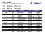
<strong>Valve</strong> Connection <strong>and</strong> Filter Position<br />
1. The images below show the valve orientations that<br />
correspond to filter inlet position (depends if the<br />
inlet is on the top or the bottom).<br />
2. Align the valve with the filter tank according<br />
to the part numbers listed below. Push the<br />
valve into the ports <strong>and</strong> turn the bulkhead nuts<br />
snugly on the tank fittings. H<strong>and</strong> tighten the<br />
nuts - no tools are required.<br />
<strong>Valve</strong> Position: Filter Inlet on BOTTOM<br />
<strong>Valve</strong> Part Numbers: Filter Inlet on BOTTOM<br />
To Pool<br />
P/N 263081<br />
<strong>Pentair</strong><br />
P/N 262508<br />
Sta-Rite<br />
From<br />
Pump<br />
Filter Inlet<br />
<strong>Valve</strong> Position: Filter Inlet on TOP<br />
P/N 262512<br />
<strong>FullFloXF</strong><br />
<strong>Valve</strong> Part Numbers: Filter Inlet on TOP<br />
P/N 262511<br />
No Fittings<br />
Filter Inlet<br />
From<br />
Pump<br />
P/N 263080<br />
<strong>Pentair</strong><br />
P/N 262507<br />
Sta-Rite<br />
To Pool<br />
P/N 262509<br />
No Fittings<br />
<strong>FullFloXF</strong> <strong>Backwash</strong> <strong>Valve</strong> <strong>Installation</strong> <strong>and</strong> User’s <strong>Guide</strong>
OFF<br />
2<br />
Installing the <strong>Valve</strong> onto the Filter<br />
1. Turn off all power to the system.<br />
For retrofit installations only, follow steps a-d.<br />
For new installations, proceed to Step 2.<br />
a. Open the pressure relief valve on the top of<br />
the filter. St<strong>and</strong> clear while air is released from<br />
the system.<br />
b. If the filter is below pool level, close the suction<br />
<strong>and</strong> return line valves to isolate the filtration<br />
system.<br />
c. Remove the drain plug from the filter to drain<br />
the water from the filter.<br />
d. Remove existing valve from the filter.<br />
2. Place O-rings on the face of the union fittings,<br />
where the face of the backwash valve union will<br />
connect to the filter bulkheads. Be sure O-Ring is<br />
seated into the groove of each union piece.<br />
1<br />
Union Nut<br />
Adapter<br />
2<br />
Important <strong>Installation</strong> <strong>Guide</strong>lines<br />
1. Piping size: 2-1/2” or 3” CPVC/PVC pipe fittings -<br />
can be plumbed directly into valve port socket. 3”<br />
plumbing requires a 3” coupling or 90° elbow slipped<br />
over the valve port spigot. (Also can be used with<br />
any size PVC plumbing with appropriate adapters).<br />
Note: Be sure that no glue enters inside of valve<br />
body past the ports. The recommended pipe glue<br />
to use is WELD-ON ® 724 CPVC, GRAY or glue<br />
types such as WELD-ON ® 790 MULTI-PURPOSE<br />
SOLVENT CEMENT.<br />
2. Support piping in such a way that strain is not<br />
placed on the valve or filter.<br />
3. The maximum operating pressure of this valve is<br />
50 psi. The filter unit also has a maximum operating<br />
pressure listed on the filter nameplate.<br />
Normal Operation<br />
1. Be sure the valve h<strong>and</strong>le is pointing towards FILTER.<br />
2. Turn on the filter pump. Check the system for<br />
normal water flow.<br />
3<br />
Retainer<br />
Ring<br />
4<br />
XF Union <strong>Installation</strong><br />
Union Nut<br />
<strong>Backwash</strong>ing<br />
1. Turn off all system pump(s).<br />
2. Release all pressure from the system at the<br />
main filter.<br />
3. Turn the valve h<strong>and</strong>le to the BACKWASH<br />
position.<br />
4. Turn on the system pump(s) <strong>and</strong> run the system<br />
until the water runs clean.<br />
5. Turn off all system pump(s).<br />
6. Return the valve h<strong>and</strong>le to the FILTER position.<br />
7. Turn on system pump(s) <strong>and</strong> check for normal<br />
water flow.<br />
3-Way <strong>Valve</strong><br />
O-Ring<br />
Spa<br />
Pool<br />
Sta-Rite Union <strong>Installation</strong><br />
3. Holding the valve upright, place onto the filter<br />
bulkheads. Tighten both union nuts to secure the<br />
valve on the filter.<br />
4. Plumb the discharge of the pump into the valve<br />
inlet labeled FILTER INLET.<br />
5. Plumb the valve outlet labeled FILTER OUTLET<br />
to the heater or pool return lines.<br />
6. Plumb the WASTE ports as needed. Let the<br />
system dry for 24 hours.<br />
<strong>FullFloXF</strong> <strong>Backwash</strong> <strong>Valve</strong> <strong>Installation</strong> <strong>and</strong> User’s <strong>Guide</strong><br />
Filter Pump<br />
Pump Inlet<br />
(From Pump)<br />
Pump Outlet<br />
(Pool Return)<br />
To Waste<br />
Normal Operation<br />
Filter<br />
<strong>Backwash</strong> <strong>Valve</strong>
Servicing<br />
3<br />
Incorrect assembly of the internal components may cause your filter to dead head <strong>and</strong> could cause severe bodily <strong>and</strong>/or property<br />
damage.<br />
Use only use silicone based lubricants on the valve, other types of lubricant may damage the plastic or rubber components.<br />
Removing Diverters for Inspection or Service<br />
1. Shut off the pump <strong>and</strong> open the manual relief valve on<br />
the filter to relieve all internal pressure.<br />
2. If the filter is below the pool water level, close the<br />
suction <strong>and</strong> the return line valves to isolate the filtration<br />
equipment.<br />
3. Drain the filter by moving the valve h<strong>and</strong>le to the<br />
backwash position <strong>and</strong> removing the filter drain plug.<br />
4. Remove the h<strong>and</strong>le by firmly pulling the h<strong>and</strong>le straight up.<br />
5. Pull the tabs (if needed, insert two flat head screwdrivers<br />
behind the tabs) <strong>and</strong> rotate the top counter-clockwise<br />
to unlock. Remove the end cap.<br />
6. Slowly pull out the diverter assembly.<br />
Note which diverter is on the top before reassembling.<br />
Cleaning <strong>and</strong>/or Replacing the Diverters<br />
Removing the H<strong>and</strong>le<br />
1. DOW CORNING ® 111 LUBRICANT or similar lubricant<br />
is recommended as a seal lubricant.<br />
Note: This lubricant is formulated to seal surfaces <strong>and</strong><br />
extends the lubrication period. Many other lubricants<br />
are broken down quickly by pool water <strong>and</strong> have a short<br />
lubricating life.<br />
2. Inspect all seals for nicks <strong>and</strong> cuts. Replace diverter<br />
if damaged.<br />
3. Inspect the bore of the valve especially around the<br />
ports. Deep scratches <strong>and</strong> cuts in this area may cause<br />
leaks from the waste port. Replace valve if damaged.<br />
4. Using a clean cloth, thoroughly clean all seals <strong>and</strong> the<br />
bore of the valve.<br />
5. Apply liberal amounts of DOW CORNING ® 111<br />
LUBRICANT or similar lubricant to the surface of all<br />
seals.<br />
Cleaning <strong>and</strong>/or Replacing the O-Rings on<br />
Diverter <strong>and</strong> End Cap<br />
1. Without over-stretching, remove <strong>and</strong> clean O-rings with<br />
a clean cloth.<br />
2. Clean the O-ring grooves with a clean cloth.<br />
3. Apply liberal amounts of DOW CORNING ® 111<br />
LUBRICANT or similar seal lubricant to the O-rings.<br />
4. Replace the O-rings in their grooves.<br />
Removing the End Cap<br />
Cleaning the O-Ring<br />
End Cap<br />
End Cap O-Ring<br />
Diverter O-Ring<br />
<strong>FullFloXF</strong> <strong>Backwash</strong> <strong>Valve</strong> <strong>Installation</strong> <strong>and</strong> User’s <strong>Guide</strong>
4<br />
<strong>Valve</strong> Reassembly<br />
1. Insert the outlet diverter into the center diverter.<br />
Align the three keys as shown below.<br />
2. Insert the inlet diverter into the center diverter.<br />
Align the fins as shown below.<br />
3. Insert spring <strong>and</strong> seal into the correct key of the<br />
center diverter. Follow either configuration A or B<br />
below, based on the model part number:<br />
A. Inlet on TOP: P/N 263080, 262507, 262509<br />
B. Inlet on BOTTOM: P/N 263081, 262508, 262511, 262512<br />
Note: There are two possible positions for the seal,<br />
the text on the center diverters states which side to<br />
place the seal.<br />
4. Lubricate all sealing surfaces on the seal <strong>and</strong> diverters<br />
with DOW CORNING ® 111 LUBRICANT or similar<br />
lubricant.<br />
5. Slide the diverter assembly into the body of the valve.<br />
Follow configuration A or B below.<br />
6. Align the arrow <strong>and</strong> notch on the end cap <strong>and</strong> body.<br />
7. Press the cap on <strong>and</strong> turn clockwise until the side<br />
snaps are locked into place.<br />
Note: End caps only fit one way <strong>and</strong> must be locked<br />
into place.<br />
8. Partially install the h<strong>and</strong>le <strong>and</strong> rotate until the arrow<br />
on the h<strong>and</strong>le is between the two arrows on end<br />
cap.<br />
9. Press the h<strong>and</strong>le until it is locked into place.<br />
10. Inspect the valve. When valve is in the filter position,<br />
the waste port should be blocked off with the waste<br />
seal.<br />
1 & 2 3<br />
Inlet<br />
Diverter<br />
A. Inlet on TOP<br />
Waste<br />
Seal<br />
6<br />
Align the notch on the end cap with the arrow.<br />
Fins<br />
to align<br />
Center<br />
Diverter<br />
Spring<br />
B. Inlet on BOTTOM<br />
Keys<br />
to align<br />
Spring<br />
7<br />
Press the cap down <strong>and</strong> turn clockwise.<br />
Outlet<br />
Diverter<br />
Waste<br />
Seal<br />
5<br />
A. Inlet on TOP<br />
B. Inlet on BOTTOM<br />
Outlet<br />
Diverter<br />
Inlet<br />
Diverter<br />
Inlet<br />
Diverter<br />
Outlet<br />
Diverter<br />
8<br />
Install h<strong>and</strong>le. Rotate until arrow on h<strong>and</strong>le is<br />
between the ‘Filter’ <strong>and</strong> ‘<strong>Backwash</strong>’ arrows.<br />
FILTER<br />
BACKWASH<br />
<strong>FullFloXF</strong> <strong>Backwash</strong> P/N 263081, <strong>Valve</strong> 262508, <strong>Installation</strong> P/N <strong>and</strong> 263080, User’s 262507, <strong>Guide</strong><br />
262511, 262512<br />
262509<br />
(Inlet on BOTTOM)<br />
(Inlet on TOP)
Maintenance<br />
5<br />
Continuing to operate a valve with damaged components could result in sudden failure of valve structural components, which<br />
could possibly cause flooding or serious personal injury due to a sudden release of filter system pressure. Inspect <strong>and</strong> service<br />
your valve regularly as described in this section.<br />
To extend valve life, periodically inspect shaft seals <strong>and</strong> valve bore for dirt <strong>and</strong> clean as described in the Servicing section on<br />
page 3. To extend seal life, remove diverters <strong>and</strong> lubricate periodically.<br />
<strong>Valve</strong> Care<br />
Proper care <strong>and</strong> valve maintenance will add many years<br />
of service to the pool. The service life of the valve is<br />
determined by factors such as dirt, heat, weather<br />
exposure, etc.<br />
Follow the suggestions described in this section to<br />
maximize the life of the valve.<br />
1. Dirt<br />
Dirt particles may accumulate on the seals <strong>and</strong><br />
can scratch the valve body during normal filter<br />
operation <strong>and</strong> backwashing.<br />
These scratches can accumulate on the bore<br />
which cannot be repaired.<br />
Replace valve or diverters when the seals can no<br />
longer function properly from dirt accumulation<br />
2. Heat<br />
This valve is not damaged by temperatures found<br />
in correctly plumbed pool <strong>and</strong> spa installations.<br />
Heat damage can be caused by:<br />
• Improper heater installation or operation:<br />
Heaters should be located after the pool<br />
filtration equipment <strong>and</strong> must have a check<br />
valve or similar device that ensures super<br />
heated water cannot backup into the valve<br />
when the pump is switched off.<br />
• Circulation pump operating with no flow:<br />
Pumps transfer heat into the water; if there<br />
is no water flow due to a closed valve or loss<br />
of prime, water in the pump will become very<br />
hot <strong>and</strong> can damage any pool equipment inline<br />
<strong>and</strong> close to the pump.<br />
• Always be sure the system valves are open<br />
so that water is free to flow through the pool<br />
equipment.<br />
3. Weather Exposure<br />
All materials are affected to some degree by weather<br />
exposure. Materials used in this valve are suitable<br />
for outdoor use.<br />
• To extend valve life, protect from weathering,<br />
especially direct sunlight.<br />
• Years of outdoor exposure can cause materials<br />
to become structurally weakened.<br />
• Always replace valve components that show<br />
signs of deterioration, such as cracked surfaces<br />
<strong>and</strong>/or significant discoloration.<br />
4. Chemical Damage<br />
• Maintain pool water chemistry properly. Pool<br />
chemistry is a specialized area <strong>and</strong> you should<br />
consult your pool service specialist for specific<br />
details.<br />
• Always introduce chemicals into the pool after<br />
water flow passes through the pool filtration<br />
equipment.<br />
• Use only silicone based lubricants. Other<br />
lubricants may damage valve components.<br />
• Always install a check valve between in-line<br />
chlorinators <strong>and</strong> pool equipment to prevent<br />
chlorine gas from backing up into the pool<br />
equipment.<br />
5. Lubrication<br />
Thick silicone grease allows O -rings to glide easily<br />
over stationary plastic surfaces. Lubrication makes<br />
h<strong>and</strong>le actuation easy <strong>and</strong> ensures seals are not<br />
damaged when passing over internal passageways<br />
in the valve.<br />
• Frequency of lubrication depends on:<br />
--<br />
Frequency of actuation<br />
--<br />
Water chemistry<br />
--<br />
Water quality<br />
--<br />
Water temperature<br />
• Inspect seals <strong>and</strong> the small shaft seal after three<br />
(3) months to be sure they are well lubricated.<br />
• <strong>Valve</strong> may be reassembled <strong>and</strong> checked again<br />
in three (3) more months.<br />
• O-rings that have been cut, nibbled out, or<br />
twisted may be signs of inadequate lubrication.<br />
Damaged O-rings must be replaced.<br />
Winterizing<br />
1. Consult your filter operation <strong>and</strong> user’s manual<br />
for winterizing instructions.<br />
2. If possible, remove, clean <strong>and</strong> lubricate the<br />
O-rings <strong>and</strong> diverters as described on page 3.<br />
3. Store the parts in an airtight container or sealed<br />
plastic bag that protects from light <strong>and</strong> air.<br />
4. Store away from heat.<br />
Note: If the diverters will be left in the valve body<br />
during the winter, lubricate the valve first to be<br />
sure the diverters will actuate easily after several<br />
months without movement.<br />
<strong>FullFloXF</strong> <strong>Backwash</strong> <strong>Valve</strong> <strong>Installation</strong> <strong>and</strong> User’s <strong>Guide</strong>
6<br />
Troubleshooting<br />
Problem Possible Cause Corrective Action<br />
Leak to waste.<br />
Dirt on seal, damaged seal.<br />
Service valve<br />
(see servicing instructions on page 3).<br />
Leak around shaft exiting<br />
from cap.<br />
Leak between end-cap <strong>and</strong> valve<br />
body.<br />
H<strong>and</strong>le is hard to actuate.<br />
<strong>Valve</strong> Dimensions<br />
Scratched valve bore.<br />
Heat damage to valve bore<br />
(oversized or out of round).<br />
Dirt on small diverter O-rings or<br />
damaged seal.<br />
Damaged end cap or diverter.<br />
Dirt or damage to end cap O-ring.<br />
Sealing surface on the body<br />
damaged.<br />
End cap O-ring groove damaged.<br />
Seals <strong>and</strong>/or small shaft seals <strong>and</strong>/or diverters<br />
need lubrication or are damaged.<br />
<strong>Valve</strong> bore is badly scratched.<br />
<strong>Valve</strong> body damaged by heat.<br />
Foreign objects stuck between the diverters <strong>and</strong><br />
the body.<br />
Replace valve.<br />
Replace valve.<br />
Service valve (see page 3).<br />
Replace end cap or diverter.<br />
Service valve (see page 3).<br />
Replace valve.<br />
Replace end-cap.<br />
Service valve (see page 3).<br />
Lubricate seals frequently. If it is still hard to<br />
actuate, replace the valve.<br />
Replace valve.<br />
Service valve (see page 3).<br />
8.1<br />
3.4<br />
17.4<br />
7.5<br />
3.5<br />
12.175<br />
3.5<br />
SPIGOT FOR<br />
3" PVC COUPLING<br />
6.100<br />
3.4<br />
4.2<br />
9.5<br />
<strong>FullFloXF</strong> <strong>Backwash</strong> <strong>Valve</strong> <strong>Installation</strong> <strong>and</strong> User’s <strong>Guide</strong>
Replacement Parts<br />
7<br />
Item<br />
No.<br />
Part<br />
No.<br />
Description<br />
1 270187z H<strong>and</strong>le<br />
2 270190z End Cap, 2 required<br />
3 270197z O-Ring #2-244 Buna<br />
(two required)<br />
13<br />
12<br />
1<br />
2<br />
3<br />
4<br />
4 192039 O-Ring #2-116 Buna<br />
(two required)<br />
5 270199z Outlet Diverter<br />
6 270200z Inlet Diverter<br />
7 274426z <strong>Pentair</strong> Union Assembly<br />
8 274416z Center Diverter<br />
9 274417z Waste Seal<br />
10 274421z Waste Seal Spring<br />
11 274494 O-Ring #2-332 Buna<br />
12 261067z Sta-Rite Union Assembly<br />
13 U9-362 O-Ring #2-231 Buna<br />
14 411101z XF Union Kit<br />
14<br />
7<br />
5<br />
6<br />
8<br />
10<br />
9<br />
(Not Shown)<br />
- 270514z Rebuild Kit: Items 3<br />
(Qty. 2), 4 (Qty. 2), 5, 7, 10<br />
- 270513z O-Ring Kit: Items 3 (Qty.<br />
2), 4 (Qty. 2)<br />
flow (gpm) Pressure PSI Pressure PSI Pressure Ft flow (gpm) Pressure PSI pressure Ft<br />
0 0 0 0.0 0 0 0<br />
63.7 0.59 0.5428 1.3 62.2 0.12 0.276792<br />
124.8 2.26 2.0792 4.8 125.6 0.4 0.92264<br />
188.4 5.32 4.8944 11.3 188.4 0.84 1.937544<br />
249.2 9.49 8.7308 20.1 250.1 1.41 3.252306<br />
298.6 13.74 12.6408 29.2 300.2 1.89 4.359474<br />
<strong>Valve</strong> Head Loss Curves<br />
11<br />
Pressure Drop - PSI<br />
14<br />
12<br />
10<br />
8<br />
6<br />
4<br />
Pressure Pressure Drop Drop, - PSI<br />
<strong>FullFloXF</strong> <strong>Valve</strong> Head Loss Curves - Filter Mode<br />
<strong>FullFloXF</strong> <strong>Valve</strong> Head Loss Curves Curve - - Filter Mode<br />
40<br />
40<br />
14<br />
12<br />
10<br />
8<br />
6<br />
4<br />
30.0<br />
25.0<br />
20.0<br />
15.0<br />
10.0<br />
Head Head Loss, - Ft.<br />
Pressure Pressure Drop Drop Drop - - - PSI PSI<br />
35<br />
35<br />
30<br />
30<br />
25<br />
25<br />
20<br />
20<br />
15<br />
15<br />
10<br />
10<br />
<strong>FullFloXF</strong> <strong>FullFloXF</strong> Head Head Head Loss Loss Loss Curve Curve - - - <strong>Backwash</strong> Mode<br />
80<br />
80<br />
70<br />
70<br />
60<br />
60<br />
50<br />
50<br />
40<br />
40<br />
30<br />
30<br />
20<br />
20<br />
Head Head Loss Loss - Ft.<br />
Head Loss - Ft. Ft.<br />
2<br />
2<br />
5.0<br />
5<br />
5<br />
10<br />
10<br />
0<br />
0.0<br />
0<br />
0 50 100 150 200 250 300<br />
0 50 100 150 200 250 300<br />
Flow Flow Rate Rate - Flow, GPM<br />
262507, 262508, 263080, 263081<br />
262507, 262508, 263080, 263081 (2” plumbing)<br />
GPM<br />
262509. 262511, 262512<br />
262509, 262511, 262512 (3” plumbing)<br />
0<br />
0<br />
0<br />
0<br />
0 50 100 150 200 250<br />
0 50 100 150 200 250<br />
Flow Rate - GPM<br />
<strong>Backwash</strong> Head Loss Curve<br />
Flow Rate - GPM<br />
<strong>Backwash</strong> Head Loss Curve<br />
Flow Rate - GPM<br />
<strong>FullFloXF</strong> <strong>Backwash</strong> <strong>Valve</strong> <strong>Installation</strong> <strong>and</strong> User’s <strong>Guide</strong>
8<br />
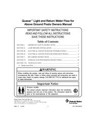
<strong>Valve</strong> & Filter Connection <strong>Guide</strong><br />
PENTAIR<br />
STA-RITE<br />
XF FILTERS<br />
P/N 263081<br />
P/N 262508 P/N 262512<br />
Filter Inlet- BOTTOM<br />
Filter P/N<br />
<strong>Pentair</strong> Filters<br />
Filter P/N<br />
Sta-Rite Filters<br />
Filter P/N<br />
XF Filters<br />
Filter P/N<br />
XF Filters<br />
180006 FNS Plus FNSP24<br />
180007 FNS Plus FNSP36<br />
S7D75<br />
S8D110<br />
System 3 DE Filter<br />
System 3 DE Filter<br />
188626 XF Q-60 DE<br />
188627 XF Q-80 DE<br />
188618 XF F-36 DE<br />
188619 XF F-48 DE<br />
180008 FNS Plus FNSP48<br />
S7S50<br />
System 3 S<strong>and</strong> Filter<br />
188613 XF Q-100 DE<br />
188620 XF F-60 DE<br />
180009 FNS Plus FNSP60<br />
S8S70<br />
System 3 S<strong>and</strong> Filter<br />
188616 XF Q-120 DE<br />
188621 XF F-72 DE<br />
PENTAIR<br />
STA-RITE<br />
P/N 263080 P/N 262507<br />
Filter Inlet - TOP<br />
Filter P/N<br />
<strong>Pentair</strong> Filters<br />
Filter P/N<br />
<strong>Pentair</strong> Filters<br />
Filter P/N<br />
Sta-Rite Filters<br />
188592 Quad DE 60<br />
188593 Quad DE 80<br />
140264 TR 60 S<strong>and</strong><br />
140210 TR 100 S<strong>and</strong><br />
PLDE 36<br />
PLDE48<br />
System 2 Mod DE<br />
System 2 Mod DE<br />
188594 Quad DE 100<br />
140243 TR 140 S<strong>and</strong><br />
S7MD60<br />
System 3 Mod DE<br />
140212 TR 60 S<strong>and</strong><br />
140236 TR 40 S<strong>and</strong><br />
140335 TR 100 HD<br />
140315 TR 100C S<strong>and</strong><br />
S7MD72<br />
System 3 Mod DE<br />
140249 TR 50 S<strong>and</strong><br />
140316 TR 140C S<strong>and</strong><br />
<strong>FullFloXF</strong> <strong>Backwash</strong> <strong>Valve</strong> <strong>Installation</strong> <strong>and</strong> User’s <strong>Guide</strong>
SAVE THESE INSTRUCTIONS<br />
© 2012 <strong>Pentair</strong> Water Pool <strong>and</strong> Spa, Inc. All rights reserved.<br />
1620 Hawkins Ave., Sanford, NC 27330 • (919) 566-8000<br />
10951 West Los Angeles Ave., Moorpark, CA 93021 • (805) 553-5000<br />
This document is subject to change without notice.<br />
<strong>FullFloXF</strong> , Sta-Rite ® , <strong>and</strong> <strong>Pentair</strong> Water Pool <strong>and</strong> Spa ® are trademarks <strong>and</strong>/or registered trademarks of <strong>Pentair</strong> Water Pool <strong>and</strong> Spa, Inc.<br />
<strong>and</strong>/or its affiliated companies in the United States <strong>and</strong>/or other countries. Weld-On ® is a registered trademark of IPS Corporation <strong>and</strong><br />
Dow Corning ® is a registered trademark of Dow Corning Corporation. Unless noted, names <strong>and</strong> br<strong>and</strong>s of others that may be used in this<br />
document are not used to indicate an affiliation or endorsement between the proprietors of these names <strong>and</strong> br<strong>and</strong>s <strong>and</strong> <strong>Pentair</strong> Water<br />
Pool <strong>and</strong> Spa, Inc. Those names <strong>and</strong> br<strong>and</strong>s may be the trademarks or registered trademarks of those parties or others.<br />
*270505*<br />
P/N 270505 Rev. B 4/19/12