IntelliChlor Electronic Chlorine Generator COMSYS-4 - Pentair
IntelliChlor Electronic Chlorine Generator COMSYS-4 - Pentair
IntelliChlor Electronic Chlorine Generator COMSYS-4 - Pentair

Create successful ePaper yourself
Turn your PDF publications into a flip-book with our unique Google optimized e-Paper software.
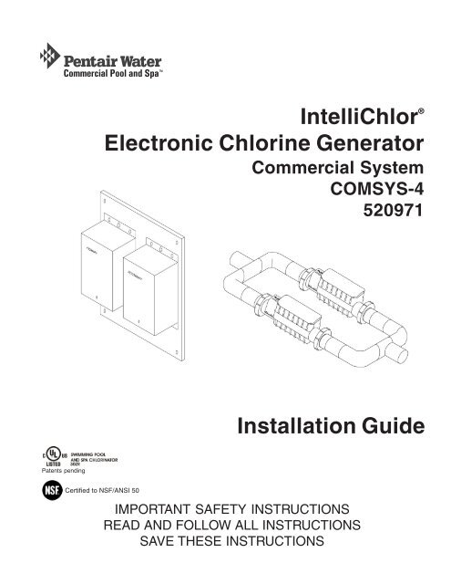
<strong>IntelliChlor</strong> ®<br />
<strong>Electronic</strong> <strong>Chlorine</strong> <strong>Generator</strong><br />
Commercial System<br />
<strong>COMSYS</strong>-4<br />
520971<br />
Installation Guide<br />
Patents pending<br />
Certified to NSF/ANSI 50<br />
IMPORTANT SAFETY INSTRUCTIONS<br />
READ AND FOLLOW ALL INSTRUCTIONS<br />
SAVE THESE INSTRUCTIONS
© 2009 <strong>Pentair</strong> Water Pool and Spa, Inc. All rights reserved<br />
This document is subject to change without notice<br />
1620 Hawkins Ave., Sanford, NC 27330 (919) 566-8000<br />
10951 West Los Angeles Ave., Moorpark, CA 93021 • (800) 831-7133 • (805) 553-5000<br />
<strong>IntelliChlor</strong> ® and <strong>Pentair</strong> Water Commercial Pool and Spa are trademarks and/or registered trademarks of <strong>Pentair</strong><br />
Water Pool and Spa, Inc. and/or its affiliated companies in the United States and/or other countries. Unless noted,<br />
names and brands of others that may be used in this document are not used to indicate an affiliation or<br />
endorsement between the proprietors of these names and brands and <strong>Pentair</strong> Water Pool and Spa, Inc. Those<br />
names and brands may be the trademarks or registered trademarks of those parties or others.<br />
P/N 520981 Rev A - 1/24/09
i<br />
Contents<br />
IMPORTANT SAFETY PRECAUTIONS ....................................................................................................... ii<br />
Installation Steps Summary........................................................................................................................ iii<br />
Technical Support ....................................................................................................................................... iii<br />
<strong>IntelliChlor</strong> ® <strong>Electronic</strong> <strong>Chlorine</strong> <strong>Generator</strong> <strong>COMSYS</strong>-4 Overview.................................. 1<br />
Features .......................................................................................................................... 1<br />
Preparing the Site ........................................................................................................... 1<br />
Installation....................................................................................................................... 2<br />
Kit Contents .................................................................................................................... 2<br />
Required Tools ............................................................................................................ 2<br />
Mount Primary and Secondary Power Center To Wall ..................................................... 3<br />
Connect AC Power Wires and ORP Sensor Wires .......................................................... 3<br />
Assemble the Manifold.................................................................................................... 4<br />
Connect the <strong>IntelliChlor</strong> Cells ......................................................................................... 5<br />
Power Centers ................................................................................................................ 6<br />
Power Up the system ...................................................................................................... 7<br />
Operation ........................................................................................................................ 7<br />
Troubleshooting .............................................................................................................. 8<br />
<strong>IntelliChlor</strong> <strong>Electronic</strong> <strong>Chlorine</strong> <strong>Generator</strong> <strong>COMSYS</strong>-4 Installation Guide
ii<br />
IMPORTANT SAFETY PRECAUTIONS<br />
SAVE THESE INSTRUCTIONS<br />
Important Notice: Attention Installer: This manual contains important information about the<br />
installation, operation and safe use of this product. This information should be given to the owner and/or<br />
operator of this equipment. When installing and using this electrical equipment, basic safety precautions should<br />
always be followed, including the following:<br />
WARNING: IMPORTANT SAFETY INSTRUCTIONS PERTAINING TO A RISK OF FIRE,<br />
ELECTRIC SHOCK, OR INJURY TO PERSONS. READ AND FOLLOW ALL<br />
INSTRUCTIONS.<br />
Before installing this product, read and follow all warning notices and instructions which are<br />
included. Failure to follow safety warnings and instructions can result in severe injury, death,<br />
or property damage. Call (800) 831-7133 for additional free copies of these instructions.<br />
WARNING: To reduce the risk of injury, do not permit children to use this product.<br />
WARNING: CHLORINE GAS BUILDUP CAN OCCUR WITH IMPROPER WIRING: To reduce the risk of<br />
personal injury the <strong>IntelliChlor</strong> ® <strong>Electronic</strong> <strong>Chlorine</strong> <strong>Generator</strong> (IECG) Power Supply must be installed on and<br />
wired to the load side of the time clock, electronically controlled switch, or relay load side, so that it will<br />
receive power only when the pool pump is on. Otherwise, dangerous chlorine gas buildup can occur. The IECG<br />
should never be energized when the pool pump is OFF and water is not flowing through the unit.<br />
WARNING: To reduce the risk of injury, service should only be personnel by a qualified pool<br />
service professional.<br />
WARNING: Never operate the <strong>IntelliChlor</strong> <strong>Electronic</strong> <strong>Chlorine</strong> <strong>Generator</strong> (IECG) without proper flow or<br />
water circulation. A build-up of flammable gases will result in hazardous conditions.<br />
CAUTION - <strong>IntelliChlor</strong> <strong>Electronic</strong> <strong>Chlorine</strong> <strong>Generator</strong> (IECG) is for use with permanently-installed pools<br />
and may also be used with hot tubs and spas if so marked. Do not use with storable pools. A permanentlyinstalled<br />
pool is constructed in or on the ground or in a building such that it cannot be readily disassembled for<br />
storage. A storable pool is constructed so that it is capable of being readily disassembled for storage and<br />
reassembled to its original integrity.<br />
CAUTION - The CIC60 Power Center must be interconnected with pool pump motor power source. This<br />
ensures the IECG and pool pump will switch on and off together.<br />
WARNING - The CIC60 Power Center is only intended for use with the CIC60 cell, DO NOT PLUG ANY<br />
OTHER INTELLICHLOR CELL INTO THIS POWER CENTER, SEVERE DAMAGE WILL RESULT.<br />
<strong>IntelliChlor</strong> <strong>Electronic</strong> <strong>Chlorine</strong> <strong>Generator</strong> <strong>COMSYS</strong>-4 Installation Guide
iii<br />
IMPORTANT SAFETY PRECAUTIONS<br />
SAVE THESE INSTRUCTIONS<br />
WARNING: When mixing acid with water, ALWAYS ADD ACID TO WATER. NEVER ADD<br />
WATER TO ACID.<br />
CAUTION - Use of chemicals other than those recommended may be hazardous. Even proper use of the<br />
recommended chemicals can be hazardous. Follow the Chemical Manufacturer’s Instructions.<br />
CAUTION - To reduce the risk of electric shock, install <strong>IntelliChlor</strong> <strong>Electronic</strong> <strong>Chlorine</strong> <strong>Generator</strong> (IECG)<br />
a minimum of five (5) feet away from the inside wall of the pool.<br />
CAUTION - Install the IECG a minimum of three (3) feet away from the heater outlet.<br />
CAUTION - It is recommended to install a <strong>Pentair</strong> two (3) inch CHECK VALVE (P/N 263060) between<br />
the input side of the IECG and the main heater output pipe.<br />
CAUTION - A solid copper, bonding conductor not smaller than No. 8 AWG (8.4 mm) should be connected<br />
to all metal parts of the swimming pool, spa, or hot tub structure and to all electrical equipment, metal conduit,<br />
and metal piping within five (5) feet (1.5 m) of the inside walls of a swimming pool, spa, or hot tub, when the unit<br />
is installed within five (5) feet of the inside walls of the swimming pool, spa, or hot tub.<br />
Canada - Industry Canada (IC) - This device complies with RSS210 of Industry Canada. (1999)<br />
FCC Standard - 47 CFR Part 15, Subpart C (Section 15.247). This version is limited to chapter 1 to chapter 11<br />
by specified firmware controlled in the U.S.A.<br />
Federal Communications Commission (FCC) - This device complies with Part 15 of the FCC Rules.<br />
Operation is subject to the following two conditions: (1) this device may not cause interference, and (2) this<br />
device must accept any interference, including interference that may cause undesired operation of the device.<br />
Interference Statement - This equipment has been tested and found to comply with the limits for a Class B<br />
digital device, pursuant to Part 15 of the FCC Rules. These limits are designed to provide reasonable protection<br />
against harmful interference in a residential installation. This equipment generates, uses and can radiate radio<br />
frequency energy and, if not installed and used in accordance with the instructions, may cause harmful<br />
interference to radio communications. However, there is no guarantee that interference will not occur in a<br />
particular installation. If this equipment does cause harmful interference to radio or television reception, which<br />
can be determined by turning the equipment off and on, the user is encouraged to try to correct the interference<br />
by one or more of the following measures:<br />
• Reorient or relocate the receiving antenna.<br />
• Increase the separation between the equipment and receiver.<br />
• Connect the equipment into an outlet on a circuit different from that to which the receiver is connected.<br />
• Consult the dealer or an experienced radio/TV technician for help.<br />
Note: Modifications not expressly approved by the party responsible for FCC compliance could void the user’s<br />
authority to operate the device.<br />
<strong>IntelliChlor</strong> <strong>Electronic</strong> <strong>Chlorine</strong> <strong>Generator</strong> <strong>COMSYS</strong>-4 Installation Guide
iv<br />
Technical Support<br />
Web sites<br />
Sanford, North Carolina (8 A.M. to 5 P.M. Eastern Time)<br />
Moorpark, California (8 A.M. to 5 P.M. Pacific Time)<br />
Phone: (800) 831-7133<br />
Fax: (800) 284-4151<br />
visit www.pentairpool.com and www.staritepool.com<br />
<strong>IntelliChlor</strong> <strong>Electronic</strong> <strong>Chlorine</strong> <strong>Generator</strong> <strong>COMSYS</strong>-4 Installation Guide
1<br />
<strong>IntelliChlor</strong> ® <strong>Electronic</strong> <strong>Chlorine</strong> <strong>Generator</strong> <strong>COMSYS</strong>-4 Overview<br />
The <strong>IntelliChlor</strong> <strong>COMSYS</strong>-4 commercial system consists of two <strong>IntelliChlor</strong> cells (primary and secondary) and<br />
two power centers (primary and secondary).<br />
Each cell can produce up to 2.00 lbs of pure chlorine per 24 hours of operation. These cells can sanitize either<br />
a pool or spa, or combination of both. A commercial system requires an external ORP panel and sensor to<br />
produce chlorine upon demand as needed. The ORP system is sold separately.<br />
Features<br />
• Each cell draws approximately 220 Watts.<br />
• Dry contact wires on primary power center connect to chlorine controller panel (ORP system).<br />
Closing these wires sets the cells on at 100% producing chlorine. Opening these two wires sets the<br />
cells off at 0%, and no chlorine will be produced.<br />
• Each cell produces 2.00 pounds of chlorine per 24 hours.<br />
• Comsys-4 produces four pounds of chlorine per day.<br />
• The ORP system (not provided) is a separate device that monitors the available chlorine in the water<br />
and, when needed, calls for chlorine to be produced by closing a dry contact output. An ORP system<br />
consists of a panel, usually with an LCD display, that has the ORP sensor in the water.<br />
Preparing the Site<br />
1. Add salt to the water until it measures 3500 ppm. Use an electronic tester to measure salt, such as<br />
the Extech EC400. DO NOT USE SALT TEST STRIPS AS THEY TEND TO BE INACCURATE.<br />
Allow the salt to mix for 24 hours before using the <strong>IntelliChlor</strong> system.<br />
2. Locate a clear spot on a wall, within 15 feet of the <strong>IntelliChlor</strong> manifold.<br />
3. Locate a clear spot on the return line where the <strong>IntelliChlor</strong> manifold will be mounted. Be sure that<br />
the user can readily see the lights and press buttons if needed.<br />
4. Be sure 110VAC or 220VAC is available and on its own circuit breaker, to power the <strong>IntelliChlor</strong><br />
power centers. This separate breaker will make it easier to service the <strong>IntelliChlor</strong>.<br />
5. Be sure 110VAC or 220VAC is provided to the power center bank in a conduit, for maximum safety<br />
and NEC compliance.<br />
<strong>IntelliChlor</strong> <strong>Electronic</strong> <strong>Chlorine</strong> <strong>Generator</strong> <strong>COMSYS</strong>-4 Installation Guide
2<br />
Installation<br />
Before installing the <strong>IntelliChlor</strong> CIC60 system, please read all SAFEY PRECAUTIONS below.<br />
Kit Contents<br />
- One Primary Power Center<br />
- One Secondary Power Center<br />
- One Primary CIC60P cell<br />
- One Secondary CIC60S cell<br />
- Installation Guide (this manual)<br />
Required Tools<br />
- Medium phillips or flathead screwdriver (and four screws)<br />
- Electric drill and 1/4" masonry drill bit. (To mount Power Center Bank)<br />
SAFETY PRECAUTIONS - PLEASE READ BEFORE PROCEEDING<br />
IMPORTANT SAFETY PRECAUTIONS. PLEASE READ THE FOLLOWING:<br />
Read all the safety precautions in this manual before attempting any electrical wiring. Be<br />
sure to read and follow all safety Instructions on page ii. Wiring should only be performed<br />
by a qualified professional. When using electrical products, basic precautions should<br />
always be followed, including the following:<br />
RISK OF ELECTRIC SHOCK, WHICH CAN RESULT IN SERIOUS INJURY OR DEATH. Before<br />
attempting installation of service, ensure that all power to the circuit supplying power to the<br />
system is disconnected/switched off at the circuit breaker. The Power Center must be<br />
interconnected with pool pump motor power source. This insures the <strong>IntelliChlor</strong> chlorinator and<br />
pool pump will switch on and off together.<br />
• Grounding (earth bonding) is required. The unit should be installed by a qualified service person<br />
and grounded.<br />
CAUTION - Install the <strong>IntelliChlor</strong> cell a minimum of two (2) feet from the heater outlet.<br />
• Allow ample access to the <strong>IntelliChlor</strong> control panel buttons and the <strong>IntelliChlor</strong> Power Center.<br />
• Pipe couplings: Schedule 80, maximum pressure 150 psi at 70° F.<br />
• Operate unit with minimum flow of 25 gpm. For high flow applications, use a bypass loop.<br />
<strong>IntelliChlor</strong> <strong>Electronic</strong> <strong>Chlorine</strong> <strong>Generator</strong> <strong>COMSYS</strong>-4 Installation Guide
3<br />
Mount Primary and Secondary Power Center To Wall<br />
1. Locate a wall near the pool equipment area within 15 feet of the<br />
<strong>IntelliChlor</strong> cells. Position the primary and secondary power center<br />
at eye level. Mount and secure the power center bank to the wall<br />
using four (4) screws (not provided in kit). Note: The power<br />
centers are pre-wired to each other.<br />
2. Remove the cover retaining screw and remove the cover from the<br />
PRIMARY power center.<br />
Mount power centers to wall<br />
using four (4) screws<br />
Connect AC Power Wires and ORP Sensor Wires<br />
1. Provide 208-260VAC power to the PRIMARY POWER CENTER This power should be on its<br />
own breaker for future servicing. A (knock-out) opening is provided on the bottom of the power<br />
center for a conduit.<br />
Note: For 110VAC operations, each power center will need to be re-configured. A 110VAC<br />
wiring diagram is provided on the inside of each the power center covers.<br />
2. Splice the incoming AC power wires onto the two wires labeled WIRED FOR 220V. Do not<br />
apply AC power yet.<br />
3. Connect the two (2) twisted wires labeled ORP SENSOR to the ORP chlorine controller panel<br />
(AcuTrol, etc). Carefully place the connection inside of power center.<br />
4. Replace the cover. Secure it using the retaining screw.<br />
Connect these<br />
wires to AC<br />
power source<br />
Connect these<br />
wires to ORP<br />
PRIMARY<br />
SECONDARY<br />
<strong>IntelliChlor</strong> <strong>Electronic</strong> <strong>Chlorine</strong> <strong>Generator</strong> <strong>COMSYS</strong>-4 Installation Guide
4<br />
Assemble the Manifold<br />
1. Place an o-ring into groove on union coupling.<br />
2. Place each cell on the manifold and tighten coupling nut securely. Be sure the o-ring stays in place.<br />
Note: Cells labeled PRIMARY and SECONDARY can be placed anywhere in the<br />
manifold, they do not need to be in a specific location.<br />
3. Glue the manifold into the system plumbing at desired location, either horizontal or vertical. Make<br />
sure the cells are readable and the buttons can be pressed if needed.<br />
CAUTION: Do not install upside down!<br />
4. Verify water flow direction See the FLOW arrow located on the <strong>IntelliChlor</strong> cell near the input<br />
coupling.<br />
Union coupling nut<br />
O-ring<br />
Manifold<br />
Coupling<br />
WATER FLOW<br />
System pipes<br />
Coupling<br />
<strong>IntelliChlor</strong> cell<br />
(Primary or<br />
Secondary)<br />
Manifold<br />
<strong>IntelliChlor</strong> cell<br />
(Primary or<br />
Secondary)<br />
System pipes<br />
<strong>IntelliChlor</strong> <strong>Electronic</strong> <strong>Chlorine</strong> <strong>Generator</strong> <strong>COMSYS</strong>-4 Installation Guide
5<br />
Connect the <strong>IntelliChlor</strong> Cells<br />
1. Connect the cell power connector, labeled PRIMARY (CIC60P), into the receptacle on the<br />
bottom of the power center labeled PRIMARY. While holding the connector on the receptacle,<br />
turn it slowly until the plug pins are inserted into the receptacle, then twist the to lock in place.<br />
2. Plug the SECONDARY cell power connector into the power center labeled SECONDARY using<br />
same method as described in step 1.<br />
Primary (CIC60P) connector<br />
Secondary connector<br />
Primary (CIC60P)<br />
power center receptacle<br />
Secondary power<br />
center receptacle<br />
PRIMARY<br />
SECONDARY<br />
<strong>IntelliChlor</strong> <strong>Electronic</strong> <strong>Chlorine</strong> <strong>Generator</strong> <strong>COMSYS</strong>-4 Installation Guide
6<br />
Power Centers<br />
The PRIMARY and SECONDARY power centers are pre-wired as shown below.<br />
PRIMARY<br />
SECONDARY<br />
Power Center connection wire<br />
Power Centers (Front View)<br />
<strong>IntelliChlor</strong> <strong>Electronic</strong> <strong>Chlorine</strong> <strong>Generator</strong> <strong>COMSYS</strong>-4 Installation Guide
7<br />
Power Up the system<br />
1. Switch the AC circuit breaker to ON to apply AC power to the system.<br />
2. After the system is powered up for one minute, if any SECONDARY cell shows a red PWR light,<br />
the communications to that cell is not connected.<br />
Open the power center covers and verify the two green and yellow wires on each terminal block<br />
are connected and in the same order. Verify these connections from each SECONDARY power<br />
center to the PRIMARY power center (see page 6).<br />
3. Apply water flow to the cell manifold. When water flow is present, each cell's FLOW light will go<br />
from red (no flow) to green (flow).<br />
4. The GOOD, CHECK SALT and LOW salt lights on each cell will scroll back and forth for two<br />
minutes before checking the salt level. If water flow is not present, then restored, this two minutes<br />
will start over. Note: THE SALT LEVEL CAN NOT BE CHECKED WHEN THE FLOW<br />
LIGHT IS RED.<br />
5. After two minutes, the salt level will be read and displayed on both cells.<br />
Operation<br />
When the ORP system requests chlorine, it closes the dry-contact output that is connected to the ORP<br />
SENSOR wires, and causes each cell to light their 100% light. The CELL light will turn on and chlorine will<br />
be produced. If the ORP system is not requesting chlorine (ORP SENSOR wires open), all lights in the<br />
SANITIZER OUTPUT section will be off, no chlorine is produced.<br />
<strong>Chlorine</strong> will be produced only when:<br />
• SANITIZER OUTPUT 100% light is on<br />
• CELL is green and not flashing<br />
• FLOW light is green<br />
• Salt is FLASHING GOOD, GOOD, or CHECK SALT<br />
• PWR light is green<br />
Note: Verify each cell has a green FLOW light, to show that adequate water is flowing through the cell.<br />
• After power up, both cells will scroll the salt lights LOW, CHECK SALT and GOOD for 2 minutes<br />
while waiting to check salt. If FLOW is red, these lights will scroll indefinitely.<br />
• After 2 minutes of green FLOW, the salt will be read and both cells will now display the same salt<br />
color.<br />
• The cells will produce chlorine whenever the ORP controller calls for chlorine.<br />
• Set the ORP controller to the desired chlorine levels and cutoff (not part of the <strong>IntelliChlor</strong> system).<br />
• If the CELL light is flashing, the cell has become dirty and requires acid cleaning. Turn off the circuit<br />
breaker to the power centers, disable water flow through the manifold (either an external valve or<br />
turn off the filter pump), and remove the cell. Check the cell and acid clean if necessary.<br />
<strong>IntelliChlor</strong> <strong>Electronic</strong> <strong>Chlorine</strong> <strong>Generator</strong> <strong>COMSYS</strong>-4 Installation Guide
8<br />
Troubleshooting<br />
The <strong>IntelliChlor</strong> 100% light does not come on when the chlorine controller calls for chlorine<br />
1. Verify the ORP controller is opening and closing the dry-contact output.<br />
2. Remove the ORP SENSOR wires connection from the PRIMARY power center and the ORP<br />
controller. Manually tie the ORP SENSOR wires together. This will turn on the cells at 100%. If<br />
the 100% lights do not come on for each cell or only one cell, verify the communication wires are<br />
connected, shown in POWER UP THE SYSTEM, step 3, page 7.<br />
3. If the PWR light is red, the communications are lost, refer to section 5 POWER UP THE SYSTEM,<br />
step 3. If the cable connection is good, replace the master board in the PRIMARY power center.<br />
The <strong>IntelliChlor</strong> 100% light stays on after the chlorine controller says to stop<br />
1. Verify the communication wires are connected, as shown in section 5, POWER UP THE SYSTEM,<br />
step 3.<br />
2. Verify the ORP SENSOR wires are not shorted together in the power center.<br />
3. Verify the ORP controller dry contact output is opening and closing by using an ohmmeter. Manually<br />
set this output open and closed using the controller menu system.<br />
The CHECK SALT light is on<br />
More salt needs to be added to the water.<br />
1. Add salt to the water and bring up to 3500ppm. Allow it to mix for 24 hours.<br />
2. The salt level will be automatically checked every 8 hours by the cells and displayed.<br />
The LOW salt light is on<br />
Not enough salt is in the water to produce chlorine, cell is OFF.<br />
1. Add salt to the water and bring up to 3500ppm. Allow it to mix for 24 hours.<br />
2. The salt level will be checked every 8 hours by the cells and displayed.<br />
Not enough chlorine is produced<br />
1. Ensure the ORP sensor probe on the chlorine controller unit is clean and working.<br />
2. Verify the <strong>IntelliChlor</strong> cells do not have a flashing CELL light. If so, remove the cell and acid clean.<br />
3. Verify no debris is in the cells. Remove if present.<br />
4. Verify the FLOW light is green, for adequate water flow.<br />
5. Verify the salt level lights are displaying either green GOOD or yellow CHECK SALT. If displaying<br />
yellow CHECK SALT, add salt to the water, and allow to mix for 24 hours.<br />
6. Verify the ORP controller sets the cells to 100% SANITIZER OUTPUT or 0%, by manually<br />
controlling this output relay (done in the ORP controller, not the <strong>IntelliChlor</strong>) or by disconnecting the<br />
ORP SENSOR wires from the power center and manually opening and closing the wires.<br />
7. Verify the ORP probe is clean.<br />
8. Verify the filter pump is not being turned off by a timer.<br />
<strong>IntelliChlor</strong> <strong>Electronic</strong> <strong>Chlorine</strong> <strong>Generator</strong> <strong>COMSYS</strong>-4 Installation Guide
9<br />
The PWR light is red.<br />
1. Communication has been lost between the power centers and cells. Verify the communication<br />
connection. See “POWER UP THE SYSTEM” step 3, page 7.<br />
2. If the communications are connected, replace the master board in the PRIMARY power center.<br />
The cell is not powered up<br />
1. Check fuse, replace if open.<br />
2. Check if cell connector is plugged and twist-locked all the way in.<br />
Fuse is blown<br />
1. Replace with 12 amp ceramic fuse. DO NOT USE 10AMP glass (a common fuse), it is not reliable<br />
and might fail later. If the fuse blows again, replace the cell.<br />
2. Verify the Power center is not wired for 110VAC and has 220VAC applied to it. THIS IS NOT<br />
COVERED BY THE WARRANTY.<br />
<strong>IntelliChlor</strong> <strong>Electronic</strong> <strong>Chlorine</strong> <strong>Generator</strong> <strong>COMSYS</strong>-4 Installation Guide
10<br />
Blank Page<br />
<strong>IntelliChlor</strong> <strong>Electronic</strong> <strong>Chlorine</strong> <strong>Generator</strong> <strong>COMSYS</strong>-4 Installation Guide
LIMITED WARRANTY<br />
<strong>Pentair</strong> Water Pool and Spa, Inc. ("<strong>Pentair</strong> Water") warrants the <strong>IntelliChlor</strong> ® <strong>Electronic</strong> <strong>Chlorine</strong> <strong>Generator</strong> (IECG)<br />
as follows:<br />
IECG Limited Warranty: <strong>Pentair</strong> Water warrants the IECG to be free from defects in material and/or<br />
workmanship for a period of one (1) year (parts only) from the original date of installation.<br />
IECG Power Center Limited Warranty: <strong>Pentair</strong> Water warrants the IECG Power Center to be free from defects<br />
in material and/or workmanship for a period of one (1) (parts only) from the original date of installation.<br />
Exceptions that shall result in <strong>Pentair</strong>’s denial of a warranty claim:<br />
1. Damage caused by careless handling, improper repackaging, or shipping.<br />
2. Damage due to misapplication, misuse, abuse or failure to operate equipment as specified in the IECG<br />
Installation and User’s Guide.<br />
3. Damage caused by failure to install products as specified in the IECG Installation and User’s Guide.<br />
4. Damage due to unauthorized product modifications or alterations, or failure to use <strong>Pentair</strong> Water<br />
original replacement parts.<br />
5. Damage caused by negligence, or failure to properly maintain products as specified in the IECG<br />
Installation and User’s Guide.<br />
6. Damage caused by failure to maintain water chemistry in conformity with the standards set forth in the<br />
IECG Installation and User’s Guide.<br />
7. Damage caused by water scaling, freezing or any conditions causing inadequate water circulation.<br />
8. Accidental damage, fire, acts of God, or other circumstances outside the control of <strong>Pentair</strong> Water.<br />
• This warranty extends to the original retail owner (Customer) only, beginning on the date of installation<br />
and is not enforceable by any other party. Proof of purchase and/or date of installation will be required<br />
for all warranty claims. Customer agrees to pay all shipping charges to <strong>Pentair</strong> Water.<br />
• Warranties by others: Some products incorporate components manufactured by other manufacturers.<br />
Some of these provide warranties in addition to the warranty provided herein. In all such cases a copy<br />
of that warranty will be provided with the product. To the extent protection provided under any such<br />
third party warranty exceeds the Limited Warranty provided herein, the Customer must look only to<br />
that other manufacturer for the additional warranty protection.<br />
Warranty Obligations of <strong>Pentair</strong> Water: Should a defect in workmanship and/or material in any item covered<br />
by this warranty become evident during the term of the warranty, then upon the Customer following the<br />
procedures set forth below, <strong>Pentair</strong> Water will, at its option, repair or replace such item or part at its own cost<br />
and expense. <strong>Pentair</strong> Water’s maximum obligation under this warranty is limited to the repair and replacement of<br />
the IECG. <strong>Pentair</strong> Water disclaims all other expressed or implied warranty obligations.<br />
<strong>Pentair</strong> Water is not, however, responsible under this warranty for any cost of shipping or transportation of the<br />
equipment or parts thereof to or from <strong>Pentair</strong> Water’s Technical Service Department. Also, <strong>Pentair</strong> Water is not<br />
liable for any loss of time, inconvenience, incidental expenses such as telephone calls, labor or material<br />
charges incurred in connection with the removal or replacement of the equipment, or any other incidental or<br />
consequential damages, including but not limited to damage to pool equipment or any surface in or around the<br />
pool in which the IECG is installed.<br />
PLEASE NOTE: Some states do not allow the exclusion or limitation of incidental, or consequential damages,<br />
so the above limitation or exclusion may not apply to you.<br />
No Other Warranties: TO THE MAXIMUM EXTENT PERMITTED BY APPLICABLE LAW, PENTAIR WATER<br />
DISCLAIMS ALL OTHER WARRANTIES, WHETHER EXPRESS OR IMPLIED, INCLUDING, BUT NOT<br />
LIMITED TO THE IMPLIED WARRANTIES OF MERCHANTABILITY AND FITNESS FOR A PARTICULAR<br />
PURPOSE.<br />
Continued on back page.
LIMITED WARRANTY (Continued)<br />
Procedure for Obtaining Performance: In order to obtain the benefits of this warranty, the Customer who<br />
made the original retail purchase must contact the <strong>Pentair</strong> Water Technical Service Department upon discovery<br />
of the defect, but in no event later than the expiration date of the warranty period provided in this warranty.<br />
Upon receipt of this communication, <strong>Pentair</strong> Water will promptly notify the Customer of the address to which the<br />
defective item may be shipped. The Customer shall then ship the item, freight prepaid, to the address<br />
indicated, together with a "RETURN GOODS AUTHORIZATION" form obtained from <strong>Pentair</strong> Water’s Technical<br />
Service and a brief description of the problems encountered. Unauthorized returns will not be accepted. Freight<br />
must be prepaid by customer.<br />
Warranties or Representations by Others: No dealer or other third party entity has any authority to make any<br />
warranties or representations concerning <strong>Pentair</strong> Water or its products. Accordingly, <strong>Pentair</strong> Water is not<br />
responsible for any such warranties or representations.<br />
Other Rights: This warranty gives you specific legal rights and you may also have other rights, which vary from<br />
state to state. This warranty supersedes all previous publications.<br />
PENTAIR WATER POOL AND SPA, INC.<br />
1620 Hawkins Ave. Sanford, NC 27330 - 10951 W. Los Angeles Ave. Moorpark, CA 93021 - Phone 800-831-<br />
7133 - Fax 800-284-4151<br />
WARNING: Salt is an inherently corrosive material. While the levels of salt required for proper operation<br />
of the <strong>IntelliChlor</strong> <strong>Electronic</strong> <strong>Chlorine</strong> <strong>Generator</strong> are relatively low when compared to sea water and other salt<br />
solutions, placing any amount of salt in your pool increases the likelihood of corrosion or other deterioration of<br />
pool equipment and any surfaces used in and around your pool. Metal parts and certain natural and man-made<br />
surfaces are particularly susceptible to corrosion and deterioration when used in and around salt water pools.<br />
<strong>Pentair</strong> Water Pool and Spa does not represent or otherwise guarantee that the proper use of the <strong>IntelliChlor</strong><br />
<strong>Electronic</strong> <strong>Chlorine</strong> <strong>Generator</strong> will prevent corrosion or other deterioration of pool equipment and any surfaces<br />
used in and around your pool. Consult your experienced pool professional, who should be able to advise you on<br />
the proper material selection, installation techniques for those materials, and the proper use, care and<br />
maintenance of those materials for your specific pool type and location in order to minimize the corrosion and<br />
deterioration that is inherent in and around salt water pools.<br />
*520981*<br />
P/N 520981 - Rev A