Intelliflo VF Installation / Owners Manual - Pool Center
Intelliflo VF Installation / Owners Manual - Pool Center
Intelliflo VF Installation / Owners Manual - Pool Center

Create successful ePaper yourself
Turn your PDF publications into a flip-book with our unique Google optimized e-Paper software.
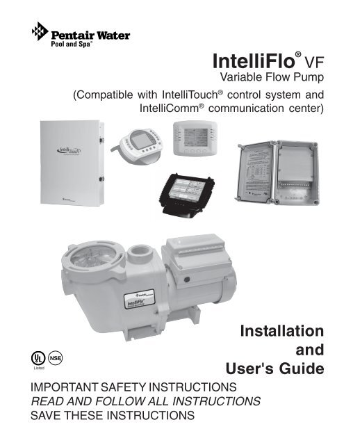
IntelliFlo ® <strong>VF</strong><br />
Variable Flow Pump<br />
(Compatible with IntelliTouch ® control system and<br />
IntelliComm ® communication center)<br />
Listed<br />
IMPORTANT SAFETY INSTRUCTIONS<br />
READ AND FOLLOW ALL INSTRUCTIONS<br />
SAVE THESE INSTRUCTIONS<br />
<strong>Installation</strong><br />
and<br />
User's Guide
Technical Support<br />
Sanford, North Carolina (8 A.M. to 5 P.M. ET)<br />
Moorpark, California (8 A.M. to 5 P.M. PT)<br />
Phone: (800) 831-7133<br />
Fax: (800) 284-4151<br />
Web sites: www.pentairpool.com and www.staritepool.com<br />
Protected by U.S. Patents Pending<br />
© 2009 Pentair Water <strong>Pool</strong> and Spa, Inc. All rights reserved<br />
This document is subject to change without notice.<br />
1620 Hawkins Ave., Sanford, NC 27330 • (919) 566-8000<br />
10951 West Los Angeles Ave., Moorpark, CA 93021 • (805) 553-5000<br />
Trademarks and disclaimers: IntelliFlo ® , IntelliTouch ® , EasyTouch ® , SunTouch ® , IntelliComm ® and Pentair Water <strong>Pool</strong><br />
and Spa ® are trademarks and/or registered trademarks of Pentair Water <strong>Pool</strong> and Spa, Inc. and/or its affiliated<br />
companies in the United States and/or other counties. Teflon ® is a registered trademark of E.I. Du Pont De Nemours and<br />
Company Corporation. Unless noted, names and brands of others that may be used in this document are not used to<br />
indicate an affiliation or endorsement between the proprietors of these names and brands and Pentair Water <strong>Pool</strong> and<br />
Spa, Inc. Those names and brands may be the trademarks or registered trademarks of those parties or others.<br />
P/N 350075 Rev D - 7-14-09
i<br />
Contents<br />
Important Safety Precautions ........................................................................................... iii<br />
Section 1: Introduction ...................................................................................................... 1<br />
IntelliFlo Overview................................................................................................................. 1<br />
IntelliFlo Features...................................................................................................... 2<br />
IntelliFlo Motor Assembly .......................................................................................... 2<br />
IntelliFlo Motor Features ............................................................................................ 3<br />
IntelliFlo Drive Assembly and Control Panel ............................................................. 4<br />
Operator Control Panel Features ............................................................................. 4<br />
Section 2: Operator Control Panel................................................................................... 5<br />
IntelliFlo Operator Control Panel ........................................................................................... 5<br />
Controls and LEDs ................................................................................................... 5<br />
Navigating the Menu Structure .............................................................................................. 7<br />
Section 3: Operating IntelliFlo .......................................................................................... 9<br />
Metering the System.............................................................................................................9<br />
<strong>Manual</strong> Mode ........................................................................................................................ 9<br />
IntelliFlo Control Panel Menu ............................................................................................... 11<br />
Menu Structure .................................................................................................................... 12<br />
<strong>Pool</strong> Data Mode ....................................................................................................... 13<br />
Priming Mode ........................................................................................................... 14<br />
Priming Menu ........................................................................................................ 14<br />
Filter Mode ............................................................................................................... 16<br />
Filter Menu ............................................................................................................ 16<br />
Programming Cycles Per Day .............................................................................. 17<br />
Filter Cycle Settings.............................................................................................. 18<br />
Clean Filter Pressure Example ............................................................................. 19<br />
Alert Status ............................................................................................................ 19<br />
Using Filter mode with Features mode ................................................................. 20<br />
Filter Mode and Flow Control ................................................................................ 21<br />
Flow Control and Filter Mode ................................................................................ 21<br />
Time and Contrast Menu ......................................................................................... 22<br />
Setting System Time ............................................................................................ 22<br />
Setting the LCD Backlight Contrast ...................................................................... 22<br />
Features Mode ......................................................................................................... 23<br />
Features 1 & 2 ...................................................................................................... 23<br />
Features 3 -9 ........................................................................................................ 23<br />
M. O. Flo ............................................................................................................... 23<br />
Feature Settings ................................................................................................... 24<br />
How to set up the Feature 1 or 2 (Flow and Duration) mode ................................ 25<br />
Features 1 – 2 (Flow and Duration) ...................................................................... 26<br />
To run Feature 1 or 2 (Flow and Duration) ............................................................ 26<br />
Features 3 – 9 (Flow, Start/Stop Time) ................................................................. 26<br />
Enabling Features 3 – 9 ........................................................................................ 26<br />
Mo Flo (Modulation Output flow) ........................................................................... 28<br />
IntelliFlo <strong>VF</strong> <strong>Installation</strong> and User’s Guide
ii<br />
Contents (Continued)<br />
External Control with IntelliComm Communication <strong>Center</strong>.......................................29<br />
Setting up External Control using IntelliComm..........................................................30<br />
Controlling IntelliFlo with IntelliTouch .........................................................................31<br />
Connecting IntelliFlo to IntelliTouch ...........................................................................33<br />
Backwash Mode .......................................................................................................33<br />
Backwash menu ....................................................................................................33<br />
Running Backwash mode......................................................................................34<br />
Backwash menu screens ......................................................................................34<br />
Vacuum Mode ...........................................................................................................35<br />
Vacuum menu .......................................................................................................35<br />
Section 4: Maintenance .....................................................................................................37<br />
Pump Strainer Basket Service .............................................................................................37<br />
Motor Service .......................................................................................................................38<br />
Winterizing ...........................................................................................................................39<br />
<strong>Manual</strong> Priming and Initial Start-up After Service ..................................................................39<br />
Section 5: <strong>Installation</strong> and Removal................................................................................. 41<br />
Installing the IntelliFlo ............................................................................................................ 41<br />
Location ....................................................................................................................41<br />
Piping ........................................................................................................................41<br />
Check Valves ............................................................................................................ 41<br />
Wiring the IntelliFlo ...............................................................................................................42<br />
Pump Disassembly ..............................................................................................................43<br />
Pump Reassembly/Seal Replacement ....................................................................44<br />
Shaft Seal Replacement ........................................................................................... 44<br />
Drive Assembly Removal and <strong>Installation</strong> .............................................................................45<br />
Illustrated Parts List ..............................................................................................................46<br />
Replacement Parts ..............................................................................................................46<br />
IntelliFlo Pump Dimensions .................................................................................................. 47<br />
IntelliFlo Flow and Power vs Flow Pump Curve ................................................................... 47<br />
IntelliFlo Electrical Specifications ..........................................................................................47<br />
Section 5: Troubleshooting ..............................................................................................49<br />
Alerts and Warnings .............................................................................................................49<br />
Suction Blockage..................................................................................................................49<br />
General IntelliFlo Troubleshooting Problems ........................................................................50<br />
General Warnings .................................................................................................................52<br />
Electrical Cost Overview ......................................................................................................52<br />
How to make your pool more energy efficient.......................................................................53<br />
Using your IntelliFlo pump.....................................................................................................53<br />
Automatic pool sweeps (booster pump style) ......................................................................53<br />
Filter during off-peak times ...................................................................................................53<br />
Setting filtering time ..............................................................................................................53<br />
Preventive maintenance .......................................................................................................54<br />
Energy Efficient IntelliFlo pump ............................................................................................54<br />
IntelliFlo <strong>VF</strong> <strong>Installation</strong> and User’s Guide
F<br />
iii<br />
IMPORTANT SAFETY PRECAUTIONS<br />
SERIOUS BODILY INJURY OR DEATH CAN RESULT IF THIS PUMP AND SAND FILTER IS NOT<br />
INSTALLED AND USED CORRECTLY.<br />
INSTALLERS, POOL OPERATORS AND POOL OWNERS MUST READ THESE WARNINGS AND<br />
ALL INSTRUCTIONS BEFORE USING THIS PUMP AND SAND FILTER.<br />
This pump ss intended for use in swimming pool applications.<br />
Most states and local codes regulate the construction, installation, and operation of public pools<br />
and spas, and the construction of residential pools and spas. It is important to comply with these<br />
codes, many of which directly regulate the installation and use of this product. Consult your local<br />
building and health codes for more information.<br />
IMPORTANT NOTICE - Attention Installer: This <strong>Installation</strong> and User’s Guide (“Guide”) contains<br />
important information about the installation, operation and safe use of this pump. This Guide<br />
should be given to the owner and/or operator of this equipment.<br />
Before installing this product, read and follow all warning notices and instructions in this<br />
Guide. Failure to follow warnings and instructions can result in severe injury, death, or<br />
property damage. Call (800) 831-7133 for additional free copies of these instructions.<br />
Please refer to www.pentair.com for more information related to these products.<br />
SUCTION ENTRAPMENT HAZARD<br />
<strong>Pool</strong> and spa pumps move large volumes of water, which can pose extreme danger if a person’s hair comes in<br />
close proximity to a drain that is not the proper size for the pump or pumps.<br />
Hair Entanglement – When the hair tangles or knots in the drain cover, trapping the swimmer underwater.<br />
This hazard is present when the flow rating of the cover is too small for the pump or pumps.<br />
Limb Entrapment – When a limb is sucked or inserted into an opening resulting in a mechanical bind or<br />
swelling. This hazard is present when a drain cover is missing, broken, loose, cracked or not properly<br />
secured.<br />
Body Entrapment – When a portion of the body is held against the drain cover trapping the swimmer underwater.<br />
This hazard is present when the drain cover is missing, broken or the cover flow rating is not high<br />
enough for the pump or pumps.<br />
Evisceration/Disembowelment – When a person sits on an open pool<br />
(particularly a child wading pool) or spa outlet and suction is applied directly to the intestines, causing severe<br />
intestinal damage. This hazard is present when the drain cover is missing, loose, cracked, or not properly<br />
secured.<br />
Mechanical Entrapment – When jewelry, swimsuit, hair decorations, finger, toe or knuckle is caught in an<br />
opening of an outlet or drain cover. This hazard is present when the drain cover is missing, broken, loose,<br />
cracked, or not properly secured.<br />
RISK OF ELECTRICAL SHOCK OR ELECTROCUTION:<br />
PUMPS REQUIRE HIGH VOLTAGE WHICH CAN SHOCK, BURN, OR CAUSE DEATH.<br />
BEFORE WORKING ON PUMP!<br />
Always disconnect power to the pool pump at the circuit breaker from the pump before<br />
servicing the pump. Failure to do so could result in death or serious injury to service person,<br />
pool users or others due to electric shock.<br />
IntelliFlo <strong>VF</strong> <strong>Installation</strong> and User’s Guide
iv<br />
IMPORTANT SAFETY PRECAUTIONS (continued)<br />
Water temperature in excess of 100° F (37.7° C) may be hazardous to your health. Prolonged<br />
immersion in hot water may induce hyperthermia. Hyperthermia occurs when the internal<br />
temperature of the body reaches a level several degrees above normal body temperature of<br />
98.6° F (37° C.). Effects of hyperthermia include: (1) Unawareness of impending danger. (2)<br />
Failure to perceive heat. (3) Failure to recognize the need to leave the spa. (4) Physical<br />
inability to exit the spa. (5) Fetal damage in pregnant women. (6) Unconsciousness resulting<br />
in danger of drowning. The use of alcohol, drugs, or medication can greatly increase the risk<br />
of fatal hyperthermia in hot tubs and spas.<br />
When setting up pool water turnovers or flow rates the operator must consider local<br />
codes governing turnover as well as disinfectant feed ratios.<br />
DO NOT increase pump size; this may increase the flow rate through the system and<br />
exceed the maximum flow rate stated on the drain cover.<br />
Do not permit children to operate this product.<br />
If this pump is intended for use other than single-family dwellings, a clearly labeled emergency<br />
switch shall be provided as part of the installation. The switch shall be readily accessible to<br />
the occupants and shall be installed at least 5 feet (1.52 m) away, adjacent to, and within<br />
sight of, the unit.<br />
When setting up pool water turnovers or flow rates the operator must consider local codes<br />
governing turnover as well as disinfectant feed ratios.<br />
Before servicing the system, switch the main power OFF and remove the communication<br />
cable from the pump.<br />
Install the pump a minimum of five (5) feet from the inside wall of the pool and spa. Canadian<br />
installations require a minimum of three (3) meters from pool water.<br />
A No. 8 AWG (No. 6 AWG in Canada) or larger conductor must be wired to the motor bonding<br />
lug.<br />
This pump is for use with permanently installed pools and may also be used with hot tubs and<br />
spas if so marked. Do not use with storable pools. A permanently installed pool is constructed<br />
in or on the ground or in a building such that it cannot be readily disassembled for storage. A<br />
storable pool is constructed so that it may be readily disassembled for storage and reassembled<br />
to its original integrity and has a maximum dimension of 18 feet (5.49m) and a maximum wall<br />
height of 42 inches (1.07m).<br />
For hot tubs and spa pumps, do not install within an outer enclosure or beneath the skirt of a<br />
hot tub or spa unless so marked.<br />
The IntelliPro pump is capable of generating systems pressures up to 50 psi. Installers must<br />
ensure that all system components are rated to withstand at least 50 psi. Over pressurizing<br />
the system can result in catastrophic component failure or property damage.<br />
Never exceed the maximum stated pump flow rating.<br />
Only use a pumping system rated for the corresponding flow. FAILURE TO DO SO CAN<br />
RESULT IN HAIR OR BODY ENTRAPMENT WHICH CAN CAUSE SERIOUS PER-<br />
SONAL INJURY OR DEATH. If in doubt about the rating of your system, consult a<br />
qualified pool service professional.<br />
Pumps are not a substitute for properly installed and secured pool drain covers. An ANSI/<br />
ASME A112.19.8 approved anti-entrapment drain cover must be used for each drain. <strong>Pool</strong>s<br />
and spas should utilize a minimum of two drains per pump. Regularly inspect all covers for<br />
cracks, damage and advanced weathering. If a cover becomes loose, cracked, damaged,<br />
broken or is missing, close the pool or spa immediately, shut off the pump, post a notice<br />
and keep the pool or spa closed until an appropriate VGB 2008 certified cover is properly<br />
installed. Covers deteriorate over time due to exposure to sunlight and pool chemicals.<br />
This cover must be replaced within seven (7) years from installation (or earlier if the cover<br />
becomes damaged in any way).<br />
IntelliFlo <strong>VF</strong> <strong>Installation</strong> and User’s Guide
v<br />
IMPORTANT SAFETY PRECAUTIONS (continued)<br />
Entrapment Avoidance Notice:<br />
The suction outlet connected to a swimming pool or spa pump can pull a high vacuum if it<br />
is blocked. Therefore, if only one suction outlet smaller than 18" x 23" is used, anyone<br />
blocking the suction outlet with their body can be trapped and held against the suction<br />
outlet. Disembowelment or drowning can result. Therefore, if small suction outlets are<br />
used with this pump, to prevent this entrapment and possible death, install at least two<br />
suction outlets in the body of water. Separate these suction outlets as described in the<br />
International Residential Code (IRC), the International Business Code (IBC), the Consumer<br />
Products Safety Council (CPSC) Guidelines for Entrapment Hazards: Making <strong>Pool</strong>s and<br />
Spas Safer or ANSI/IAF-7 Standard for Suction Entrapment Avoidance in Swimming <strong>Pool</strong>s,<br />
Wading <strong>Pool</strong>s, Spas, Hot Tubs and Catch Basins. If suction outlets are not used, additional<br />
entrapment avoidance measures as described in the CPSC Guidelines or ANSI/IAF-7 should<br />
be employed.<br />
The covers used on suction outlets should be approved and listed as conforming to the currently<br />
published edition of ANSI/ASME A112.19.8 Standard covering Suction Fittings for Use in<br />
Swimming <strong>Pool</strong>s, Wading <strong>Pool</strong>s, Spas and Hot Tubs. These covers should be inspected<br />
regularly and replaced if cracked, broken or older than the design lifetime indicated on them<br />
by the manufacturer. The maximum possible flow rate of this pump should be less than or<br />
equal to the maximum approved flow rate indicated on the suction outlet cover by the<br />
manufacturer. THE USE OF UNAPPROVED COVERS OR ALLOWING USE OF THE POOL<br />
OR SPA WHEN COVERS ARE CRACKED OR BROKEN CAN RESULT IN HAIR<br />
ENTANGLEMENT WHICH CAN RESULT IN DEATH.<br />
The Virginia Graeme Baker <strong>Pool</strong> and Spa Safety Act imposes certain new requirements on owners and<br />
operators of swimming pools and spas.<br />
<strong>Pool</strong>s or spas constructed on or after December 20, 2008, shall utilize:<br />
(A) No submerged suction outlets, a gravity drainage system with ASME/ANSI cover(s), one or more<br />
unblockable outlets; or<br />
(B) A multiple main drain system without isolation capability with suction outlet covers that meet ASME/<br />
ANSI A112.19.8 Suction Fittings for Use in Swimming <strong>Pool</strong>s, Wading <strong>Pool</strong>s, Spas, and Hot Tubs and<br />
either:<br />
(i) A safety vacuum release system (SVRS) meeting ASME/ANSI A112.19.17 Manufactured Safety Vacuum<br />
Release Systems (SVRS) for Residential and Commercial Swimming <strong>Pool</strong>, Spa, Hot Tub, and Wading <strong>Pool</strong><br />
Suction Systems and/or ASTM F2387 Standard Specification for Manufactured Safety Vacuum Release<br />
Systems (SVRS) for Swimming <strong>Pool</strong>s, Spas and Hot Tubs or<br />
(ii) A properly designed and tested suction-limiting vent system or<br />
(iii) An automatic pump shut-off system.<br />
<strong>Pool</strong>s and spas construction prior to December 20, 2008, with a single submerged suction outlet shall use a<br />
suction outlet cover that meets ASME/ANSI A112.19.8 and either:<br />
(A) A multiple main drain system without isolation capability, or<br />
(B) A safety vacuum release system (SVRS) meeting ASME/ANSI A112.19.17 and/or ASTM F2387, or<br />
(C) A properly designed and tested suction-limiting vent system, or<br />
(D) An automatic pump shut-off system, or<br />
(E) Disabled submerged outlets, or<br />
(F) Suction outlets shall be reconfigured into return inlets.<br />
For information about the Virginia Graeme Baker <strong>Pool</strong> and Spa Safety Act, contact the Consumer Product<br />
Safety Commission at (301) 504-7908 or visit www.cpsc.gov.<br />
NOTE: Always turn off all power to the pool pump before installing the cover or working on any suction outlet.<br />
IntelliFlo <strong>VF</strong> <strong>Installation</strong> and User’s Guide
vi<br />
IMPORTANT SAFETY PRECAUTIONS (continued)<br />
General <strong>Installation</strong> Information<br />
• All work must be performed by a qualified pool professional, and must conform to all<br />
national, state, and local codes.<br />
• Install to provide drainage of compartment for electrical components.<br />
General <strong>Installation</strong> Information<br />
Pumps improperly sized or installed or used in applications other than for which<br />
the pump was intended can result in severe personal injury or death. These risks<br />
may include but not be limited to electric shock, fire, flooding, suction entrapment<br />
or severe injury or property damage caused by a structural failure of the pump or<br />
other system component.<br />
The pump can produce high levels of suction within the suction side of the<br />
plumbing system. These high levels of suction can pose a risk if a person comes<br />
within the close proximity of the suction openings. A person can be seriously<br />
injured by this high level of vacuum or may become trapped and drown. It is<br />
absolutely critical that the suction plumbing be installed in accordance with the<br />
latest national and local codes for swimming pools.<br />
• These instructions contain information for a variety of pump models and therefore some instructions<br />
may not apply to a specific model. All models are intended for use in swimming pool applications.<br />
The pump will function correctly only if it is properly sized to the specific application and properly<br />
installed.<br />
General Warnings<br />
• Never open the inside of the drive motor enclosure. There is a capacitor bank that holds a<br />
230 VAC charge even when there is no power to the unit.<br />
• The IntelliPro VS-3050 pump is not submersible<br />
• The IntelliPro VS-3050 pump is capable of 174 GPM or 104 feet of head; use caution when<br />
installing and programming to limit pumps performance potential with old or questionable<br />
equipment<br />
• Code requirements for the electrical connection differ from state to state. Install equipment in<br />
accordance with the National Electrical Code and all applicable local codes and ordinances.<br />
• Always Press the Stop button and disconnect the communication cable before performing<br />
maintenance, and always power the unit off by disconnecting the main circuit to the pump<br />
Two Speed Pump Controls Notice (Title 20 Compliance)<br />
Please read the following important Safety Instructions. When using two-speed pumps manufactured on or after<br />
January 1, 2008, the pump's default circulation speed MUST be set to the LOWEST SPEED, with a high speed<br />
override capability being for a temporary period not to exceed one normal cycle, or two hours, whichever is less.<br />
IntelliFlo <strong>VF</strong> <strong>Installation</strong> and User’s Guide
IntelliFlo ® <strong>VF</strong> Overview<br />
1<br />
Section 1<br />
Introduction<br />
The IntelliFlo <strong>VF</strong> variable-flow pump control system offers pool and spa filter automation and advanced<br />
features that include energy conservation and programmable scheduled water features for your pool, spa,<br />
cleaner, waterfall, and other applications.<br />
The IntelliFlo pump can adapt to any application up to 130 gallons per minute, you simply program IntelliFlo to<br />
suit the application. IntelliFlo then dials in the perfect operating conditions for that specific flow rate.<br />
IntelliFlo can reduce energy cost by as much as 90% based on a pool size up to 15,000 gallons, one turn<br />
per day with a 24 hour cycle.<br />
IntelliFlo constantly monitors water flow and electrical current to ensure that the filtration system is operating<br />
at peak efficiency. This can result in maximum energy efficiency savings never before possible – up to 90%<br />
over conventional single speed and two speed pumps. The system protects against loss of prime or<br />
impedance of flow, under and over voltage situations, and thermal overload or freezing.<br />
With IntelliFlo there’s no need for pump curves and hydraulic calculations to determine the right pump for<br />
the job. Just set the program for your pool size and desired turnover, and IntelliFlo does the rest.<br />
Motor fan cover<br />
Motor assembly<br />
Drive assembly and<br />
electronics enclosure<br />
Communication port for connection<br />
to EasyTouch, IntelliTouch or<br />
SunTouch control system or<br />
IntelliComm communication center<br />
via two-wire RS-485 cable<br />
IntelliFlo <strong>VF</strong> (variable flow pump)<br />
IntelliFlo <strong>VF</strong> <strong>Installation</strong> and User’s Guide
2<br />
IntelliFlo Features<br />
• Sizes itself to any pool<br />
• Reduces energy cost by as much as 90%<br />
• Protects against loss of prime or flow blockage<br />
• Prevents thermal overload<br />
• Detects and prevents damage from under and over voltage conditions<br />
• Protects against freezing<br />
• Can communicate with an IntelliTouch or IntelliComm system via a two-wire connection<br />
• Easy to read operator control panel LCD display<br />
• Operator control panel buttons for pump modes<br />
• Built-in strainer pot and volute<br />
• Ultra energy-efficient TEFC Square Flange Motor<br />
• Compatibility with most cleaning systems, filters, and jet action spas<br />
• 16-button LCD control panel<br />
• Drive assembly features permanent magnet synchronous motor<br />
• Heavy-duty, durable construction designed for long life<br />
• Internal 24-hour clock for setting controlled on/off times for filtering and up to ten water features<br />
• UL listed<br />
IntelliFlo Motor Assembly<br />
The IntelliFlo’s three-phase, six-pole, permanent magnet motor operates at 3450 RPM (at 92% efficiency)<br />
and 400 RPM (at 90%). The motor assembly is continually cooled by an external fan. Dual seals on the<br />
motor shaft and at the fan assembly seal the entire motor from any moisture entering the motor assembly.<br />
For added protection, a slinger located in front of the main shaft seal assists in slinging water away from the<br />
shaft opening in the flange.<br />
IntelliFlo <strong>VF</strong> <strong>Installation</strong> and User’s Guide
3<br />
Operator control panel cover<br />
Drive assembly and<br />
electronics enclosure<br />
Motor fan cover<br />
Motor assembly<br />
Communication Port for RS-485<br />
(IntelliTouch and IntelliComm)<br />
Motor stand<br />
IntelliFlo <strong>VF</strong> Motor Assembly<br />
IntelliFlo <strong>VF</strong> Motor Features<br />
• Permanent Magnet Synchronous Motor (PMSM)<br />
• High efficiency (3450 RPM 92% and 400 RPM 90%)<br />
• Superior speed control<br />
• Operates at lower temperatures due to high efficiency<br />
• Same technology as deployed in hybrid electric vehicles<br />
• Designed to withstand outdoor environment<br />
• Totally Enclosed Fan Cooled<br />
• Three-phase motor<br />
• 56 Square Flange<br />
• Six-Pole<br />
• Low noise<br />
IntelliFlo <strong>VF</strong> <strong>Installation</strong> and User’s Guide
4<br />
IntelliFlo Drive Assembly and Control Panel<br />
The IntelliFlo drive assembly consists of an operator control panel and the system electronics that drive the<br />
230 VAC single phase (260 VAC~170 VAC) motor. The drive microprocessor controls the motor by<br />
changing the frequency of the current it receives together with changing the voltage to control the rotational<br />
speed.<br />
Operator Control Panel,<br />
buttons and LED<br />
(see page 5)<br />
AC power connection<br />
compartment<br />
(see page 32)<br />
Motor stand<br />
IntelliFlo Drive Assembly<br />
Operator Control Panel Features<br />
• Backwash and Rinse — Informs the user when and how to backwash filter media<br />
• Vacuum — Can be preset using duration and flow parameters to save energy<br />
• Filter — Allows pump to run at peak efficiency, saving users up to 90% in energy cost, based on a<br />
pool size up to 15,000 gallons, one turn per day with a 24 hour cycle<br />
• Feature — Ten feature modes can be programmed to control filtration duration, start and stop time,<br />
and frequency for cleaners, water features, spas, and waterfalls<br />
• <strong>Manual</strong> — Allows the user to override all programming and run the pump using RPM or flow<br />
(GPM) control parameters. All personnel safety devices and alarms do not operate in speed mode.<br />
IntelliFlo <strong>VF</strong> <strong>Installation</strong> and User’s Guide
This section describes the operator control panel controls and LEDs.<br />
IntelliFlo <strong>VF</strong> Operator Control Panel<br />
Section 2<br />
Operator Control Panel<br />
5<br />
IntelliFlo ®<br />
15<br />
Filter<br />
mode<br />
Vacuum<br />
mode<br />
Back<br />
Wash<br />
<strong>Manual</strong><br />
mode<br />
1<br />
4<br />
2 3<br />
Select<br />
Escape<br />
5 6<br />
On<br />
Enter<br />
Menu<br />
7<br />
14<br />
Warn.<br />
Alarm<br />
8<br />
9<br />
Feature<br />
1<br />
Feature<br />
2<br />
Start<br />
Stop<br />
Reset<br />
10<br />
11<br />
13<br />
12<br />
Controls and LEDs<br />
1<br />
2<br />
3<br />
4<br />
5<br />
6<br />
7<br />
8<br />
Filter button/LED: Starts Filter mode. The LED is on when Filter mode is active.<br />
Vacuum button/LED: Starts Vacuum mode. The LED is on when Vacuum mode is active.<br />
Backwash button/LED: Starts Backwash mode. The LED is on when Backwash mode is active.<br />
<strong>Manual</strong> button/LED: Starts <strong>Manual</strong> mode. The LED is on when <strong>Manual</strong> mode is active.<br />
Select button: Display available menu items or enters edit mode for changing a value on line two of the display.<br />
Escape button: Go to the next level up in the menu structure or stop editing the current setting.<br />
Menu button: Access the menu items if the pump is stopped.<br />
Enter button: Save current menu item setting. Also, press this button to acknowledge alarms and warning alerts.<br />
IntelliFlo <strong>VF</strong> <strong>Installation</strong> and User’s Guide
6<br />
Controls and LEDs (Continued)<br />
9<br />
Arrow buttons:<br />
• Up arrow: Move one level up in the menu tree or increase a digit when editing a setting.<br />
• Down arrow: Move one level down in the menu tree or decrease a digit when editing a setting.<br />
• Left arrow: Move cursor left one digit when editing a setting.<br />
• Right arrow: Move cursor right one digit when editing a setting.<br />
10<br />
11<br />
12<br />
13<br />
Feature 1 button: Starts Feature 1 mode. The LED is lit when mode is active.<br />
Feature 2 button: Starts Feature 2 mode. The LED is lit when mode is active.<br />
Start/Stop button: Start or Stop the pump. When the LED is lit it indicates that the pump is currently running or<br />
in a mode to start automatically.<br />
Reset button: Reset alarm or alert.<br />
LEDs<br />
On: This green LED is on when IntelliFlo is powered on.<br />
14<br />
Warning: This LED is on if a warning condition is present.<br />
Alarm: This LED is on if an alarm condition has occurred.<br />
15<br />
Control Panel LCD Display<br />
LCD Display Lines:<br />
• Line 1 - Mode and time. To set A.M. and P.M. time, refer to “Time and Contrast Menu” on page 22.<br />
• Line 2 - Data<br />
• Line 3 - Name of data in line 2<br />
• Line 4 - Run status<br />
IntelliFlo <strong>VF</strong> <strong>Installation</strong> and User’s Guide
7<br />
Navigating the Menu Structure<br />
Before navigating the control panel menu structure, first familiarize yourself with the menu buttons. To<br />
change a parameter setting, use the Left and Right arrow buttons to select the digit, then the Up and Down<br />
arrow buttons to edit the digit. The following example shows how to set the GPM and priming time in the<br />
“Priming” menu (see page 14).<br />
Priming Mode Example<br />
To set the “Priming” mode settings:<br />
1. Ensure that the green power LED is on and the pump is stopped.<br />
If the pump is running, press the Start/Stop button.<br />
Start<br />
Stop<br />
Menu<br />
2. Press the Menu button. “<strong>Pool</strong> Data” is displayed.<br />
Menu<br />
3. Press the Down arrow to select “Priming”.<br />
Select<br />
4. Press the Select button to access “Max Priming Flow” setting.<br />
Select<br />
5. Set the GPM: Press the Select button to set the gallons per minute<br />
(GPM) value.<br />
Select<br />
Select<br />
6. To change the GPM value, press the Left and Right arrows to select<br />
which digit to modify.<br />
Press the Up and Down arrows to change the selected digit. For setting<br />
values, see “Priming menu options” below.<br />
7. When you are done, press the<br />
Enter<br />
Enter button to save the changes. To<br />
cancel any changes.<br />
Press the<br />
Escape<br />
Escape button to exit edit mode without saving.<br />
5X<br />
8. Set the priming time: Use the Up and Down arrows to select “Max<br />
Priming Time” and “System Priming Time.”<br />
Enter<br />
Press the<br />
Select<br />
Select to edit the setting.<br />
9. Repeat steps 5, 6, and 7 to edit the setting.<br />
Escape<br />
IntelliFlo <strong>VF</strong> <strong>Installation</strong> and User’s Guide
8<br />
Blank Page<br />
IntelliFlo <strong>VF</strong> <strong>Installation</strong> and User’s Guide
This section describes how to use the IntelliFlo pump control panel.<br />
Metering the System<br />
Section 3<br />
Operating IntelliFlo<br />
The first step to operating and programming IntelliFlo is to know what is being used in the<br />
pool system. After the devices are selected you can then set valves for the appropriate<br />
features and use the “<strong>Manual</strong>” mode to measure flow rates for the types or series of<br />
devices that require flow. When an appropriate flow rate or rates are found for a device<br />
or series of devices, you should note that flow rate for programming later.<br />
Note: If the pool system uses a filter, always monitor pressure at the filter when<br />
changing the speed (RPM) or flow (GPM) from IntelliFlo.<br />
<strong>Manual</strong> Mode<br />
Operating IntelliFlo in manual mode is typically used for service and testing purposes only.<br />
To operate IntelliFlo in manual mode:<br />
1. Ensure that the green power LED is on.<br />
2. Press the <strong>Manual</strong> button.<br />
3. Use the Up and Down arrow buttons to view the current power, actual speed and flow:<br />
• Power Menu (Watts): Displays current power to the motor shaft in continuous watts<br />
• Actual Speed (RPM): Displays RPM speed when flow and RPM control is used<br />
• Actual Flow (GPM): Displays actual flow when using flow control<br />
• Set Speed (RPM): Set IntelliFlo to run at a continuous speed<br />
• Set Flow (GPM): Set IntelliFlo in flow control to allow the pump to change speed to manage the<br />
flow rate based on system changes<br />
9<br />
IntelliFlo ®<br />
MANUAL 12:15<br />
15.W<br />
POWER<br />
STOPPED<br />
IntelliFlo ®<br />
MANUAL 12:15<br />
10.RPM<br />
ACTUAL SPEED<br />
STOPPED<br />
IntelliFlo ®<br />
MANUAL 12:15<br />
13.GPM<br />
FLOW<br />
STOPPED<br />
IntelliFlo ®<br />
MANUAL 12:15<br />
10.RPM<br />
Set SPEED<br />
STOPPED<br />
IntelliFlo ®<br />
MANUAL 12:15<br />
580.GPM<br />
Set FLOW<br />
STOPPED<br />
Filter<br />
Vacuum<br />
Back<br />
Wash<br />
<strong>Manual</strong><br />
Filter<br />
Vacuum<br />
Back<br />
Wash<br />
<strong>Manual</strong><br />
Filter<br />
Vacuum<br />
Back<br />
Wash<br />
<strong>Manual</strong><br />
Filter<br />
Vacuum<br />
Back<br />
Wash<br />
<strong>Manual</strong><br />
Filter<br />
Vacuum<br />
Back<br />
Wash<br />
<strong>Manual</strong><br />
Select<br />
Escape<br />
Select<br />
Escape<br />
Select<br />
Escape<br />
Select<br />
Escape<br />
Select<br />
Escape<br />
On<br />
Enter<br />
Menu<br />
On<br />
Enter<br />
Menu<br />
On<br />
Enter<br />
Menu<br />
On<br />
Enter<br />
Menu<br />
On<br />
Enter<br />
Menu<br />
Warn.<br />
Warn.<br />
Warn.<br />
Warn.<br />
Warn.<br />
Alarm<br />
Alarm<br />
Alarm<br />
Alarm<br />
Alarm<br />
Feature<br />
1<br />
Feature<br />
2<br />
Start<br />
Stop<br />
Reset<br />
Feature<br />
1<br />
Feature<br />
2<br />
Start<br />
Stop<br />
Reset<br />
Feature<br />
1<br />
Feature<br />
2<br />
Start<br />
Stop<br />
Reset<br />
Feature<br />
1<br />
Feature<br />
2<br />
Start<br />
Stop<br />
Reset<br />
Feature<br />
1<br />
Feature<br />
2<br />
Start<br />
Stop<br />
Reset<br />
<strong>Manual</strong><br />
Note: No sensors except the flow control will work while in “<strong>Manual</strong>” mode. Suction Blockage will<br />
not work in this mode.<br />
IntelliFlo <strong>VF</strong> <strong>Installation</strong> and User’s Guide
10<br />
<strong>Manual</strong> Mode (Continued)<br />
To change the Set Flow and Set Speed features:<br />
1. Ensure that the green power LED is on.<br />
2. Press the <strong>Manual</strong> button (LED is on).<br />
3. Set Flow: Use the Up and Down arrow buttons to select Set Flow, then press the Select button to<br />
edit the setting.<br />
4. To change the setting, press the Left and Right arrows to select which digit to modify, then use the<br />
Up and Down arrows to change the selected digit. The preset flow values can be set to 15 to 130<br />
GPM (default 50 GPM).<br />
5. When you are done, press the Enter button to save the changes. To cancel any changes, press the<br />
Escape button to exit edit mode without saving.<br />
6. Set Speed: Use the Up and Down arrows to select Set Speed, then press the Select button to edit<br />
the setting. The preset speed can be set to 400 to 3450 RPM maximum (default 1000 RPM).<br />
IntelliFlo ®<br />
IntelliFlo ®<br />
IntelliFlo ®<br />
MANUAL 12:15<br />
0010.RPM<br />
Set SPEED<br />
STOPPED<br />
MANUAL 12:15<br />
0010.RPM<br />
Set SPEED<br />
STOPPED<br />
MANUAL<br />
1010.RPM<br />
Set SPEED<br />
STOPPED<br />
12:15<br />
Enter<br />
Select<br />
Filter<br />
Vacuum<br />
Backk<br />
Wash<br />
W<br />
<strong>Manual</strong><br />
Filter<br />
Vacuum<br />
Back<br />
Wash<br />
<strong>Manual</strong><br />
Filter<br />
Vacuum<br />
Back<br />
Wash<br />
<strong>Manual</strong><br />
Select<br />
Escape<br />
Select<br />
Escape<br />
Select<br />
Escape<br />
Start<br />
Stop<br />
On<br />
Enter<br />
Menu<br />
On<br />
Enter<br />
Menu<br />
On<br />
Enter<br />
Menu<br />
Warn.<br />
Warn.<br />
Warn.<br />
Alarm<br />
Alarm<br />
Alarm<br />
Feature<br />
1<br />
Feature<br />
2<br />
Start<br />
Stop<br />
Reset<br />
Feature<br />
1<br />
Feature<br />
2<br />
Start<br />
Stop<br />
Reset<br />
Feature<br />
1<br />
Feature<br />
2<br />
Start<br />
Stop<br />
Reset<br />
Cursor hi-lights in<br />
black<br />
Left/Right arrow<br />
buttons to change<br />
digit<br />
Press the Enter<br />
button to save.<br />
Press Start/Stop<br />
7. To change the setting, press the Left and Right arrows to select which digit to modify, then use the<br />
Up and Down arrows to change the selected digit.<br />
8. When you are done, press the Enter button to save the changes. To cancel any changes, press the<br />
Escape button to exit edit mode without saving.<br />
IntelliFlo <strong>VF</strong> <strong>Installation</strong> and User’s Guide
11<br />
<strong>Manual</strong> Mode (Continued)<br />
9. Press the Start/Stop button (LED is on) to run IntelliFlo in “<strong>Manual</strong>” mode (LED is on). The pump<br />
will start and control the flow or speed using the last settings made. After the button is pressed, the<br />
display shows “Running.” To stop IntelliFlo, press the Start/Stop button (LED is off). The display<br />
will show “Stopped.”<br />
Note: While IntelliFlo is running in <strong>Manual</strong> mode, you can view the current power<br />
consumption and what actual speed is being used.<br />
10. Change Flow and Speed settings while the IntelliFlo is running: The Set Flow and Set Speed<br />
settings can be changed on the fly while the pump is running. To change the flow and speed settings,<br />
perform steps 3 through 8.<br />
• When “Set Flow” is used IntelliFlo will prime then ramp to the current flow rate<br />
• It takes the IntelliFlo about 60 seconds to two minutes to find a flow rate after it is primed. This is best<br />
seen in Actual Speed status display<br />
• While changing the Set Flow setting, IntelliFlo will reprime after a value is changed<br />
• While changing the Set Speed setting, IntelliFlo will immediately ramp to the current speed<br />
11. To stop the pump, press the Start/Stop button.<br />
IntelliFlo Control Panel Menu<br />
Use the control panel menu to setup and configure IntelliFlo.<br />
To access the menu features:<br />
• Ensure that the pump is stopped. Press the Menu button. Use the Up or Down arrow button to<br />
scroll through the menu items. Use the Select button to select a menu item. Press the Enter button<br />
to save a setting. Press the Escape button to move up a level from a selected menu item.<br />
Menu Structure<br />
The IntelliFlo menu structure is shown on the following page.<br />
IntelliFlo Control Panel with IntelliComm or IntelliTouch<br />
• The IntelliFlo control panel remains active when the IntelliFlo is connected to an IntelliComm. For<br />
more information see page 29.<br />
• The IntelliFlo control panel is disabled when the <strong>Intelliflo</strong> is communicating with an IntelliTouch.<br />
"DISPLAY NOT ACTIVE!" will be displayed. For more information see page 31.<br />
IntelliFlo <strong>VF</strong> <strong>Installation</strong> and User’s Guide
12<br />
Main Menu<br />
MAIN SCREEN<br />
Press MENU button to access menu items<br />
POOL DATA<br />
(page 13)<br />
PRIMING<br />
(page 14)<br />
FILTER<br />
(page 16)<br />
Address<br />
Water Temp<br />
<strong>Pool</strong> Volume<br />
Max Priming Flow<br />
Max Priming Time<br />
Sys Priming Time<br />
Clean Filter Pressure<br />
Turnovers per Day<br />
Cycles per Day<br />
Start Cycle 1<br />
Stop Cycle 1<br />
Start Cycle 2<br />
Stop Cycle 2<br />
Start Cycle 3<br />
Stop Cycle 3<br />
Start Cycle 4<br />
Stop Cycle 4<br />
(1 - 16) [Note: 1-8 when connected to IntelliTouch]<br />
(68° - 104° F)<br />
(1 - 1000 Kgal)<br />
(30 - 160 gpm)<br />
(1 - 15 min.)<br />
(0 - 5 min.)<br />
(1 - 50 min.)<br />
(1 - 8 counts)<br />
(1 - 4 counts)<br />
(hr:mm - AM/PM)<br />
(hr:mm - AM/PM)<br />
(hr:mm - AM/PM)<br />
(hr:mm - AM/PM)<br />
(hr:mm - AM/PM)<br />
(hr:mm - AM/PM)<br />
(hr:mm - AM/PM)<br />
(hr:mm - AM/PM)<br />
TIME / CONTR<br />
(page 22)<br />
Clock<br />
Contrast Level (0 - 9)<br />
(hr:min - AM/PM)<br />
FEATURES<br />
(page 23)<br />
Features 1<br />
Features 2<br />
Features 3<br />
Features 4<br />
Features 5<br />
Features 6<br />
Features 7<br />
Features 8<br />
Features 9<br />
M.O Flow<br />
Set Flow (15 - 130 gpm)<br />
Set Duration (0:01 - 10:00)<br />
Set Flow (15 - 130 gpm)<br />
Set Duration (0:01 - 10:00)<br />
Disable/Enable<br />
Set Flow (15 - 130 gpm)<br />
Set Start Time (hr:mm AM/PM)<br />
Set Stop Time (hr:mm AM/PM)<br />
Disable/Enable<br />
Set Flow (15 - 130 gpm)<br />
Set Start Time (hr:mm AM/PM)<br />
Set Stop Time (hr:mm AM/PM)<br />
Disable/Enable<br />
Set Flow (15 - 130 gpm)<br />
Set Start Time (hr:mm AM/PM)<br />
Set Stop Time (hr:mm AM/PM)<br />
Disable/Enable<br />
Set Flow (15 - 130 gpm)<br />
Set Start Time (hr:mm AM/PM)<br />
Set Stop Time (hr:mm AM/PM)<br />
Disable/Enable<br />
Set Flow (15 - 130 gpm)<br />
Set Start Time (hr:mm AM/PM)<br />
Set Stop Time (hr:mm AM/PM)<br />
Disable/Enable<br />
Set Flow (15 - 130 gpm)<br />
Set Start Time (hr:mm AM/PM)<br />
Set Stop Time (hr:mm AM/PM)<br />
Disable/Enable<br />
Set Flow (15 - 130 gpm)<br />
Set Start Time (hr:mm AM/PM)<br />
Set Stop Time (hr:mm AM/PM)<br />
Disable/Enable<br />
Set Flow (15 - 130 gpm)<br />
Set Run Time (0:01 - 00:59)<br />
Set Interval Time (0:02 - 4:15)<br />
EXT. CONTROL<br />
(page 29)<br />
BACKWASH<br />
(page 33)<br />
Program 1<br />
Program 2<br />
Program 3<br />
Program 4<br />
Backwash Flow<br />
Backwash Duration<br />
Disable/Enable<br />
Set Flow (15 130 gpm) / Time Delay Stop (hr:mn) (0:00 - 0:10)<br />
Disable/Enable (15 - 130 gpm)<br />
Set Flow (15 130 gpm) / Time Delay Stop (hr:mn) (0:00 - 0:10)<br />
Disable/Enable<br />
Set Flow (15 130 gpm) / Time Delay Stop (hr:mn) (0:00 - 0:10)<br />
Disable/Enable<br />
Set Flow (15 130 gpm) / Time Delay Stop (hr:mn) (0:00 - 0:10)<br />
(15 - 130 gpm)<br />
(0:01 - 1:00)<br />
Rinse Time<br />
(0:01 - 1:00)<br />
VACUUM<br />
(page 35)<br />
Vacuum Flow<br />
(15 - 130 gpm)<br />
Vacuum Duration (0:01 - 10:00)<br />
IntelliFlo <strong>VF</strong> <strong>Installation</strong> and User’s Guide
13<br />
<strong>Pool</strong> Data Mode<br />
Use the <strong>Pool</strong> Data menu to configure IntelliFlo for the pool and spa system. From this menu you can set an<br />
address for the IntelliFlo pump when connected to an IntelliTouch system, set the volume of pool water, in<br />
1000’s of gallons (kgal) and estimated pool water temperature.<br />
To access the <strong>Pool</strong> Data menu:<br />
1. Ensure that the green power LED is on and the pump is stopped.<br />
2. Press the Menu button.<br />
3. Press the Up and Down arrow buttons to scroll through the menu items. Press the<br />
Select button to access the “<strong>Pool</strong> Data” menu.<br />
4. To enter the pump volume (pool size): Press the Select button to access “<strong>Pool</strong><br />
Volume” setting. To enter the pool volume setting, see step 7.<br />
The “<strong>Pool</strong> Volume” value is expressed as 1000’s of gallons (Kgal). Enter from 1 to<br />
1000 Kgal for the pool volume. The volume number can be a close estimate, although<br />
the more accurate the better the turns will be done when employing filter mode. Filter<br />
mode uses this value in coordination with the parameters from Filter mode to sustain<br />
turn rates, flows, and times.<br />
5. To set the water temperature: Use the Up and Down arrows to select “Water<br />
Temperature”. To set the water temperature, see step 7.<br />
Enter the current water temperature from 68° F - 104° F (Default 75° F.) The “Water<br />
Temp” is only for the accuracy of the flow sensor. Temperature accuracy is not<br />
critical, just enter an approximate temperature. When the IntelliFlo is connected to an<br />
IntelliTouch system, water and air temperature information is provided by the system<br />
sensors. The flow reading on the IntelliFlo is –0 / +2 GPM. The closer the<br />
temperature to the actual temperature, the more accurate the flow reading on the<br />
IntelliFlo control panel LCD will be while it’s running.<br />
6. To enter the pump address: Press the Select button to access the “Pump Address”<br />
setting. To enter the IntelliFlo pump address, see step 7.<br />
This setting is only used if IntelliFlo is connected to the IntelliTouch system. The<br />
“Pump Address” identifies the pump number (1-16) that is displayed on the<br />
IntelliTouch control panel for programming. For example, if there are multiple IntelliFlo<br />
pumps, pump address 1 can be name as “Spa Pump,” in the IntelliTouch control panel.<br />
The IntelliTouch system can address and control up to eight different pumps using the<br />
RS-485 COM port connection. Note: IntelliFlo pumps cannot be connected in<br />
series with other pumps. Check valves must be used when an IntelliFlo is used in<br />
parallel with other pumps.<br />
7. Press the Select button to change the current setting.<br />
8. To enter a new setting, press the Left and Right arrows to select which digit to modify,<br />
then use the Up and Down arrows to change the selected digit.<br />
9. When you are done, press the Enter button to save the changes. To cancel any<br />
changes, press the Escape button to exit edit mode without saving.<br />
IntelliFlo ®<br />
MENU 12:15<br />
<strong>Pool</strong> Data<br />
Filter<br />
On<br />
Warn.<br />
Alarm<br />
Feature<br />
1<br />
Filter<br />
On<br />
Warn.<br />
Alarm<br />
Feature<br />
1<br />
Select<br />
Select<br />
Vacuum<br />
Feature<br />
2<br />
Vacuum<br />
Feature<br />
2<br />
Enter<br />
Enter<br />
Back<br />
Wash<br />
Start<br />
Stop<br />
IntelliFlo ®<br />
Back<br />
Wash<br />
Start<br />
Stop<br />
Escape<br />
Escape<br />
<strong>Manual</strong><br />
Menu<br />
Reset<br />
<strong>Pool</strong> Data 12:01<br />
1<br />
Pump Address<br />
Filter<br />
On<br />
Warn.<br />
Alarm<br />
Feature<br />
1<br />
IntelliFlo ®<br />
Select<br />
Vacuum<br />
Feature<br />
2<br />
Enter<br />
Back<br />
Wash<br />
Start<br />
Stop<br />
Escape<br />
<strong>Manual</strong><br />
Menu<br />
Reset<br />
<strong>Pool</strong> Data 12:15<br />
31.kGAL<br />
<strong>Pool</strong> Volume<br />
Filter<br />
On<br />
Warn.<br />
Alarm<br />
Feature<br />
1<br />
IntelliFlo ®<br />
Select<br />
Vacuum<br />
Feature<br />
2<br />
Enter<br />
Back<br />
Wash<br />
Start<br />
Stop<br />
Escape<br />
<strong>Manual</strong><br />
Menu<br />
Reset<br />
<strong>Pool</strong> Data 12:15<br />
75.F<br />
Water Temperature<br />
<strong>Manual</strong><br />
Menu<br />
Reset<br />
IntelliFlo <strong>VF</strong> <strong>Installation</strong> and User’s Guide
14<br />
Priming Mode<br />
To “prime” a pump means filling the pump and suction pipe with water. This process evacuates the air from all<br />
the suction lines and the pump. It may take several minutes to prime depending on the depth of water, pipe size<br />
and length. It is easier to prime a pump if you allow all the air to escape from the pump and pipes. The water<br />
cannot enter unless the air can escape. Pumps do not hold prime, the pool piping system has that task.<br />
Priming is a function used every time the motor is started with a flow as reference. The “Priming Flow” function<br />
ensures the proper operation of the pump. The “System Priming Time” function ensures proper operation of the<br />
whole pool system. When the pump is priming, the control panel LCD displays “Priming” and then for a moment<br />
displays “Primed” when priming is complete.<br />
CAUTION: To avoid permanent damage to the IntelliFlo pump, before starting the system, fill the IntelliFlo<br />
housing strainer with water so that the pump will prime correctly. If there is no water in the stainer the pump will<br />
not prime.<br />
Priming Menu<br />
To enter maximum priming flow (GPM):<br />
1. Ensure that the green power LED is on and the pump is stopped.<br />
2. Press the Menu button. “<strong>Pool</strong> Data” is displayed.<br />
3. Press the Up or Down arrows to select the “Priming” menu.<br />
4. To set the Max Priming Flow (GPM): Press the Select button to access the “Max<br />
Priming Flow” setting. To enter the maximum flow range (GPM) during the<br />
priming cycle, see step 7.<br />
The “Max Priming Flow” value is entered as gallons per minute (GPM), from 30<br />
to 160 GPM. The default is 55 GPM. The “Max Priming Flow” is a critical<br />
parameter for the pool and equipment. Every time the pump starts this parameter<br />
will negotiate the maximum flow of the pump. If the flow is too high, equipment<br />
damage can occur. If the flow is to low the pump will not prime. This “flow” is<br />
system dependent and may require iteration. The pump will never flow more than<br />
this parameter is set to, however, it is common for the pump to ramp up and down<br />
quickly while priming. Always try to keep this flow as low as possible for cost<br />
savings and safety.<br />
5. To set the Max Priming Time: Press the Select button to access the “Max<br />
Priming Time” setting. To enter the maximum time for priming before “PRIMING<br />
ERROR”, see step 7 on the following page.<br />
The “Max Priming Time” value is entered in minutes, from 1 to 15 minutes. The<br />
default is 15 minutes. Use this parameter to set the time that you want IntelliTouch<br />
to try and prime before it reports an error. Remember that the IntelliFlo will attain<br />
prime every time it starts and goes through this cycle. The IntelliFlo mechanical<br />
seal can withstand about 15 minutes before severe damage occurs. You can set<br />
this range between 1 minute to 15 minutes. The lower the time the quicker you will<br />
get a priming error if the system is difficult to prime. A well plumbed pool without<br />
having the strainer removed should prime in less than 30 seconds. If the strainer<br />
IntelliFlo ®<br />
MENU 12:37<br />
Priming<br />
has been removed for cleaning and a substantial amount of air is in the system it should prime in<br />
about 60 to 90 seconds on the average, however, all systems will be different.<br />
Filter<br />
On<br />
Warn.<br />
Alarm<br />
Feature<br />
1<br />
Filter<br />
On<br />
Warn.<br />
Alarm<br />
Select<br />
Feature<br />
1<br />
Select<br />
Vacuum<br />
Feature<br />
2<br />
Vacuum<br />
Enter<br />
Enter<br />
Back<br />
Wash<br />
Start<br />
Stop<br />
Back<br />
Wash<br />
Start<br />
Stop<br />
Escape<br />
IntelliFlo ®<br />
Feature<br />
2<br />
Escape<br />
<strong>Manual</strong><br />
Menu<br />
Reset<br />
Priming 12:44<br />
55.GPM<br />
Max Priming Flow<br />
<strong>Manual</strong><br />
Menu<br />
Reset<br />
IntelliFlo <strong>VF</strong> <strong>Installation</strong> and User’s Guide
15<br />
Priming Mode (Continued)<br />
6. To set the System Priming Time: Press the Select button to access the “System<br />
Priming Time” setting. After the pump is primed it will take sometime before the<br />
system is primed. This time is called “System Priming Time” To enter the maximum<br />
system priming time, see step 7.<br />
The “System Priming Time” value is entered in minutes, from 0 to 5 minutes. The<br />
default is 0 minutes. Remember that the average unit will prime in a short period of<br />
time because the IntelliFlo has the ability to monitor itself to make sure it is<br />
primed. “System Priming Time” is for systems that require high flows that priming<br />
flow can provide but it is deemed that more time is needed to fully relieve all the<br />
air. The builder can program a pre determined amount of time, up to 5 minutes, to<br />
aid in relieving the air from difficult filters or complex vertical plumbing. The<br />
“System Priming Time” should only be used where large air traps become<br />
problems within the system. The display will inform the user when this is engaged<br />
and when it is finished during the priming cycle at each start up cycle.<br />
7. Press the Select button to change the current value.<br />
8. To change the value, press the Left and Right arrows to select which digit to modify,<br />
then use the Up and Down arrows to change the selected digit.<br />
9. When you are done, press the Enter button to save the changes. To cancel any<br />
changes, press the Escape button to exit edit mode without saving.<br />
Filter<br />
On<br />
Warn.<br />
Alarm<br />
Feature<br />
1<br />
IntelliFlo ®<br />
Priming 12:54<br />
Max Priming Time<br />
Filter<br />
15.MIN<br />
Select<br />
Vacuum<br />
Feature<br />
2<br />
Enter<br />
Back<br />
Wash<br />
Start<br />
Stop<br />
Escape<br />
IntelliFlo ®<br />
Vacuum<br />
Back<br />
Wash<br />
<strong>Manual</strong><br />
Menu<br />
Reset<br />
Priming 1:03<br />
Select<br />
0.MIN<br />
System Priming Time<br />
Escape<br />
<strong>Manual</strong><br />
On<br />
Enter<br />
Menu<br />
Warn.<br />
Alarm<br />
Feature<br />
1<br />
Feature<br />
2<br />
Start<br />
Stop<br />
Reset<br />
IntelliFlo <strong>VF</strong> <strong>Installation</strong> and User’s Guide
16<br />
Filter Mode<br />
IntelliFlo will calculate the required flow rate based on pool size, clean filter pressure, pool turns per day<br />
and cycles per day, and will control the motor speed to keep a constant flow. The filter mode can run<br />
cycles, power save or features. The IntelliFlo internal scheduler will keep track of which function to run.<br />
IntelliFlo is constantly monitoring the filter, when it detects that the system is dirty, it will display an “Alert -<br />
Service System Soon” message on the control panel display. The user must then clean the filter by<br />
performing a Backwash cycle (see page 33).<br />
Filter Menu<br />
To access the Filter menu settings:<br />
1. Ensure that the green power LED is on and the pump is stopped.<br />
2. Press the Menu button. Press the Up or Down arrows to select the “Filter” menu.<br />
Press the Select button, “Clean Filter Pressure” is displayed.<br />
3. To set the Clean Filter Pressure: Press the Select button to access the “Clean<br />
Filter Pressure” setting. To edit the pressure setting, see step 6 on the following<br />
page.<br />
This parameter can be set from 1 PSI to 50 PSI. The average setting should be<br />
between 10 PSI and 20 PSI for most pools and filters. The entered PSI value splits<br />
the percentage meter for the filter. The “Service System Soon” alert is activated by<br />
the entered PSI value. When this value is reached the pump stops monitoring flow<br />
rates and starts managing pressure. The value represents the change in pressure<br />
over time from start up (system clean) to present day (system getting dirty). The<br />
changes can come from anywhere in the system, for example clogged skimmers or<br />
pots in pumps. For more information, refer to “Clean Filter Pressure” on page 19.<br />
4. To set the Turnovers Per Day: Press the Select button to access the “Turnovers Per<br />
Day” setting. To edit this setting, see step 6 on the following page.<br />
This setting is the number of times you wish to turn over the water that is setup in the<br />
“<strong>Pool</strong> Volume” part of the “<strong>Pool</strong> Data” menu (see page 13).<br />
You can set up to eight turns per day. It is recommended that one turn per day for<br />
energy conservation and requirements be performed for most common residential<br />
pools. Refer to sanitizer recommendation for additional information.<br />
IntelliFlo ®<br />
MENU 1:13<br />
Filter<br />
Filter<br />
On<br />
Warn.<br />
Alarm<br />
Feature<br />
1<br />
Filter<br />
On<br />
Warn.<br />
Alarm<br />
Feature<br />
1<br />
Select<br />
Vacuum<br />
Feature<br />
2<br />
Vacuum<br />
Enter<br />
Back<br />
Wash<br />
Start<br />
Stop<br />
IntelliFlo ®<br />
Select<br />
Feature<br />
2<br />
Enter<br />
Back<br />
Wash<br />
Start<br />
Stop<br />
Escape<br />
Escape<br />
<strong>Manual</strong><br />
Menu<br />
Reset<br />
Filter 1:16<br />
Clean Filter Pressure<br />
Filter<br />
14.PSI<br />
IntelliFlo ®<br />
Vacuum<br />
Back<br />
Wash<br />
<strong>Manual</strong><br />
Menu<br />
Reset<br />
Filter 12:00<br />
1<br />
Turnovers Per Day<br />
<strong>Manual</strong><br />
Select<br />
Escape<br />
On<br />
Enter<br />
Menu<br />
Warn.<br />
Alarm<br />
Feature<br />
1<br />
Feature<br />
2<br />
Start<br />
Stop<br />
Reset<br />
IntelliFlo <strong>VF</strong> <strong>Installation</strong> and User’s Guide
17<br />
Filter Mode (Continued)<br />
5. To set the Cycles Per Day: Press the Select button to access the “Cycles Per Day” setting. To edit<br />
this setting, see step 6.<br />
IntelliFlo uses the Cycles Per Day parameter to calculate how much time it has to<br />
complete its filter job. You can program up to four start and stop cycles per day.<br />
The more time the IntelliFlo is given to operate the less power and flow will be<br />
needed for turning over the pool.<br />
Note: Consumers in certain areas are charged lower energy rates at non-peak<br />
hours. To take advantage of this, the IntelliFlo can be programmed to run at<br />
any time of the day. The extremely quiet operation of the IntelliFlo makes it<br />
feasible to operate during the early morning or late at night. The easiest and<br />
best way to optimize flow during filter cycles is by adding or subtracting cycle<br />
time. This way, the desired flow effect, for example, skimming action, can be<br />
achieved while maintaining the desired water turnover rate.<br />
6. Press the Select button to change the current value.<br />
7. To change the value, press the Left and Right arrows to select which digit to modify, then use the Up<br />
and Down arrows to change the selected digit.<br />
8. When you are done, press the Enter button to save the changes. To cancel any changes, press the<br />
Escape button to exit edit mode without saving.<br />
Programming Cycles Per Day<br />
Each cycle has two screens, one for the “Start Cycle” and one for “Stop Cycle”. The following examples<br />
shows one for the cycle start/stop time. Only one cycle is entered in the “Cycles Per Day” parameter.<br />
Filter<br />
On<br />
Warn.<br />
Alarm<br />
Feature<br />
1<br />
IntelliFlo ®<br />
Filter 12:08<br />
Cycles Per Day<br />
Select<br />
1<br />
Vacuum<br />
Feature<br />
2<br />
Enter<br />
Back<br />
Wash<br />
Start<br />
Stop<br />
Escape<br />
<strong>Manual</strong><br />
Menu<br />
Reset<br />
On<br />
Filter<br />
IntelliFlo ®<br />
Filter 12:01<br />
9:00 am<br />
Start Cycle 1<br />
Enabled<br />
Select<br />
Vacuum<br />
Enter<br />
Back<br />
Wash<br />
Escape<br />
<strong>Manual</strong><br />
Menu<br />
On<br />
Filter<br />
IntelliFlo ®<br />
Filter 12:02<br />
9:00 pm<br />
Stop Cycle 1<br />
Enabled<br />
Select<br />
Vacuum<br />
Enter<br />
Back<br />
Wash<br />
Escape<br />
<strong>Manual</strong><br />
Menu<br />
Start and Stop<br />
Cycle is displayed<br />
Enabled or disabled is<br />
displayed depending on<br />
how many cycles are<br />
selected<br />
On<br />
Filter<br />
IntelliFlo ®<br />
Filter 12:10<br />
9:10 pm<br />
Start Cycle 2<br />
Disabled<br />
Select<br />
Vacuum<br />
Enter<br />
Back<br />
Wash<br />
Escape<br />
<strong>Manual</strong><br />
Menu<br />
This screen shows the filter<br />
cycle as “Disabled” for a start/<br />
stop cycle (Cycles Per Day<br />
programmed to 1). These<br />
screens will still display even<br />
if they are not enabled.<br />
Warn.<br />
Warn.<br />
Warn.<br />
Alarm<br />
Alarm<br />
Alarm<br />
Feature<br />
1<br />
Feature<br />
2<br />
Start<br />
Stop<br />
Reset<br />
Feature<br />
1<br />
Feature<br />
2<br />
Start<br />
Stop<br />
Reset<br />
Feature<br />
1<br />
Feature<br />
2<br />
Start<br />
Stop<br />
Reset<br />
On<br />
Filter<br />
IntelliFlo ®<br />
Filter 12:01<br />
8:00 am<br />
Start Cycle 1<br />
Enabled<br />
Select<br />
Vacuum<br />
Enter<br />
Back<br />
Wash<br />
Escape<br />
<strong>Manual</strong><br />
Menu<br />
On<br />
Filter<br />
IntelliFlo ®<br />
Filter 12:02<br />
7:59 am<br />
Stop Cycle 1<br />
Enabled<br />
Select<br />
Vacuum<br />
Enter<br />
Back<br />
Wash<br />
Escape<br />
<strong>Manual</strong><br />
Menu<br />
This example will<br />
run the pump for 24<br />
hours. Start and<br />
Stop Cycle is<br />
displayed<br />
Enabled or disabled is<br />
displayed depending on<br />
how many cycles are<br />
selected<br />
On<br />
Filter<br />
IntelliFlo ®<br />
Filter 12:10<br />
10:15 am<br />
Start Cycle 2<br />
Disabled<br />
Select<br />
Vacuum<br />
Enter<br />
Back<br />
Wash<br />
Escape<br />
<strong>Manual</strong><br />
Menu<br />
This screen shows the filter<br />
cycle as “Disabled” for a start/<br />
stop cycle (Cycles Per Day<br />
programmed to 1). These<br />
screens will still display even<br />
if they are not enabled.<br />
Warn.<br />
Warn.<br />
Warn.<br />
Alarm<br />
Alarm<br />
Alarm<br />
Feature<br />
1<br />
Feature<br />
2<br />
Start<br />
Stop<br />
Reset<br />
Feature<br />
1<br />
Feature<br />
2<br />
Start<br />
Stop<br />
Reset<br />
Feature<br />
1<br />
Feature<br />
2<br />
Start<br />
Stop<br />
Reset<br />
IntelliFlo <strong>VF</strong> <strong>Installation</strong> and User’s Guide
18<br />
Filter Mode (Continued)<br />
Filter Cycle Settings<br />
Note: The control panel is disabled when the <strong>Intelliflo</strong> is communicating with an IntelliTouch.<br />
"DISPLAY NOT ACTIVE!" will be displayed.<br />
NAME<br />
Turnovers<br />
Day<br />
Per<br />
Cycles per<br />
Day<br />
Clean Filter<br />
Pressure<br />
Start Cycle 1<br />
Stop Cycle 1<br />
Start Cycle 2<br />
Stop Cycle 2<br />
Start Cycle 3<br />
Stop Cycle 3<br />
Start Cycle 4<br />
Stop Cycle 4<br />
VALUE<br />
1-8 (Default 1)<br />
1-4 Cycles (Default 1)<br />
1-50 PSI (Default 14<br />
PSI)<br />
1:00 -12:59 HH.MM<br />
am/pm (Default 9:00<br />
am)<br />
1:00 -12:59 HH.MM<br />
am/pm (Default 9:00<br />
pm)<br />
1:00 -12:59 HH.MM<br />
am/pm (Default 9:10<br />
pm)<br />
1:00 -12:59 HH.MM<br />
am/pm (Default 9:20<br />
pm)<br />
1:00 -12:59 HH.MM<br />
am/pm (Default 9:30<br />
pm)<br />
1:00 -12:59 HH.MM<br />
am/pm (Default 9:40<br />
pm)<br />
1:00 -12:59 HH.MM<br />
am/pm (Default 9:50<br />
pm)<br />
1:00 -12:59 HH.MM<br />
am/pm (Default 10:00<br />
pm)<br />
DESCRIPTION<br />
The number of times per day the volume of water setup<br />
in "<strong>Pool</strong> Volume" will be moved.<br />
The number of cycles (start and stop) the IntelliFlo must<br />
do per day.<br />
The differential pressure from the 0-pressure to 100%<br />
filter status.<br />
Start<br />
time for cycle 1 (if start and stop is the same time<br />
the IntelliFlo will run 24*7).<br />
Stop<br />
time for cycle 1 (if start and stop is the same time<br />
the IntelliFlo will run 24*7).<br />
S tart time for cycle 2. If "Cycles per day" is below 2,<br />
"OFF" will be shown in the display and data cannot be<br />
entered.<br />
S top time for cycle 2. If "Cycles per day" is below 2,<br />
"OFF" will be shown in the display and data cannot be<br />
entered.<br />
S tart time for cycle 3. If "Cycles per day" is below 3,<br />
"OFF" will be shown in the display and data cannot be<br />
entered.<br />
S top time for cycle 3. If "Cycles per day" is below 3,<br />
"OFF" will be shown in the display and data cannot be<br />
entered.<br />
S tart time for cycle 4. If "Cycles per day" is below 4,<br />
"OFF" will be shown in the display and data cannot be<br />
entered.<br />
S top time for cycle 4. If "Cycles per day" is below 4,<br />
"OFF" will be shown in the display and data cannot be<br />
entered.<br />
Based on “<strong>Pool</strong> Volume”, “Turnovers per day” and the total number of hours for Cycle 1 + 2 + 3 + 4<br />
the flow must be calculated:<br />
" <strong>Pool</strong>Volume"<br />
× " Turnovers pr day"<br />
Flow =<br />
Cycle1+<br />
Cycle 2 + Cycle3+<br />
Cycle 4<br />
Note: Only enabled cycles are included in the calculation<br />
IntelliFlo <strong>VF</strong> <strong>Installation</strong> and User’s Guide
19<br />
Filter Mode (Continued)<br />
Clean Filter Pressure Example<br />
The following example shows the “Clean Filter Pressure” set to 14 PSI.<br />
IntelliFlo ®<br />
FILTER 1:37<br />
43.GPM<br />
FLOW<br />
RUNNING Schedule<br />
10<br />
psi<br />
IntelliFlo ®<br />
Alert<br />
Service System Soon<br />
24<br />
psi<br />
Filter<br />
Vacuum<br />
Back<br />
Wash<br />
<strong>Manual</strong><br />
Filter<br />
Filter<br />
Vacuum<br />
Back<br />
Wash<br />
<strong>Manual</strong><br />
Filter<br />
Select<br />
Escape<br />
Select<br />
Escape<br />
On<br />
Enter<br />
Menu<br />
On<br />
Enter<br />
Menu<br />
Warn.<br />
Warn.<br />
Alarm<br />
Alarm<br />
Feature<br />
1<br />
Feature<br />
2<br />
Start<br />
Stop<br />
Reset<br />
Feature<br />
1<br />
Feature<br />
2<br />
Start<br />
Stop<br />
Reset<br />
Pump newly installed and<br />
system run for the first<br />
time<br />
12 months later filter attains<br />
24 psi of internal pressure<br />
which is a 14 psi increase<br />
Alert Status<br />
Once the “Alert” is triggered the yellow warning LED is lit and “Alert” is displayed on<br />
the screen. The pump will reduce speed to maintain 14 PSI of head pressure and stop<br />
managing flow. Note the following:<br />
• The % clean filter pressure has reached 100%.<br />
IntelliFlo ®<br />
Alert<br />
Service System Soon<br />
• If parameter is set to 14 PSI every 10% on the display is 1.4 psi on the filter.<br />
Filter<br />
Vacuum<br />
Back<br />
Wash<br />
<strong>Manual</strong><br />
• If the parameter is set to 10 PSI every 10% on the display is 1 psi on the filter.<br />
Select<br />
Escape<br />
• The filter must be cleaned or backwashed to reduce the pressure. Even if the<br />
system has a cartridge filter the IntelliFlo must be started in Backwash Mode<br />
with a clean filter to reset the fault and "zero" the IntelliFlo's filter status reading.<br />
On<br />
Warn.<br />
Alarm<br />
Feature<br />
1<br />
Feature<br />
2<br />
Enter<br />
Start<br />
Stop<br />
Menu<br />
Reset<br />
Note: For a complete list of IntelliFlo alert warnings, refer to “Alert and<br />
Warning” on page 49.<br />
IntelliFlo <strong>VF</strong> <strong>Installation</strong> and User’s Guide
20<br />
Filter Mode (Continued)<br />
Using Filter mode with Features mode<br />
IntelliFlo will start and stop at programmed filter cycles 1-4. The filter cycles can be overridden by<br />
“Feature” (3-9 only) as shown in the example below. This may cause the required filter volume to be<br />
achieved earlier.<br />
The “Feature” function is allowed to take control during “Filter” mode. When the feature function stops,<br />
IntelliFlo will continue in “Filter” mode. If only Feature 3-9 is active during a filter cycle, IntelliFlo will<br />
calculate a new filter cycle.<br />
Example: The IntelliFlo was suppose to run in Filter mode from 1:00 to 11:00 to turnover<br />
10 GPM for 10 hours (10 GPM 10 Hours= 6 kGal).<br />
But because Feature 3 has been running 20 GPM for 4 hours (20 GPM 4 Hours= 4,8 kGal),<br />
the IntelliFlo must stop at 8:00 because; 10 GPM* 3 Hours + 20 GPM 4 Hours= 6,6 kGal.<br />
20 GPM<br />
Flow<br />
10 GPM<br />
Filter<br />
Cycle 1<br />
Feature 3<br />
1 4 8 11<br />
Time<br />
“Feature” 1 and 2 do not have time-of-day functions and do not affect the filter cycle time. The active time<br />
for “Feature” 1 and 2 will not be calculated into the reduced cycle time as shown in the above example.<br />
IntelliFlo <strong>VF</strong> <strong>Installation</strong> and User’s Guide
21<br />
Filter Mode (Continued)<br />
Flow Control and Filter Mode<br />
The Filter Mode feature provides the ability of overcoming head pressure loss to provide the required flow<br />
through the plumbing. The flow that the unit can provide is limited by the installed plumbing. If more flow is<br />
demanded than the IntelliFlo can provide, it will ramp to full speed and create pressure.<br />
The following example shows a ramp as flow increases from 50 to 75 GPM.<br />
Speed<br />
2<br />
50 GPM<br />
Series of<br />
small slow<br />
ramps<br />
1<br />
Ramps in<br />
Speed<br />
Quickly<br />
3<br />
75 GPM<br />
Power and RPM<br />
stabilize and<br />
required flow is<br />
attained<br />
Time<br />
Valve is moved<br />
IntelliFlo <strong>VF</strong> <strong>Installation</strong> and User’s Guide
22<br />
Time and Contrast Menu<br />
Use the “Time and Contr” menu settings to set the IntelliFlo system clock and to adjust the control panel<br />
display contrast. The IntelliFlo system clock controls all scheduled start and stop times, functions, and<br />
programmed cycles. The system clock can store the correct time for up to 96 hours after power is shut off.<br />
After 96 hours the clock must be reset to the correct time.<br />
Setting System Time<br />
To set the IntelliFlo system clock:<br />
1. Ensure that the green power LED is on and the pump is<br />
stopped.<br />
2. Press the Menu button. “<strong>Pool</strong> Data” is displayed.<br />
3. Press the Up or Down arrows and select “Time/Contr.”<br />
4. Press the Select button to access “Time/Contr” setting.<br />
5. Press the Select button to change the current minutes and hour.<br />
Warn.<br />
6. To change the minute and hour digits, press the Left and Right<br />
Alarm<br />
arrow buttons to select which digit to modify, then use the Up<br />
Feature Feature Start<br />
1 2 Stop<br />
and Down arrow buttons to change the selected digit. Note,<br />
that the hours selection is from 01 to 11 for A.M. and P.M. The<br />
system time is displayed on the main screen, A.M. and P.M. are not displayed.<br />
7. Press the Enter button to save the setting.<br />
Setting the LCD Backlight Contrast<br />
IntelliFlo ®<br />
MENU 12:24<br />
Time/Contr<br />
On<br />
Filter<br />
Select<br />
Vacuum<br />
Enter<br />
Back<br />
Wash<br />
Escape<br />
<strong>Manual</strong><br />
Menu<br />
Reset<br />
Filter<br />
On<br />
Warn.<br />
Alarm<br />
Feature<br />
1<br />
IntelliFlo ®<br />
Time/Contr 12:24<br />
12:29 am<br />
Set Time<br />
Select<br />
Vacuum<br />
Feature<br />
2<br />
Enter<br />
Back<br />
Wash<br />
Start<br />
Stop<br />
Escape<br />
<strong>Manual</strong><br />
Menu<br />
Reset<br />
To change the contrast of the control panel display :<br />
1. Ensure that the green power LED is on and the pump is<br />
stopped.<br />
2. Press the Menu button. “<strong>Pool</strong> Data” is displayed.<br />
3. Press the Up or Down arrows and select “Time/Contr.”<br />
4. Press the Select button.<br />
5. Press the Up or Down arrows and select “Contrast Level.”<br />
6. Press the Select button. The contrast levels are 0 to 9. Avoid<br />
using 0 unless screen is unreadable in bright sun<br />
7. Press the Enter button to save the setting.<br />
Filter<br />
On<br />
Warn.<br />
Alarm<br />
Feature<br />
1<br />
IntelliFlo ®<br />
Time/Contr 12:36<br />
Select<br />
5<br />
Contrast Level<br />
Vacuum<br />
Feature<br />
2<br />
Enter<br />
Back<br />
Wash<br />
Start<br />
Stop<br />
Escape<br />
<strong>Manual</strong><br />
Menu<br />
Reset<br />
Filter<br />
On<br />
Warn.<br />
Alarm<br />
Feature<br />
1<br />
IntelliFlo ®<br />
Time/Contr 12:38<br />
Select<br />
7<br />
Contrast Level<br />
Vacuum<br />
Feature<br />
2<br />
Enter<br />
Back<br />
Wash<br />
Start<br />
Stop<br />
Escape<br />
<strong>Manual</strong><br />
Menu<br />
Reset<br />
IntelliFlo <strong>VF</strong> <strong>Installation</strong> and User’s Guide
23<br />
Features Mode<br />
The Feature mode can be used with water features such as spa, cleaner, waterfalls, etc. You can schedule<br />
start and stop times for each feature. All Features are operated using Flow control. The Feature mode and<br />
Filter mode are run simultaneously. The three types of features are; Features 1 & 2, Features 3 -9 and<br />
M.O. Flo:<br />
Features 1 and 2<br />
Feature 1 and Feature 2 run for a pre-defined duration with a specifically set flow. If Feature 1 or Feature 2<br />
buttons are pressed, all other Features are temporarily deactivated. Feature 1 or Feature 2 cannot be used<br />
in Backwash Mode. Features 1 and 2 have a higher priority than the pre-programmed Features 3-9. After<br />
the preset duration time for the Feature 1(2), IntelliFlo will switch back to the “Filter” mode if the IntelliFlo<br />
was in “Filter” mode when the Feature 1 (2) button had been pressed. After the preset duration time for the<br />
Feature 1(2), the IntelliFlo will switch back to the “<strong>Manual</strong>” mode if IntelliFlo was in “<strong>Manual</strong>” mode when<br />
the Feature 1 (2) button had been pressed.<br />
Features 3 -9<br />
Features 3 through 9 are only active in Filter mode. These features run a set flow for a specified time. The<br />
Features 3-9 can not overlap.<br />
M. O. Flo<br />
The M. O. Flo feature automatically increases the pump flow to allow the system heater to check the water<br />
temperature and switch on if necessary. This feature is only active when the pump is running a filter cycle.<br />
Once the heater checks for heat and discovers it must fire it will send a signal back to IntelliFlo to go into<br />
“Heater” mode. M.O. Flo only works during the “Filter” mode selected time cycles<br />
IntelliFlo <strong>VF</strong> <strong>Installation</strong> and User’s Guide
24<br />
IntelliFlo <strong>VF</strong> <strong>Installation</strong> and User’s Guide<br />
Features Mode (Continued)<br />
Feature Settings<br />
ame<br />
N<br />
e<br />
alu<br />
V<br />
n<br />
Descriptio<br />
Flo<br />
M.O.<br />
and<br />
F1-9<br />
Flow<br />
Set<br />
GPM<br />
15-130<br />
GPM)<br />
50<br />
(Default<br />
10<br />
-<br />
1<br />
feature<br />
flow for<br />
Pre-set<br />
Activate<br />
F3-10:<br />
Feature<br />
Disabled<br />
/<br />
Enabled<br />
Disabled)<br />
(Default<br />
active.<br />
be<br />
will<br />
Feature<br />
the<br />
Enabled<br />
set<br />
is<br />
1<br />
line<br />
in<br />
value<br />
If<br />
off.<br />
turned<br />
be<br />
will<br />
Feature<br />
the<br />
Disabled<br />
set<br />
is<br />
1<br />
line<br />
in<br />
value<br />
If<br />
Time<br />
Duration<br />
F1-2:<br />
Hours<br />
0-10<br />
00:01)<br />
(Defualt<br />
2.<br />
and<br />
1<br />
feature<br />
for<br />
duration<br />
time<br />
The<br />
2.<br />
and<br />
1<br />
Feature<br />
for<br />
selected<br />
be<br />
must<br />
duration<br />
The<br />
time<br />
Start<br />
F3:<br />
PM<br />
11:59<br />
AM -<br />
12:00<br />
am)<br />
06:00<br />
(Defualt<br />
3<br />
feature<br />
for<br />
time<br />
Start<br />
time<br />
Stop<br />
F3:<br />
PM<br />
11:59<br />
AM -<br />
12:00<br />
am)<br />
06:10<br />
(Defualt<br />
3<br />
feature<br />
for<br />
time<br />
Stop<br />
time<br />
Start<br />
F4:<br />
PM<br />
11:59<br />
AM -<br />
12:00<br />
am)<br />
06:20<br />
(Defualt<br />
4<br />
feature<br />
for<br />
time<br />
Start<br />
time<br />
Stop<br />
F4:<br />
PM<br />
11:59<br />
AM -<br />
12:00<br />
am)<br />
06:30<br />
(Defualt<br />
4<br />
feature<br />
for<br />
time<br />
Stop<br />
time<br />
Start<br />
F5:<br />
PM<br />
11:59<br />
AM -<br />
12:00<br />
am)<br />
06:40<br />
(Defualt<br />
5<br />
feature<br />
for<br />
time<br />
Start<br />
time<br />
Stop<br />
F5:<br />
PM<br />
11:59<br />
AM -<br />
12:00<br />
am)<br />
06:50<br />
(Defualt<br />
5<br />
feature<br />
for<br />
time<br />
Stop<br />
time<br />
Start<br />
F6:<br />
PM<br />
11:59<br />
AM -<br />
12:00<br />
am)<br />
07:00<br />
(Defualt<br />
6<br />
feature<br />
for<br />
time<br />
Start<br />
time<br />
Stop<br />
F6:<br />
PM<br />
11:59<br />
AM -<br />
12:00<br />
am)<br />
07:10<br />
(Defualt<br />
6<br />
feature<br />
for<br />
time<br />
Stop<br />
time<br />
Start<br />
F7:<br />
PM<br />
11:59<br />
AM -<br />
12:00<br />
am)<br />
07:20<br />
(Defualt<br />
7<br />
feature<br />
for<br />
time<br />
Start<br />
time<br />
Stop<br />
F7:<br />
PM<br />
11:59<br />
AM -<br />
12:00<br />
am)<br />
07:30<br />
(Defualt<br />
7<br />
feature<br />
for<br />
time<br />
Stop<br />
time<br />
Start<br />
F8:<br />
PM<br />
11:59<br />
AM -<br />
12:00<br />
am)<br />
07:40<br />
(Defualt<br />
8<br />
feature<br />
for<br />
time<br />
Start<br />
time<br />
Stop<br />
F8:<br />
PM<br />
11:59<br />
AM -<br />
12:00<br />
am)<br />
07:50<br />
(Defualt<br />
8<br />
feature<br />
for<br />
time<br />
Stop<br />
time<br />
Start<br />
F9:<br />
PM<br />
11:59<br />
AM -<br />
12:00<br />
am)<br />
08:00<br />
(Defualt<br />
9<br />
feature<br />
for<br />
time<br />
Start<br />
time<br />
Stop<br />
F9:<br />
PM<br />
11:59<br />
AM -<br />
12:00<br />
am)<br />
08:10<br />
(Defualt<br />
9<br />
feature<br />
for<br />
time<br />
Stop<br />
M.O.Flo<br />
F10:<br />
time<br />
Run<br />
minutes<br />
0-10<br />
min)<br />
1<br />
(Default<br />
running<br />
is<br />
function<br />
M.O.Flo<br />
the<br />
which<br />
for<br />
time<br />
the<br />
is<br />
time"<br />
"Run<br />
flow<br />
set<br />
the<br />
at<br />
M.O.Flo<br />
F10:<br />
time<br />
Interval<br />
minutes<br />
255<br />
-<br />
0<br />
min)<br />
60<br />
(Default<br />
flow"<br />
"set<br />
the<br />
of<br />
activation<br />
between<br />
time<br />
the<br />
is<br />
time"<br />
"Interval<br />
M.O.Flo<br />
for<br />
value
25<br />
Features Mode (Continued)<br />
The functions of the Features groups are shown below:<br />
How to set up the Feature 1 or 2 (Flow and Duration) mode<br />
To access the Features menu:<br />
1. Ensure that the green power LED is on and the pump is stopped.<br />
Feature<br />
Groups<br />
Features 1-2<br />
Flow and Duration<br />
Features 3-9<br />
Flow, Start / Stop Time<br />
MOFlo<br />
Flow, Interval, Length of Interval<br />
2. Press the Menu button. Press the Up or Down arrows to select the “Features” menu. Press the<br />
Select button to access the Feature 1 menu settings. The Features 1 menu setting is<br />
displayed.<br />
3. To set the flow rate for Feature 1 or 2: Press the Select button to access the<br />
Feature 1 “Set Flow” setting. To edit the flow rate (GPM) setting, see step 6.<br />
4. To set the duration for Feature 1 or 2: Press the Select button to access the<br />
Feature 1 “Duration” setting. To edit the time (hours and minutes) setting, see step<br />
6.<br />
5. Press the Select button to change the current value of Feature 1 or 2.<br />
6. To change the value, press the Left and Right arrows to select which digit to modify,<br />
then use the Up and Down arrows to change the selected digit.<br />
7. When you are done, press the Enter button to save the changes. To cancel any<br />
changes, press the Escape button to exit edit mode without saving.<br />
IntelliFlo ®<br />
Features 12:51<br />
Feature 1<br />
Filter<br />
Vacuum<br />
Back<br />
Wash<br />
<strong>Manual</strong><br />
Select<br />
Filter<br />
IntelliFlo ®<br />
Feature 1 12:54<br />
50.GPM<br />
Set Flow<br />
Vacuum<br />
Back<br />
Wash<br />
<strong>Manual</strong><br />
Feature 1 displays<br />
Set Flow<br />
IntelliFlo ®<br />
MENU 12:45<br />
Features<br />
Filter<br />
On<br />
Warn.<br />
Alarm<br />
Feature<br />
1<br />
Select<br />
Vacuum<br />
Feature<br />
2<br />
Enter<br />
Back<br />
Wash<br />
Start<br />
Stop<br />
Escape<br />
<strong>Manual</strong><br />
Menu<br />
Reset<br />
Select<br />
Escape<br />
Select<br />
Escape<br />
On<br />
Enter<br />
Menu<br />
On<br />
Enter<br />
Menu<br />
Warn.<br />
Warn.<br />
Alarm<br />
Alarm<br />
Feature<br />
1<br />
Feature<br />
2<br />
Start<br />
Stop<br />
Reset<br />
Feature<br />
1<br />
Feature<br />
2<br />
Start<br />
Stop<br />
Reset<br />
IntelliFlo <strong>VF</strong> <strong>Installation</strong> and User’s Guide
26<br />
Features 1 – 2 (Flow and Duration)<br />
To run Feature 1 or 2 (Flow and Duration)<br />
1. Press the Feature 1 or Feature 2 button, then press the Start/Stop button. The active feature LED<br />
will be on until the process is finished.<br />
2. The Features screen will then start to subtract time in minutes from your duration or you can scroll<br />
using the Up or Down arrow buttons to see the power, speed, or flow status.<br />
The following screen shown Feature 1 initiated:<br />
IntelliFlo ®<br />
IntelliFlo ®<br />
IntelliFlo ®<br />
Feature 1 12:54<br />
50.GPM<br />
Set Flow<br />
Feature 1 3:02<br />
0:01<br />
Time Duration<br />
FEATURE 1 5:01<br />
1.MIN<br />
REMAINING TIME<br />
RUNNING<br />
Time remaining in minutes<br />
Pump run status<br />
Filter<br />
Vacuum<br />
Back<br />
Wash<br />
<strong>Manual</strong><br />
Filter<br />
Vacuum<br />
Back<br />
Wash<br />
<strong>Manual</strong><br />
Filter<br />
Vacuum<br />
Back<br />
Wash<br />
<strong>Manual</strong><br />
Select<br />
Escape<br />
Select<br />
Escape<br />
Select<br />
Escape<br />
On<br />
Enter<br />
Menu<br />
On<br />
Enter<br />
Menu<br />
On<br />
Enter<br />
Menu<br />
Warn.<br />
Warn.<br />
Warn.<br />
Alarm<br />
Alarm<br />
Alarm<br />
Feature<br />
1<br />
Feature<br />
2<br />
Start<br />
Stop<br />
Reset<br />
Feature<br />
1<br />
Feature<br />
2<br />
Start<br />
Stop<br />
Reset<br />
Feature<br />
1<br />
Feature<br />
2<br />
Start<br />
Stop<br />
Reset<br />
Start / Stop LED on<br />
Feature 1 LED on<br />
Features 3 – 9 (Flow, Start/Stop Time)<br />
Feature 3 – 9 affect the “Filter” mode as shown on page 20.<br />
Feature 3 – 9 are programmed by a flow rate and a start/stop time and are automatically initiated. They are<br />
controlled by the time of day. All alerts and alarms are active in Feature mode. Feature 3 – 9 must be<br />
enabled in its menu.<br />
Enabling Features 3 – 9<br />
To use any Feature 3 – 9 it must be first enabled. If it is not enabled, it will not work with the parameters in<br />
the “Set Flow” and “Set Start Time” and “Set Stop Time” settings. Features 3 – 9 are each programmed in<br />
the same way. Three parameters are required after Enabling; Flow, Start, and Stop.<br />
To use the Feature 3 settings; Enabled, Set Flow, Set Start Time, and Set Stop Time:<br />
1. Ensure that the green power LED is on and the pump is stopped.<br />
2. Press the Menu button. Press the Up or Down arrows to select the “Features” menu. Press the<br />
Down arrow button to select Feature 3. Press the Select button to access the Feature 3 menu<br />
settings. The Features 3 menu setting is displayed.<br />
IntelliFlo <strong>VF</strong> <strong>Installation</strong> and User’s Guide
27<br />
3. To enable Feature 3: Press the Select button then the Down arrow button to select Enabled if not<br />
already selected. Press the Enter button to save the setting.<br />
4. To set the flow rate for Feature 3: Press the Down arrow button to select “Set Flow” setting. Press<br />
the Select button to access the setting. To edit the flow rate (GPM) setting, see step 6.<br />
5. To set the start and stop time for Feature 3: Press the Down arrow button to select “Start Time” or<br />
Stop Time” setting. Press the Select button to access the setting. To edit the start and stop time, see<br />
step 6.<br />
6. Press the Select button to change the current value.<br />
7. To change the value, press the Left and Right arrows to select which digit to modify, then use the Up<br />
and Down arrows to change the selected digit.<br />
8. When you are done, press the Enter button to save the changes. To cancel any changes, press the<br />
Escape button to exit edit mode without saving.<br />
IntelliFlo ®<br />
Features 5:22<br />
Feature 3<br />
IntelliFlo ®<br />
Feature 3 4:50<br />
Disabled<br />
Activation<br />
IntelliFlo ® Feature 3 5:18<br />
Enabled<br />
Activation<br />
Filter<br />
On<br />
Warn.<br />
Select<br />
Back<br />
Vacuum<br />
Wash<br />
Enter<br />
Escape<br />
<strong>Manual</strong><br />
Menu<br />
Filter<br />
On<br />
Warn.<br />
Select<br />
Back<br />
Vacuum<br />
Wash<br />
Enter<br />
Escape<br />
<strong>Manual</strong><br />
Menu<br />
Select<br />
+<br />
+<br />
Enter<br />
Filter<br />
On<br />
Warn.<br />
Select<br />
Back<br />
Vacuum<br />
Wash<br />
Enter<br />
Escape<br />
<strong>Manual</strong><br />
Menu<br />
Alarm<br />
Alarm<br />
Alarm<br />
Feature<br />
1<br />
Feature<br />
2<br />
Start<br />
Stop<br />
Reset<br />
Feature<br />
1<br />
Feature<br />
2<br />
Start<br />
Stop<br />
Reset<br />
Feature<br />
1<br />
Feature<br />
2<br />
Start<br />
Stop<br />
Reset<br />
Filter Cycle Examples<br />
Flow<br />
Flow<br />
Feature 3<br />
50 gpm<br />
20 gpm<br />
20 gpm<br />
Filter<br />
Cycle<br />
Filter<br />
Cycle<br />
Time<br />
Time<br />
8:00 am<br />
10:00 PM<br />
8:00 am<br />
6:00 pm 6:10 pm<br />
9:45 pm<br />
Original Filter Cycle w/No Timed Feature<br />
New Flow/Time Optimized Filter Cycle<br />
Note: Refer to page 20 for further explaination.<br />
IntelliFlo <strong>VF</strong> <strong>Installation</strong> and User’s Guide
28<br />
Mo Flo (Modulation Output Flow)<br />
M.O. Flo (Modulated Output Flow) is specifically designed for Pentair branded heaters with an<br />
IntelliComm, although it can be used for other functions, such as water effects. This feature allows you to<br />
have flexibility in flow control if the filter cycle flow is less than needed for certain devices. M.O. Flo also<br />
allows you to program intervals of flow separated by a specific duration which can be useful for water<br />
effects.<br />
To setup the M.O. Flow option:<br />
1. Ensure that the green power LED is on and the pump is stopped.<br />
2. Press the Menu button. Press the Up or Down arrows to select the “Features” menu. Press the<br />
Down arrow button to select M.O. Flow. Press the Select button to access the M.O. Flow menu<br />
settings. The M.O.Flow “Activation” setting is displayed.<br />
3. To enable M.O. Flow: Press the Select button then the Down arrow button to select Enabled if not<br />
already selected. Press the Enter button to save the setting.<br />
4. To set the flow rate for M.O. Flow: Press the Down arrow button to select “Set Flow” setting. Press<br />
the Select button to access the setting. To edit the flow rate (GPM) setting, see step 6.<br />
5. To set the run and interval time for M.O. Flow: Press the Down arrow button to select “Set Run<br />
Time” or Set Interval Time” setting. Press the Select button to access the setting. To edit the start<br />
and stop time, see step 6.<br />
6. Press the Select button to change the current value.<br />
7. To change the value, press the Left and Right arrows to select which digit to modify, then use the Up<br />
and Down arrows to change the selected digit.<br />
8. When you are done, press the Enter button to save the changes. To cancel any changes, press the<br />
Escape button to exit edit mode without saving.<br />
IntelliFlo ®<br />
Features 7:22<br />
M.O. Flo<br />
IntelliFlo ®<br />
M.O. Flo 7:29<br />
Disabled<br />
Activation<br />
IntelliFlo ®<br />
M.O. Flo 7:29<br />
50.GPM<br />
Set Flow<br />
IntelliFlo ®<br />
M.O. Flo 7:30<br />
0:01<br />
Set Run Time<br />
IntelliFlo ®<br />
M.O. Flo 7:31<br />
1:00<br />
Set Interval Time<br />
Filter<br />
Vacuum<br />
Back<br />
Wash<br />
<strong>Manual</strong><br />
Filter<br />
Vacuum<br />
Back<br />
Wash<br />
<strong>Manual</strong><br />
Filter<br />
Vacuum<br />
Back<br />
Wash<br />
<strong>Manual</strong><br />
Filter<br />
Vacuum<br />
Back<br />
Wash<br />
<strong>Manual</strong><br />
Filter<br />
Vacuum<br />
Back<br />
Wash<br />
<strong>Manual</strong><br />
Select<br />
Escape<br />
Select<br />
Escape<br />
Select<br />
Escape<br />
Select<br />
Escape<br />
Select<br />
Escape<br />
On<br />
Enter<br />
Menu<br />
On<br />
Enter<br />
Menu<br />
On<br />
Enter<br />
Menu<br />
On<br />
Enter<br />
Menu<br />
On<br />
Enter<br />
Menu<br />
Warn.<br />
Warn.<br />
Warn.<br />
Warn.<br />
Warn.<br />
Alarm<br />
Alarm<br />
Alarm<br />
Alarm<br />
Alarm<br />
Feature<br />
1<br />
Feature<br />
2<br />
Start<br />
Stop<br />
Reset<br />
Feature<br />
1<br />
Feature<br />
2<br />
Start<br />
Stop<br />
Reset<br />
Feature<br />
1<br />
Feature<br />
2<br />
Start<br />
Stop<br />
Reset<br />
Feature<br />
1<br />
Feature<br />
2<br />
Start<br />
Stop<br />
Reset<br />
Feature<br />
1<br />
Feature<br />
2<br />
Start<br />
Stop<br />
Reset<br />
The following graphical representation shows when the M.O. Flo feature is enabled.<br />
Flow<br />
Enable/ Disable Set Flow Set Run Time Set Interval Time<br />
Run time<br />
Interval time<br />
M.O.Flo<br />
set Flow<br />
Programmed<br />
Cycle<br />
Time<br />
IntelliFlo <strong>VF</strong> <strong>Installation</strong> and User’s Guide
29<br />
External Control with IntelliComm Communication <strong>Center</strong><br />
The IntelliFlo can be remotely controlled by the Pentair IntelliComm Communication <strong>Center</strong> using an<br />
optional communications cable (P/N 350122). The IntelliComm provides four pairs of input terminal<br />
connections. These inputs are actuated by either 15 - 240 VAC or 15 - 100 VDC. Using the device's<br />
inputs, the IntelliFlo external control Programs 1-4 can be controlled.<br />
If more than one input is active the highest number will be communicated to the IntelliFlo pump. The<br />
IntelliComm will always communicate to pump address 1. The IntelliFlo control panel remains active when<br />
the IntelliFlo is connected to the IntelliComm.<br />
The following table shows the wiring terminal descriptions for IntelliComm.<br />
External Control<br />
Terminals<br />
IntelliComm Communication <strong>Center</strong><br />
Terminal<br />
number<br />
Terminal<br />
name<br />
Voltage<br />
Maximum<br />
current<br />
Phase<br />
type<br />
Frequency<br />
1-2<br />
Power<br />
supply<br />
100<br />
- 240 VAC<br />
100<br />
mA<br />
1 Input<br />
50/60 Hz<br />
3-4<br />
Program 1<br />
5-6<br />
Program 2<br />
7-8<br />
Program 3<br />
9-10<br />
Program 4<br />
15 -240<br />
15 -<br />
VAC<br />
or<br />
100 VDC<br />
15 -240<br />
15 -<br />
VAC<br />
or<br />
100 VDC<br />
15 -240<br />
15 -<br />
VAC<br />
or<br />
100 VDC<br />
15 -240<br />
15 -<br />
VAC<br />
or<br />
100 VDC<br />
1 mA*<br />
1 Input<br />
50/60 Hz<br />
1 mA*<br />
1 Input<br />
50/60 Hz<br />
1 mA*<br />
1 Input<br />
50/60 Hz<br />
1 mA*<br />
1 Input<br />
50/60 Hz<br />
RS-485<br />
11<br />
12<br />
+ Data: Yellow<br />
- Data: Green<br />
-5 to +5 VDC<br />
5 mA<br />
1 Output<br />
N/ A<br />
Ground<br />
IntelliFlo <strong>VF</strong> <strong>Installation</strong> and User’s Guide
30<br />
External Control (Continued)<br />
Setting up External Control using IntelliComm<br />
The IntelliComm communication center is activated by the device voltage when it switches on and off which<br />
in turn enables any one of the IntelliFlo Programs 1-4. When the signal stops, the IntelliFlo will default back<br />
to it’s cycle programming. The IntelliFlo will always override to its largest command flow rate.<br />
Note: The IntelliFlo control panel remains active when the IntelliFlo is connected to the<br />
IntelliComm.<br />
To access the Ext. Ctrl. menu:<br />
1. Ensure that the green power LED is on and the pump is stopped.<br />
IntelliFlo ®<br />
MENU 12:00<br />
Ext. Ctrl.<br />
Filter<br />
Vacuum<br />
Back<br />
Wash<br />
<strong>Manual</strong><br />
Select<br />
Escape<br />
On<br />
Enter<br />
Menu<br />
Warn.<br />
Alarm<br />
Feature<br />
1<br />
Feature<br />
2<br />
Start<br />
Stop<br />
Reset<br />
2. Press the Menu button. Press the Up or Down arrows to select the “Ext. Ctrl.” menu. Press the<br />
Select button to select “Program 1” menu settings.<br />
3. Use the Up and Down arrow buttons to scroll through the programs; Program 1, Program 2,<br />
Program 3, and Program 4. Each program has three parameters, Enable/Disable, Flow (GPM), and<br />
Time Delay stop. When the program is active, it will display the program name on the screen. To edit<br />
a setting, see step 4.<br />
4. Press the Select button to change the current value.<br />
5. To change the value, press the Left and Right arrows to select which digit to modify, then use the Up<br />
and Down arrows to change the selected digit.<br />
6. When you are done, press the Enter button to save the changes. To cancel any changes, press the<br />
Escape button to exit edit mode without saving.<br />
IntelliFlo ®<br />
Ext. Ctrl. 12:07<br />
Program 1<br />
IntelliFlo ®<br />
Ext. Ctrl. 12:08<br />
Program 2<br />
IntelliFlo ®<br />
Ext. Ctrl. 12:10<br />
Program 3<br />
IntelliFlo ®<br />
Ext. Ctrl. 12:11<br />
Program 4<br />
IntelliFlo ®<br />
Program 1 12:14<br />
Disabled<br />
Activation<br />
IntelliFlo ®<br />
Program 1 12:16<br />
50.GPM<br />
Set Flow<br />
Filter<br />
Vacuum<br />
Back<br />
Wash<br />
<strong>Manual</strong><br />
Filter<br />
Vacuum<br />
Back<br />
Wash<br />
<strong>Manual</strong><br />
Filter<br />
Vacuum<br />
Back<br />
Wash<br />
<strong>Manual</strong><br />
Filter<br />
Vacuum<br />
Back<br />
Wash<br />
<strong>Manual</strong><br />
Filter<br />
Vacuum<br />
Back<br />
Wash<br />
<strong>Manual</strong><br />
Filter<br />
Vacuum<br />
Back<br />
Wash<br />
<strong>Manual</strong><br />
Select<br />
Escape<br />
Select<br />
Escape<br />
Select<br />
Escape<br />
Select<br />
Escape<br />
Select<br />
Escape<br />
Select<br />
Escape<br />
On<br />
Enter<br />
Menu<br />
On<br />
Enter<br />
Menu<br />
On<br />
Enter<br />
Menu<br />
On<br />
Enter<br />
Menu<br />
On<br />
Enter<br />
Menu<br />
On<br />
Enter<br />
Menu<br />
Warn.<br />
Warn.<br />
Warn.<br />
Warn.<br />
Warn.<br />
Warn.<br />
Alarm<br />
Alarm<br />
Alarm<br />
Alarm<br />
Alarm<br />
Alarm<br />
Feature<br />
1<br />
Feature<br />
2<br />
Start<br />
Stop<br />
Reset<br />
Feature<br />
1<br />
Feature<br />
2<br />
Start<br />
Stop<br />
Reset<br />
Feature<br />
1<br />
Feature<br />
2<br />
Start<br />
Stop<br />
Reset<br />
Feature<br />
1<br />
Feature<br />
2<br />
Start<br />
Stop<br />
Reset<br />
Feature<br />
1<br />
Feature<br />
2<br />
Start<br />
Stop<br />
Reset<br />
Feature<br />
1<br />
Feature<br />
2<br />
Start<br />
Stop<br />
Reset<br />
IntelliFlo <strong>VF</strong> <strong>Installation</strong> and User’s Guide
31<br />
Controlling IntelliFlo with the IntelliTouch<br />
The IntelliFlo pump can be controlled by an IntelliTouch system via the RS-485 communication cable. In<br />
this configuration IntelliTouch starts and stops the IntelliFlo. IntelliTouch also rewrites many of the<br />
parameters in the IntelliFlo drive's memory, such as the filter cycle start and stop times, pool size and the<br />
clock. The transfer of this data takes several seconds and causes a delay from when the command is given<br />
from the IntelliTouch indoor control panel until the IntelliFlo physically responds. Frequently, these changes<br />
to the IntelliFlo parameters will cause the pump to stop while it recalculates internal parameters and then<br />
restart. This happens automatically but may take 1-2 minutes to complete.<br />
The IntelliFlo LCD control panel is disabled when communicating with the IntelliTouch system and<br />
"DISPLAY NOT ACTIVE" will be displayed. Note that IntelliTouch will not start communicating with the<br />
IntelliFlo until the pump is assigned an IntelliTouch circuit name. For more information, refer to the<br />
IntelliTouch User's Guide (P/N 520102).<br />
Connecting IntelliFlo to IntelliTouch<br />
Connection from IntelliFlo to the IntelliTouch system is via the optional two-wire cable (P/N 350122). The<br />
cable pinout is shown on page 32.<br />
To connect the IntelliFlo cable to the IntelliTouch load center:<br />
1. CAUTION - Switch the main power off to the IntelliTouch load center.<br />
2. Unlatch the IntelliTouch load center front door spring latches, and open the front door.<br />
3. Remove the cover-panel screws securing the high voltage cover-panel, and remove it from the<br />
enclosure.<br />
4. Loosen the two control panel access screws and fold down the outdoor control panel.<br />
5. Insert the two-wire cable into plastic grommet on the bottom of the enclosure and route the wire up<br />
through the low voltage raceway to the Personality board.<br />
Personality Board<br />
Access<br />
screw<br />
Low voltage raceway<br />
Cover-panel<br />
screw<br />
(Cover-panel not<br />
shown)<br />
Plastic grommet<br />
IntelliTouch Load <strong>Center</strong><br />
IntelliFlo <strong>VF</strong> <strong>Installation</strong> and User’s Guide
32<br />
Connecting IntelliFlo to IntelliTouch (Continued)<br />
6. Strip back the cable conductors ¼”. Insert the wires into the either of the COM PORTS (J7 and<br />
J8) screw terminals located on the left side of the Personality board. Secure the wires with the<br />
screws. For wiring details, refer to the pin configuration shown below. Note: Multiple wires may be<br />
inserted into a single screw terminal.<br />
IntelliTouch Personality<br />
board COM PORT<br />
(J7/J8)<br />
BLK<br />
GRN<br />
YEL<br />
RED<br />
Pin Configuration for IntelliFlo to IntelliTouch:<br />
• IntelliFlo: Connect pin 6 (green) to IntelliTouch screw terminal pin 2 (green)<br />
• IntelliFlo: Connect pin 7 (yellow) to IntelliTouch screw terminal pin 3 (yellow)<br />
IntelliTouch<br />
COM PORT (J7/J8)<br />
screw terminal<br />
Pin 6<br />
(Green)<br />
Pin 7 (Yellow)<br />
IntelliFlo cable pin configuration<br />
IntelliTouch<br />
screw terminal<br />
connector<br />
IntelliFlo<br />
(2-wire cable)<br />
2 (GRN) GREEN (Pin 6)<br />
3 (YEL) YELLOW (Pin 7)<br />
Pin configuration<br />
7. Close the IntelliTouch control panel and secure it with the two access screws.<br />
8. Install the high voltage panel cover and secure it with the two retaining screws.<br />
9. Close the load center front door and secure with the two latches.<br />
10. Switch power on to the IntelliTouch load center.<br />
IntelliFlo <strong>VF</strong> <strong>Installation</strong> and User’s Guide
33<br />
Backwash Mode<br />
When the Filter mode has detected that the differential pressure is at the “Clean Filter Pressure” the filter<br />
must be cleaned. You need to stop IntelliFlo either by pressing the Backwash button or “Start/Stop” button.<br />
IntelliFlo must now be run for a preset cycle time with a preset flow. The flow is adjustable to accommodate<br />
the specific filter backwash flow requirement. After the backwash cycle, a rinse cycle, with preset duration<br />
time will be executed. When the two cycles have been completed or if the Start/Stop button is pressed to<br />
stop the process, the filter status will be recalculated and the zero-pressure measured when Filter mode is<br />
operated again.<br />
• Backwash is a essential mode for cleaning as well as maintaining the % Clean Filter menu<br />
• Backwash mode tells the computer to recalculate the clean filter pressure and start a new cycle<br />
• Backwash button doubles for Rinse in operation<br />
• When using cartridge filters the backwash cycle must be performed when cleaning or replacing<br />
filters. This helps the computer reset its 0 head pressure level<br />
• If you are charging a DE system, charge the system first during a normal running cycle. After the filter<br />
is charged, run the pump in backwash mode with the filter valve in the filter position to reset the %<br />
clean filter status. Then run the pump in filter mode.<br />
Note: IntelliFlo will ramp up to full speed if necessary to achieve the commanded flow. Be sure that<br />
the system can withstand the resultant pressures.<br />
Backwash menu<br />
To access the Backwash menu:<br />
1. Ensure that the green power LED is on and the pump is stopped.<br />
2. Press the Menu button. Press the Up or Down arrows to select the “Backwash”<br />
menu.<br />
3. To set the backwash flow parameter: Press the Select button, the “Backwash<br />
Flow” parameter is displayed. To edit the backwash flow parameter, see step 6.<br />
This parameter can be set from 15 GPM to 130 GPM. The default setting is 60<br />
GPM. This parameter sets the preset flow for both backwash and rinse modes.<br />
4. To set the backwash cycle time parameter: Press the Up or Down arrows to<br />
select the “Backwash Duration” menu. To edit this setting, see step 6.<br />
This parameter can be set from 1 to 60 minutes. The default setting is 5 minutes.<br />
This setting is the cycle time for the backwash mode.<br />
5. To set the backwash rinse time parameter: Press the Up or Down arrows to<br />
select the “Rinse Duration” menu. To edit this setting, see step 6.<br />
IntelliFlo ®<br />
MENU 7:55<br />
Backwash<br />
This parameter can be set from 1 to 60 minutes. The default setting is 1 minutes. This setting is the<br />
cycle time for the rinse mode.<br />
6. To change the value, press the Left and Right arrows to select which digit to modify, then use the Up<br />
and Down arrows to change the selected digit.<br />
7. When you are done, press the Enter button to save the changes. To cancel any changes, press the<br />
Escape button to exit edit mode without saving.<br />
Filter<br />
On<br />
Warn.<br />
Alarm<br />
Feature<br />
1<br />
Select<br />
Vacuum<br />
Feature<br />
2<br />
Enter<br />
Back<br />
Wash<br />
Start<br />
Stop<br />
Escape<br />
<strong>Manual</strong><br />
Menu<br />
Reset<br />
IntelliFlo <strong>VF</strong> <strong>Installation</strong> and User’s Guide
34<br />
Running Backwash mode<br />
To start Backwash mode:<br />
1. Press the Backwash button.<br />
2. When running in Backwash mode IntelliFlo will run at the preset backwash flow for the preset<br />
backwash time.<br />
3. When the Backwash mode is stopped, manually or after the preset Backwash cycle time, the<br />
IntelliFlo will stop and show the “Rinse” menu option.<br />
4. Press the Start Stop button after repositioning the backwash valve to rinse the filter.<br />
5. When running in Rinse mode, the IntelliFlo will run at the preset backwash flow for the preset rinse time.<br />
6. Once the pump has run in both Backwash and Rinse modes, the filter status will be recalculated in<br />
filter mode.<br />
7. After completing Backwash and Rinse, the backwash valve should be placed into the filter position,<br />
unless other service is required.<br />
Backwash menu screens<br />
IntelliFlo ®<br />
IntelliFlo ®<br />
Backwash 8:01<br />
60.GPM<br />
Backwash Flow<br />
Backwash 8:01<br />
0:05<br />
Backwash Duration<br />
IntelliFlo ®<br />
Backwash 8:02<br />
0:01<br />
Rinse Duration<br />
Filter<br />
Vacuum<br />
Back<br />
Wash<br />
<strong>Manual</strong><br />
Filter<br />
Vacuum<br />
Back<br />
Wash<br />
<strong>Manual</strong><br />
Filter<br />
Vacuum<br />
Back<br />
Wash<br />
<strong>Manual</strong><br />
Select<br />
Escape<br />
Select<br />
Escape<br />
Select<br />
Escape<br />
On<br />
Enter<br />
Menu<br />
On<br />
Enter<br />
Menu<br />
On<br />
Enter<br />
Menu<br />
Warn.<br />
Warn.<br />
Warn.<br />
Alarm<br />
Alarm<br />
Alarm<br />
Feature<br />
1<br />
Feature<br />
2<br />
Start<br />
Stop<br />
Reset<br />
Feature<br />
1<br />
Feature<br />
2<br />
Start<br />
Stop<br />
Reset<br />
Feature<br />
1<br />
Feature<br />
2<br />
Start<br />
Stop<br />
Reset<br />
Backwash Flow<br />
Backwash Duration Rinse Duration<br />
IntelliFlo <strong>VF</strong> <strong>Installation</strong> and User’s Guide
35<br />
Vacuum Mode<br />
Use Vacuum mode to clean the pool manually. Vacuum mode only operates in flow control. Vacuum mode<br />
shuts off all sensors. This mode is identical to Feature 1 and 2 except that you can manually start this mode<br />
using the Vacuum button. Safety considerations should be made when setting the Vacuum flow parameter.<br />
CAUTION: Since vacuuming is manual work and the user will be at the pool, the “Blocked System”<br />
will be switched off, it is important not to use any kind of automatic cleaners, (such as Kreepy<br />
Krauly, etc.) with Vacuum mode.<br />
Vacuum menu<br />
To access the Vacuum menu:<br />
1. Ensure that the green power LED is on and the pump is stopped.<br />
2. Press the Menu button. Press the Up or Down arrows to select the “Vacuum”<br />
menu.<br />
3. To set the vacuum flow parameter: Press the Select button, the “Vacuum Flow”<br />
parameter is displayed. To edit the vacuum preset flow parameter, see step 5.<br />
This parameter can be set from 15 GPM to 130 GPM. The default setting is 50<br />
GPM.<br />
4. To set the vacuum duration parameter: Press the Up or Down arrows to select the<br />
“Vacuum Duration” menu. To edit this setting, see step 5.<br />
This parameter can be set from 1 to 600 minutes. The default setting<br />
is 10 minutes. This setting is the amount of time you wish to run<br />
vacuum mode.<br />
5. To change the value, press the Left and Right arrows to select which<br />
digit to modify, then use the Up and Down arrows to change the selected<br />
digit.<br />
6. When you are done, press the Enter button to save the changes. To<br />
cancel any changes, press the Escape button to exit edit mode<br />
without saving.<br />
To start Vacuum mode:<br />
1. Press the Vacuum button to start the vacuum mode and to run at the preset vacuum flow for the<br />
preset vacuum cycle time.<br />
2. After the preset cycle time, IntelliFlo will stop.<br />
Filter<br />
On<br />
Warn.<br />
Alarm<br />
Feature<br />
1<br />
IntelliFlo ®<br />
Vacuumum 8:13<br />
50.GPM<br />
Vacuumum Flow<br />
Select<br />
Vacuum<br />
Feature<br />
2<br />
Enter<br />
Back<br />
Wash<br />
Start<br />
Stop<br />
Escape<br />
<strong>Manual</strong><br />
Menu<br />
Reset<br />
Filter<br />
On<br />
Warn.<br />
Alarm<br />
Feature<br />
1<br />
Filter<br />
On<br />
Warn.<br />
Alarm<br />
Feature<br />
1<br />
IntelliFlo ®<br />
MENU 8:09<br />
Vacuumum<br />
Select<br />
IntelliFlo ®<br />
Vacuumum 8:22<br />
0:01<br />
Vacuumum Duration<br />
Vacuum<br />
Enter<br />
Back<br />
Wash<br />
<strong>Manual</strong><br />
Vacuum Flow and Duration<br />
Select<br />
Vacuum<br />
Feature<br />
2<br />
Feature<br />
2<br />
Enter<br />
Back<br />
Wash<br />
Start<br />
Stop<br />
Start<br />
Stop<br />
Escape<br />
Escape<br />
<strong>Manual</strong><br />
Menu<br />
Reset<br />
Menu<br />
Reset<br />
IntelliFlo <strong>VF</strong> <strong>Installation</strong> and User’s Guide
36<br />
Blank Page<br />
IntelliFlo <strong>VF</strong> <strong>Installation</strong> and User’s Guide
37<br />
Section 4<br />
User Maintenance<br />
The following information describes how to service and maintain the IntelliFlo pump.<br />
Pump Strainer Basket<br />
The strainer, sometimes referred to as the “Hair and Lint Pot,” is in front of the of the pump. Inside there is<br />
a basket which must be kept clean of leaves and debris at all times. View the basket through the top see<br />
through lid to inspect for leaves and debris.<br />
Regardless of the length of time between filter cleaning, it is most important to visually inspect the hair and lint<br />
pot basket at least once a week. A dirty basket will reduce the efficiency of the filter and possibly the heater.<br />
WARNING — DO NOT open the strainer pot if pump fails to prime or if pump has been operating without<br />
water in the strainer pot. Pumps operated in these circumstances may experience a build up<br />
of vapor pressure and may contain scalding hot water. Opening the pump may cause serious<br />
personal injury. In order to avoid the possibility of personal injury, make sure the suction and<br />
discharge valves are open and that the strainer pot is cool to the touch, then open with<br />
extreme caution.<br />
CAUTION — To prevent damage to the pump and filter and for proper operation of the system, clean<br />
pump strainer and skimmer baskets regularly.<br />
Pump Strainer Basket Service<br />
If the IntelliFlo pump is installed below the water level of the pool,<br />
close the return and suction lines before opening the hair and lint pot<br />
on the pump.<br />
1. Place the IntelliFlo in “<strong>Manual</strong>” mode. Press the Start/Stop<br />
button to stop the pump and switch off the pump at the circuit<br />
breaker.<br />
2. Disconnect the communication cable from the IntelliFlo pump.<br />
3. Relieve pressure in the system.<br />
4. Turn the clamp and lid in a counterclockwise direction until it<br />
stops.<br />
5. Remove the clamp and lid.<br />
6. Remove the basket and put the debris into the trash and rinse out<br />
the basket. If the basket is cracked, replace the basket.<br />
7. Replace the basket and fill the pump pot and volute with water<br />
up to the inlet port.<br />
8. Clean the cover, O-ring, and sealing surface of the pump pot.<br />
Grease the O-ring with Teflon or silicone lubricant.<br />
9. Reinstall the lid by placing the clamp and the lid on the pot.<br />
IntelliFlo <strong>VF</strong> <strong>Installation</strong> and User’s Guide
38<br />
Pump Strainer Basket Service (Continued)<br />
10. Ensure that the lid o-ring is properly placed. Seat the clamp and lid then turn clockwise until the handles are<br />
horizontal as shown.<br />
11. Reconnect the communication cable to the pump if required.<br />
12. Switch the power ON at the circuit breaker. Reset the pool time clock to the correct time.<br />
WARNING - FILTER OPERATES UNDER HIGH PRESSURE. WHEN<br />
ANY PART OF THE CIRCULATING SYSTEM (e.g., LOCK RING,<br />
PUMP, FILTER, VALVES, ETC.) IS SERVICED, AIR CAN ENTER<br />
THE SYSTEM AND BECOME PRESSURIZED. PRESSURIZED<br />
AIR CAN CAUSE THE LID TO BLOW OFF WHICH CAN RESULT<br />
IN SEVERE INJURY, DEATH, OR PROPERTY DAMAGE. TO AVOID THIS<br />
POTENTIAL HAZARD, FOLLOW THESE INSTRUCTIONS.<br />
13. Open the manual air relief valve on top of the filter.<br />
14. Stand clear of the filter. Press the Start button on the pump.<br />
15. Bleed air from the filter until a steady stream of water comes out.<br />
16. Close the manual air relief valve.<br />
Motor Service<br />
1. Protect from heat:<br />
• Shade the motor and controller from the sun.<br />
• Any enclosure must be well ventilated to prevent overheating. Particular attention should be paid to the<br />
motor fan cover and the cooling fins between the drive and the motor.<br />
• Provide ample cross ventilation.<br />
2. Protect against dirt:<br />
• Protect from any foreign matter or splashing water.<br />
• Do not store (or spill) pool chemicals near the motor.<br />
• Avoid sweeping or stirring up dust near the motor while it is operating.<br />
• If a motor has been damaged by dirt it voids the motor warranty.<br />
3. Protect against moisture:<br />
• Protect from splashing pool water.<br />
• Protect from the weather.<br />
• Protect from lawn sprinklers.<br />
• If a motor has become wet - let it dry before operating. Do not allow the pump to operate if it has been<br />
flooded.<br />
• If a motor has been damaged by water it voids the motor warranty.<br />
Note: DO NOT wrap motor and controller with plastic or other air tight materials. The motor and<br />
controller may be covered, but not wrapped in plastic, during a storm, for winter storage, etc., but<br />
never when operating, or expecting operation.<br />
When replacing the motor, be certain that the motor support is correctly positioned to support the size of<br />
motor being installed.<br />
IntelliFlo <strong>VF</strong> <strong>Installation</strong> and User’s Guide
39<br />
Winterizing<br />
The IntelliFlo’s internal anti-freeze protection is disabled when connected to an IntelliTouch. Freeze<br />
protection is provided by selecting YES at the ON WITH FREEZE portion of the IntelliTouch’s appropriate<br />
circuit function menu. To re-enable the IntelliFlo’s internal anti-freeze protection, the power to the drive<br />
must be cycled off then back on.<br />
1. If the air temperature drops below 35° F the water in the pump can freeze and cause damage.<br />
Freeze damage is not warrantable.<br />
2. To prevent freeze damage follow the procedures listed below.<br />
• Shut off electrical power for the pump at the circuit breaker.<br />
• Drain the water out of the pump by removing the two thumb-twist drain plugs located at the bottom of<br />
the volute. Store the plugs in the pump basket.<br />
• Cover the motor to protect it from severe rain, snow and ice.<br />
• Do not wrap the motor in plastic. It will cause condensation and rust on the inside of the motor.<br />
Note: In mild climate areas, when temporary freezing conditions may occur, run your filtering equipment<br />
all night to prevent freezing.<br />
<strong>Manual</strong> Priming and Initial Start-up After Service<br />
Before a system start-up, the pump and system must be manually primed. Make sure to reopen valves<br />
before operating. To prime IntelliFlo, the strainer pot must be filled with water.<br />
CAUTION — DO NOT run the pump dry. If the pump is run dry, the mechanical seal will be damaged and<br />
the pump will start leaking. If this occurs, the damaged seal must be replaced. ALWAYS<br />
maintain proper water level in your pool. Continued operation in this manner could cause<br />
a loss of pressure, resulting in damage to the pump case, impeller and seal.<br />
To prime the IntelliFlo pump:<br />
1. Turn the pump clamp and lid in a counterclockwise direction until it stops and remove them.<br />
2. Fill the pump strainer pot with water.<br />
3. Reinstall the pump clamp and lid onto the strainer pot. The pump is now ready to prime.<br />
IntelliFlo <strong>VF</strong> <strong>Installation</strong> and User’s Guide
40<br />
4. Make sure all electrical connections are clean and tight.<br />
5. Open the air release valve on the filter, and stand clear of the filter.<br />
6. Switch the IntelliFlo on at the circuit breaker. Ensure that the green power LED is on.<br />
7. Press the <strong>Manual</strong> button (LED on) to place IntelliFlo in manual mode.<br />
8. Use the Up and Down arrows to select Set Speed, then press the Select button to edit the setting.<br />
7. Adjust speed as necessary. Press the Left and Right arrows to select which digit to modify, then<br />
use the Up and Down arrows to change the speed. Press the Enter button to save the changes. To<br />
cancel any changes, press the Escape button to exit edit mode without saving.<br />
9. Press the Start/Stop button to start the pump.<br />
10. When water comes out of the air release valve, close the valve. The system should now be circulating water<br />
back to the pool without air bubbles showing in either the hair and lint pot or at the pool return fittings.<br />
IntelliFlo <strong>VF</strong> <strong>Installation</strong> and User’s Guide
Section 5<br />
<strong>Installation</strong> and Removal<br />
The following general information describes how to install the IntelliFlo <strong>VF</strong> pump.<br />
Attention Installer: Before installing the IntelliFlo pump, read and follow all warning notices,<br />
instructions and safety precautions on pages iii and vi.<br />
Installing the IntelliFlo <strong>VF</strong><br />
Only a qualified service person should install the IntelliFlo.<br />
41<br />
Location<br />
1. Install the pump as close to the pool or spa as possible. To reduce friction loss and improve efficiency,<br />
use short and direct suction and piping returns.<br />
2. Install a minimum of five (5) feet from the inside wall of the pool and spa. Canadian installations require<br />
a minimum of three (3) meters from pool water.<br />
3. Install the pump a minimum of two (2) feet from the heater inlet.<br />
4. Do not install the pump more than (8) feet above the water level.<br />
5. Install the pump in a sheltered well ventilated location protected from excessive moisture, (i.e., rain,<br />
sprinklers, etc.).<br />
6. For hot tubs and spas, do not install within an outer enclosure or beneath the skirt of a hot tub or spa.<br />
7. Install the pump with a rear clearance of at least 6 inches so that the motor can be removed easily for<br />
maintenance and repair.<br />
Piping<br />
For improved pool plumbing, it is recommended to use a larger pipe size. When installing the inlet and outlet<br />
fittings (male adaptors), use thread sealant. Do NOT use Teflon ® tape.<br />
Do not install 90° elbows directly into pump inlet or outlet. A valve, elbow or tee installed in the suction line<br />
should be no closer to the front of the pump than five (5) times the suction line pipe diameter (i.e., two (2)<br />
inch pipe requires a ten (10) inch straight run in front of the suction inlet of the pump). This will help the<br />
pump prime faster and last longer.<br />
Flooded suction systems should have gate valves installed on suction and discharge pipes for maintenance,<br />
however, the suction gate valve should be no closer than five (5) times the suction pipe diameter as<br />
described above.<br />
Check Valves<br />
Check valves must be used when an IntelliFlo is used in parallel with other pumps. IntelliFlo pumps cannot<br />
be connected in series with other pumps.<br />
IntelliFlo <strong>VF</strong> <strong>Installation</strong> and User’s Guide
42<br />
Wiring the IntelliFlo <strong>VF</strong><br />
To connect the IntelliFlo to AC power:<br />
1. Make sure all electrical breakers and switches are turned off before wiring motor.<br />
2. Make sure that the wiring voltage is 230 VAC.<br />
3. Use #12 AWG for wire runs up to 100 feet and #10 AWG for lengths longer than 100 feet. When in<br />
doubt use a heavier gauge (larger diameter) wire. Heavier gauge will allow the motor to run cooler and<br />
more efficient.<br />
4. Make sure all electrical connections are clean and tight.<br />
5. Cut the wires to the appropriate length so they do not overlap or touch when connected.<br />
6. Permanently ground the motor using the green ground wire, as shown below. Use the correct wire size<br />
and type specified by National Electrical Code. Make sure the ground wire is connected to an electrical<br />
service ground.<br />
7. Bond the motor to the pool structure in accordance with the National Electrical Code. Use a solid<br />
No. 8 AWG or larger copper conductor (No. 6 or larger in Canada). Run a wire from the external bonding<br />
lug to the pool bonding structure, as shown below.<br />
8. The pump should be permanently connected to either a circuit breaker, 2-pole timer or 2-pole relay.<br />
If AC power is supplied by a GFCI circuit breaker, use a dedicated circuit breaker that has no other<br />
electrical loads.<br />
9. IMPORTANT: When connecting the pump to an automation system ( IntelliTouch, EasyTouch ® ,<br />
SunTouch ® and IntelliComm), continuous power must be supplied to the pump by connecting it<br />
directly to the circuit breaker. When using an automation system, Be sure that no other lights or<br />
appliances are on the same circuit.<br />
NOTE: When the IntelliFlo VS is started and stopped by removing power with a relay or timer,<br />
a two-pole device should be used to apply and remove power to both POWER LINE TERMINALS.<br />
FIELD WIRING COMPARTMENT CONNECTIONS<br />
GROUND WIRE<br />
CONNECTION<br />
L1 = HOT LEAD<br />
L2 = HOT LEAD<br />
GREEN SCREW = GROUND LEAD<br />
BONDING LUG<br />
IntelliFlo <strong>VF</strong> <strong>Installation</strong> and User’s Guide
43<br />
Pump Disassembly<br />
WARNING —<br />
Always disconnect power to the pool pump at the circuit breaker before servicing the pump.<br />
Failure to do so could result in death or serious injury to serviceman, pool users or others<br />
due to electric shock.<br />
Read all servicing instructions before working on the pump.<br />
WARNING — DO NOT open the strainer pot if pump fails to prime or if pump has been operating without<br />
water in the strainer pot. Pumps operated in these circumstances may experience a build up<br />
of vapor pressure and may contain scalding hot water. Opening the pump may cause serious<br />
personal injury. In order to avoid the possibility of personal injury, make sure the suction and<br />
discharge valves are open and strainer pot temperature is cool to touch, then open with<br />
extreme caution.<br />
CAUTION —<br />
Be sure not to scratch or mar the polished shaft seal faces; seal will leak if faces are<br />
damaged.<br />
All moving parts are located in the rear sub-assembly of the IntelliFlo pump.<br />
Tools required:<br />
• 3/32 inch Allen head wrench.<br />
• ½ inch open end wrench.<br />
• 9/16 inch open end wrench.<br />
• Flat blade screwdriver.<br />
To remove and repair the pump mechanical seal, perform the following procedures:<br />
1. Switch off the pump circuit breaker at the main panel.<br />
2. Disconnect the communication cable from the pump.<br />
3. Drain the pump by removing the drain plugs.<br />
4. Remove the six bolts that hold the main pump body (strainer pot/volute) to the rear sub-assembly.<br />
5. GENTLY pull the two pump halves apart, removing the rear sub-assembly.<br />
6. Use a 3/32 inch Allen head wrench to loosen the two holding screws located on the diffuser.<br />
7. Hold the impeller securely in place and remove the impeller lock screw by using a Phillips head<br />
screwdriver. The screw is a left-handed thread and loosens in a clockwise direction.<br />
8. Use a flat blade screwdriver to hold the motor shaft. The motor shaft has a slot on the end which is<br />
accessible through the center of the fan cover.<br />
IntelliFlo <strong>VF</strong> <strong>Installation</strong> and User’s Guide
44<br />
Pump Disassembly (Continued)<br />
9. To unscrew the impeller from<br />
the shaft, twist the impeller<br />
counterclockwise.<br />
10. Remove the rotating portion of<br />
the mechanical seal from the<br />
impeller.<br />
11. Remove the four bolts from the<br />
seal plate to the motor, using a<br />
9/16 inch wrench.<br />
12. Place the seal plate face down<br />
on a flat surface and tap out the<br />
carbon spring seat.<br />
13. Clean the seal plate, seal<br />
housing, and the motor shaft.<br />
MOTOR<br />
BOLT (2x)<br />
SEAL PLATE<br />
IMPELLER<br />
MOTOR<br />
BOLT (4x)<br />
LOCK SCREW SEAL<br />
LOCK<br />
SCREW<br />
SEAL<br />
SET<br />
SCREW<br />
GASKET<br />
O-RING<br />
Pump Reassembly/Seal Replacement<br />
1. When installing the replacement shaft seal, use silicone sealant on the metal portion before pressing into the<br />
seal plate as shown above.<br />
2. Before installing the rotating portion of the seal into the impeller, be sure the impeller is clean. Use a light<br />
density soap and water to lubricate the inside of the seal. Press the seal into the impeller with your thumbs<br />
and wipe off the ceramic and carbon faces with a clean cloth.<br />
3. Remount the seal plate to the motor.<br />
4. Grease the motor shaft thread and screw impeller onto the motor shaft.<br />
5. Screw in the impeller lock screw (counterclockwise to tighten).<br />
6. Remount the diffuser onto the seal plate. Make sure the plastic pins and holding screw inserts are aligned.<br />
7. Grease the diffuser O-ring and seal plate gasket prior to reassembly.<br />
8. Grease the bolt threads, assemble the motor sub-assembly to the strainer pot-pump body by using the two<br />
(2) through bolts for proper alignment. Do not tighten the through bolts until all six (6) bolts are in place and<br />
finger tightened.<br />
9. Fill the pump with water.<br />
10. Reinstall the pump lid and plastic clamp then reprime the system, see page 39.<br />
Shaft Seal Replacement<br />
The Shaft Seal consists primarily of two parts, a rotating member and a ceramic seal. The pump requires<br />
little or no service other than reasonable care, however, a Shaft Seal may occasionally become damaged<br />
and must be replaced.<br />
Note: The polished and lapped faces of the seal could be damaged if not handled with care.<br />
IntelliFlo <strong>VF</strong> <strong>Installation</strong> and User’s Guide
45<br />
Drive Assembly Removal and <strong>Installation</strong><br />
To remove the IntelliFlo <strong>VF</strong> drive and control panel from the motor assembly:<br />
1. Make sure all electrical breakers and switches are turned off before removing the drive.<br />
2. Disconnect the communication cable from the pump.<br />
3. Open the control panel cover.<br />
4. Remove the three Phillips head screws securing the drive to the motor assembly as shown.<br />
CAUTION: TO AVOID ELECTRICAL HAZARD, DO NOT REMOVE THE TAMPER PROOF<br />
SCREWS (QTY 4) FROM THE MOTOR ASSEMBLY<br />
5. Lift up the drive assembly and remove it from the motor adapter located on top of the motor assembly.<br />
Note: Be careful not to remove the gasket between the drive and motor, it is critical in keeping<br />
moisture out of the drive and motor. Replace the gasket if damaged. Do not reassemble with a<br />
damaged or missing gasket.<br />
To install the IntelliFlo drive assembly onto the motor assembly:<br />
1. Make sure all electrical breakers and switches are turned off before removing the drive.<br />
2. Ensure that the gasket between the drive and motor is in place. It is critical in keeping moisture out of<br />
the drive and motor. Replace the gasket if damaged. Do not reassemble with a damaged or missing<br />
gasket.<br />
3. Align the drive assembly with the motor adapter and seat the drive on the motor assembly.<br />
4. Secure and tighten the drive assembly with the three Phillips head screws.<br />
Phillips head screw<br />
Phillips head screws<br />
Note: Do not remove<br />
these screws<br />
Adapter connector<br />
Gasket<br />
Orange motor post<br />
caps (QTY. 3)<br />
IntelliFlo <strong>VF</strong> <strong>Installation</strong> and User’s Guide
46<br />
Illustrated Parts List<br />
22<br />
25<br />
26<br />
27<br />
3<br />
11<br />
31<br />
30<br />
20<br />
23<br />
18<br />
13<br />
10<br />
1<br />
33<br />
21<br />
32<br />
24<br />
2<br />
4<br />
15<br />
28<br />
5<br />
9<br />
8<br />
7<br />
19<br />
17<br />
29<br />
16<br />
6<br />
12<br />
14<br />
Replacement Parts<br />
Item Part Description<br />
No.<br />
No.<br />
1 070387 BASKET AQ & WF<br />
2 070429 BOLT HEX HD, 2-56x0.875 s/s,<br />
(QTY 4)<br />
3 070430 BOLT 3/8 - 16 X 1¼ HEX CAP 18-8 s/s,<br />
(QTY 4)<br />
4 070431 BOLT 3/8 -16 X 2 HEX CAP 18-8 s/s,<br />
(QTY 2)<br />
5 070927 FOOT WF - PUMP MOTOR SUPPORT<br />
6 070929 FOOT INSERT WF PUMP<br />
7 071131 PLUG DRAIN WFE (Almond) (QTY 2)<br />
8 071403 NUT 3/8 - 16 BRASS NICKEL PLATED,<br />
(QTY 2)<br />
9 071406 NUT ¼ - 20 HEX s/s (QTY 2)<br />
10 071444 O-RING 238, 3.484x0.139, Buna-N 70<br />
11 071652 SCREW ¼-20 X 1 LH PHILLIPS PAN<br />
MS 18-8 s/s<br />
12 071657 SCREW ¼ - 20 X 1 in. HEX CAP 18-8 s/s,<br />
(QTY 3)<br />
13 071660 SCREW SET 4-40 X 1-1/8 WFE SCKT<br />
CAP 18-8 s/s (QTY 2)<br />
14 072183 WASHER FLAT ¼ X 5/8 20 GA THICK<br />
18-8 s/s (QTY 2)<br />
Item Part Description<br />
No. No.<br />
15 072184 WASHER 3/8 ID X 7/8 OD .05 THICK<br />
18-8 s/s, (QTY 6)<br />
16 072928 DIFFUSER ASSEMBLY WFE 12<br />
17 073131 IMPELLER WFE 12 1000 SER<br />
18 075713 RUBBER WASHER WFE PUMP<br />
19 192115 O-RING 112, 0.487x0.103<br />
Buna-N 70 (QTY 2)<br />
20 350013 O-RING LID CH/WF 2-436<br />
21 350015 HOUSING WFE (Almond)<br />
22* 350082 CONTROL COVER ASSEMBLY<br />
23* 350104 INTELLIFLO VAR-SPD MTR DRV 3.2KW<br />
24* 350105 <strong>VF</strong>D MOTOR 3.2 KW PMSM<br />
25 350107 SCREW 10-24 X 3¼ in. PH MS 18-8 s/s,<br />
(QTY 3)<br />
26 350108 INTELLIFLO DRIVE GASKET<br />
27 350142 SPACER CAP (QTY 3)<br />
28 350201 SEAL PLATE KIT, WFE ALMOND<br />
29 357100 GASKET SANTOPRENE MOLDED<br />
30 357151 LID SEE THRU WF<br />
31 357199 CLAMP CAM & RAMP WF (Almond)<br />
32 357243 POT WF ASSY (Almond)<br />
33 350621 Cover Assembly, FWC<br />
Note: (*) Not serviceable parts.<br />
IntelliFlo <strong>VF</strong> <strong>Installation</strong> and User’s Guide
12.50<br />
47<br />
IntelliFlo <strong>VF</strong> Pump Dimensions<br />
23.41 10.78<br />
<strong>Intelliflo</strong> <strong>VF</strong> Flow and Power vs Flow Pump Curve<br />
120<br />
IntelliFlo ®<br />
Flow and Power vs. Flow<br />
3.5<br />
100<br />
3<br />
Head (Feet of Water)<br />
80<br />
60<br />
40<br />
Power @ 3450 RPM<br />
Head @ 2070 RPM<br />
Head @ 3450 RPM<br />
2.5<br />
2<br />
1.5<br />
1<br />
kW<br />
20<br />
0<br />
Power @ 2070 RPM<br />
Power @ 690 RPM<br />
Head @ 690 RPM<br />
0 20 40 60 80 100 120 140 160<br />
Flow (GPM)<br />
0.5<br />
0<br />
Head @ 690 RPM<br />
Head @ 2070 RPM<br />
Head @ 3450 RPM<br />
Power @ 690 RPM<br />
Power @ 2070 RPM<br />
Power @ 3450 RPM<br />
IntelliFlo <strong>VF</strong> Electrical Specifications<br />
Circuit Protection: Two-pole 20 AMP device at the Electrical Panel.<br />
Input: 230 VAC, 50/60 Hz, 3200 Watts<br />
IntelliFlo <strong>VF</strong> <strong>Installation</strong> and User’s Guide
48<br />
Blank Page<br />
IntelliFlo <strong>VF</strong> <strong>Installation</strong> and User’s Guide
Alerts and Warnings<br />
The IntelliFlo <strong>VF</strong> displays all alarms and warnings on the control panel display. When an alarm or warning<br />
condition exists, the corresponding LED will be lit on the display. All control panel buttons are disabled until<br />
the alarm or warning is acknowledged with the Enter button. Press the Reset button to<br />
clear the alarm once the fault condition has been resolved. Note: The IntelliFlo pump will<br />
not start if the impeller is rotating. The alerts and warnings are:<br />
IntelliFlo ®<br />
• Power out failure: The incoming supply voltage is less than 170 VAC. The drive<br />
faults to protect itself from over current. The drive contains capacitors that keep<br />
it powered up long enough to save the current run parameters. If power is<br />
restored during this process, approximately 20 seconds, the drive will not restart<br />
until completed.<br />
• Priming error: If the pump is not defined as primed within the "Max Priming Time"<br />
it will stop and generate a “Priming Alarm” for 10 minutes, then attempt to prime<br />
again. The "Max Priming Time" is set by the user on the priming menu as<br />
discussed on page 14. If the IntelliFlo cannot prime within five attempts it will<br />
generate a permanent alarm that must be manually reset.<br />
• Overheat alert: If the drive temperature gets above 130 degrees, the IntelliFlo<br />
will slowly reduce speed until the over temperature condition clears.<br />
• Anti-freezing: When active, the motor will run at 1000 rpm for 60 minutes. Only active in Filter and<br />
<strong>Manual</strong> modes. Note: The IntelliFlo's internal anti-freeze protection is disabled when connected to<br />
an IntelliTouch system. Freeze protection is provided by selecting YES at the ON WITH FREEZE<br />
portion of the IntelliTouch's appropriate circuit function menu. To re-enable the IntelliFlo's internal<br />
anti-freeze protection, the power to the drive must be cycled off then back on.<br />
• Blocked system: Detects a blocked suction line. This alarm resets automatically after 30 seconds<br />
and the pump restarts.<br />
• System service soon: Alerts the operator that the pump discharge pressure has reached the Clean<br />
Filter Pressure as setup in the Filter Menu. The filter status will be displayed as 100%. The yellow<br />
warning LED will be on until a backwash cycle is operated. The IntelliFlo will automatically reduce<br />
speed as necessary to not exceed the Clean Filter Pressure.<br />
• Over current: Indicated that the drive is overloaded or the motor has an electrical problem. The<br />
drive will restart 20 seconds after the over current condition clears.<br />
• Over voltage: Indicates excessive supply voltage or an external water source is causing the pump<br />
and motor to rotate thereby generating an excessive voltage on the drives internal DC bus. The<br />
drive will restart 20 seconds after the over voltage condition clears.<br />
Suction Blockage<br />
When something blocks the suction or the pump fully it will shut off immediately (within 1 second). It will<br />
also shut off after a few seconds of dead heading with the same alert. The unit will come back on in 30<br />
seconds and ramp up slowly. This function should be tested with all new installations by directing the flow to<br />
one suction and covering it with a piece of material other than someone’s hand. This alert is deactivated in<br />
<strong>Manual</strong> mode.<br />
49<br />
Section 6<br />
Troubleshooting<br />
IMPORTANT: Before troubleshooting the IntelliFlo pump, read and follow all warning notices,<br />
instructions and safety precautions on pages iii and vi.<br />
Filter<br />
On<br />
Warn.<br />
Alarm<br />
Feature<br />
1<br />
SystemBlock<br />
ALARM!<br />
Vacuum<br />
IntelliFlo <strong>VF</strong> <strong>Installation</strong> and User’s Guide<br />
Select<br />
Feature<br />
2<br />
Enter<br />
Back<br />
Wash<br />
Start<br />
Stop<br />
Escape<br />
<strong>Manual</strong><br />
Menu<br />
Reset
50<br />
General IntelliFlo Troubleshooting Problems<br />
Use the following general troubleshooting information to resolve possible problems with your IntelliFlo pump.<br />
Note: Turn off power to unit prior to attempting service or repair.<br />
Problem<br />
Pump failure.<br />
(For IntelliFlo alert<br />
display messages, refer<br />
to Alerts and Warning<br />
on page 49).<br />
Reduced capacity and<br />
/or head.<br />
(For IntelliFlo alert<br />
display messages, refer<br />
to Alerts and Warning<br />
on page 49).<br />
Possible<br />
Cause<br />
Pump will not prime - Air leak in suction.<br />
Pump will not prime - Not enough water.<br />
Pump strainer clogged.<br />
Pump strainer gasket defective.<br />
Air pockets or leaks in suction line.<br />
Clogged impeller.<br />
Pump strainer clogged.<br />
Corrective Action<br />
Check suction piping and valve<br />
glands on any suction gate<br />
valves.<br />
Secure lid on pump strainer pot<br />
and make sure lid gasket is in<br />
place.<br />
Check water level to make sure<br />
skimmer is not drawing air.<br />
Ensure that the suction lines,<br />
pump, strainer, and pump volute<br />
are full of water.<br />
Clean pump strainer pot.<br />
Replace gasket.<br />
Check suction piping and valve<br />
glands on any suction gate<br />
valves.<br />
Turn off electrical power to the<br />
pump.<br />
Remove the (6) bolts that holds<br />
the volute to the seal plate.<br />
Slide the motor and seal plate<br />
away from the volute.<br />
Clean debris from impeller. If<br />
debris cannot be removed,<br />
complete the following steps.<br />
1. Remove diffuser and O-ring.<br />
2. Remove left hand thread anti-<br />
spin bolt and O-ring.<br />
3. Remove, clean and reinstall<br />
impeller.<br />
4. Reinstall anti-spin bolt and<br />
O-ring.<br />
Reinstall diffuser, and O-ring.<br />
Reinstall motor and seal plate<br />
into volute.<br />
Reinstall (6) bolts around seal<br />
plate and volute and tighten<br />
securely.<br />
Clean suction trap.<br />
IntelliFlo <strong>VF</strong> <strong>Installation</strong> and User’s Guide
51<br />
IntelliFlo <strong>VF</strong> <strong>Installation</strong> and User’s Guide<br />
Problems and Corrective Action (Continued)<br />
roblem<br />
P<br />
e<br />
Caus<br />
ossible<br />
P<br />
n<br />
Actio<br />
Corrective<br />
circulation.<br />
Inadequate<br />
alert<br />
IntelliFlo<br />
(For<br />
refer<br />
messages,<br />
display<br />
Warning<br />
and<br />
Alerts<br />
to<br />
49).<br />
page<br />
on<br />
overcurrent.<br />
ump<br />
P ,<br />
plugged<br />
if<br />
basket;<br />
trap<br />
Check<br />
basket.<br />
clean<br />
and<br />
off<br />
pump<br />
turn<br />
too<br />
is<br />
piping<br />
Suction/discharge<br />
pool<br />
clean<br />
and<br />
Check<br />
small.<br />
filter.<br />
trips<br />
breaker<br />
Circuit<br />
repeatedly.<br />
alert<br />
IntelliFlo<br />
(For<br />
refer<br />
messages,<br />
display<br />
Warning<br />
and<br />
Alerts<br />
to<br />
49).<br />
page<br />
on<br />
current.<br />
motor<br />
Excessive<br />
fault.<br />
GFCI<br />
adequate<br />
of<br />
be<br />
must<br />
Breaker<br />
test<br />
breaker,<br />
GFCI<br />
For<br />
capacity.<br />
GFCI<br />
to<br />
according<br />
instructions.<br />
manufacturer’s<br />
and<br />
lights<br />
other<br />
no<br />
sure<br />
Be<br />
Voltage<br />
circuit.<br />
on<br />
are<br />
appliances<br />
low.<br />
too<br />
or<br />
high<br />
too<br />
problem.<br />
Electrical<br />
alert<br />
IntelliFlo<br />
(For<br />
refer<br />
messages,<br />
display<br />
Warning<br />
and<br />
Alerts<br />
to<br />
49).<br />
page<br />
on<br />
slowly.<br />
too<br />
running<br />
be<br />
may<br />
Pump<br />
hot.<br />
too<br />
be<br />
may<br />
Pump<br />
terminals<br />
motor<br />
at<br />
voltage<br />
Check<br />
is<br />
pump<br />
while<br />
meter<br />
at<br />
and<br />
wiring<br />
see<br />
low,<br />
If<br />
running.<br />
power<br />
consult<br />
or<br />
instructions<br />
company.<br />
connections.<br />
loose<br />
for<br />
Check<br />
than<br />
less<br />
if<br />
voltage;<br />
line<br />
Check<br />
rated<br />
110% of<br />
than<br />
more<br />
90% or<br />
licensed<br />
a<br />
consult<br />
voltage<br />
electrician.<br />
ventilation.<br />
Increase<br />
temperature.<br />
ambient<br />
Reduce<br />
wiring<br />
loose<br />
any<br />
Tighten<br />
connections.<br />
overload<br />
terminal<br />
internal<br />
Motor<br />
open.<br />
is<br />
protector<br />
to<br />
power<br />
Turn<br />
hot.<br />
too<br />
runs<br />
Motor<br />
off.<br />
motor<br />
voltage.<br />
proper<br />
for<br />
Check<br />
or<br />
impeller<br />
proper<br />
for<br />
Check<br />
rubbing.<br />
impeller<br />
Troubles<br />
Mechanical<br />
Noise.<br />
and<br />
noise.<br />
loud<br />
with<br />
but<br />
running<br />
is<br />
motor<br />
pump<br />
The<br />
Cavitation.<br />
piping<br />
discharge<br />
and<br />
suction<br />
If<br />
supported,<br />
adequately<br />
not<br />
are<br />
strained.<br />
be<br />
will<br />
assembly<br />
pump<br />
a<br />
on<br />
pump<br />
mount<br />
not<br />
Do<br />
Securely<br />
platform!<br />
wooden<br />
platform for<br />
concrete<br />
on<br />
mount<br />
Foreign<br />
performance.<br />
quietest<br />
in<br />
etc.)<br />
metal,<br />
(gravel,<br />
matter<br />
Disassemble<br />
impeller.<br />
pump<br />
follow<br />
impeller,<br />
clean<br />
pump,<br />
for<br />
instructions<br />
service<br />
pump<br />
reassembly.<br />
conditions.<br />
suction<br />
Improve<br />
Decrease<br />
size.<br />
pipe<br />
Increase<br />
Increase<br />
fittings.<br />
of<br />
number<br />
pressure.<br />
discharge<br />
not<br />
does<br />
IntelliFlo<br />
IntelliTouch<br />
to<br />
respond<br />
commands<br />
setup.<br />
IntelliTouch/IntelliFlo<br />
Improper<br />
inoperative.<br />
network<br />
Communication<br />
the<br />
that<br />
Ensure<br />
1.<br />
is<br />
cable<br />
communication<br />
ends.<br />
both<br />
at<br />
connected<br />
local<br />
IntelliFlo<br />
the<br />
that<br />
Check<br />
2.<br />
the<br />
with<br />
matches<br />
address<br />
IntelliTouch.<br />
the<br />
in<br />
used<br />
address<br />
has<br />
IntelliFlo<br />
the<br />
that<br />
Check<br />
3.<br />
on<br />
name<br />
circuit<br />
a<br />
assigned<br />
been<br />
IntelliTouch.<br />
the<br />
IntelliFlo<br />
the<br />
that<br />
Ensure<br />
4.<br />
"DISPLAY NOT<br />
says<br />
display<br />
ACTIVE".<br />
the<br />
on<br />
device<br />
A defective<br />
proper<br />
the<br />
inhibit<br />
can<br />
network<br />
network<br />
other<br />
of<br />
operation<br />
be<br />
should<br />
Devices<br />
device.<br />
until<br />
sequentially<br />
disconnected<br />
working.<br />
starts<br />
network<br />
the
52<br />
General Warnings<br />
• Never go inside the drive enclosure. There is a capacitor bank that holds a 230 VAC charge even<br />
when there is no power to the unit.<br />
• IntelliFlo is not submersible<br />
• The pump is capable of 160 GPM or 104 feet of head; use caution when installing and programming<br />
to limit pumps performance potential with old or questionable equipment<br />
• Code requirements for the electrical connection differ from state to state. Install equipment in<br />
accordance with the National Electrical Code and all applicable local codes and ordinances.<br />
• There is no pressure limit in “Features” flow control<br />
• <strong>Manual</strong> mode shuts off all sensors including Suction Blockage; use only in emergency or when<br />
metering a system.<br />
• The unit needs constant power it is built to turn itself on / off<br />
• Always stop the unit before performing maintenance<br />
Electrical Cost Overview<br />
To calculate a system’s “Continuous Watts” use the following formula:<br />
Amps X Volts X Power Factor = Continuous Watts<br />
Examples:<br />
• 1 HP E+ WhisperFlo = 7.4 amps X (230 Volt) X .90 PF = 1532 watts<br />
• 1 HP Max – E – Pro = 8.0 amps X (230 Volt) X .87 PF = 1600 watts<br />
Once watts are computed, convert watts to kilowatts (kilo is 1000) and multiply this<br />
number by kilowatt/hour cost.<br />
Filter<br />
IntelliFlo ®<br />
FILTER 12:30<br />
210. W<br />
POWER<br />
RUNNING Schedule<br />
Vacuum<br />
Back<br />
Wash<br />
<strong>Manual</strong><br />
1 watt = .01 Kilowatt<br />
100 watts = .1 Kilowatt<br />
1000 watts = 1 Kilowatt<br />
1 HP E+ WhisperFlo 1532 watts or 1.532 Kilowatt x $.08 = $.122 per hour<br />
1 HP Max-E-Pro 1600 watts or 1.600 Kilowatt x $.08 = $.128 per hour<br />
On<br />
Warn.<br />
Alarm<br />
Feature<br />
1<br />
Select<br />
Feature<br />
2<br />
Enter<br />
Start<br />
Stop<br />
Escape<br />
Menu<br />
Reset<br />
The IntelliFlo does not require calculation for continuous watts since it is displayed on the screen in all<br />
modes. Just simply take the watts published on the screen, convert to kilowatts, and multiply by the kilowatt<br />
hour. The formula is:<br />
210 watts = .210 kilowatt X $.08 = $.016 per hour<br />
Remember to also consider the amount of water moved for the cost incurred (Water to Wire Efficiency).<br />
The IntelliFlo cannot be matched in today’s industry for flow versus continuous watts at any speed by any<br />
other pump in pool. The Filter mode and flow control further assists in cost saving by always allowing the<br />
pump to do the least amount of work at all times.<br />
IntelliFlo <strong>VF</strong> <strong>Installation</strong> and User’s Guide
53<br />
How to make your pool more energy efficient<br />
Swimming pools are great for relaxing, exercising or just having fun. But they also mean higher than average<br />
energy bills. The key to saving energy with your pool is to correctly manage the filter pump time, pool<br />
temperature and lighting. Consider the following when operating your swimming pool:<br />
Using your IntelliFlo <strong>VF</strong> pump<br />
Your pool needs to be filtered every 24 hours. The time to filter the pool depends on:<br />
• The size of your pool.<br />
• The filtering equipment.<br />
• How much you use your pool.<br />
• Different environmental factors (such as how much sunlight hits the pool).<br />
Typically, one complete turnover of water every 24 hours provides adequate filtering for a single-family<br />
pool. The more you use your pool, the more filtering it will need. It is generally recommended that you run<br />
your filter for four to six hours a day during the summer and two to four hours a day during the winter. If<br />
you’re filtering more than this, try reducing your daily filtering time by 30 minutes. After a week, if the water<br />
clarity and chemical balance show adequate filtration is taking place, try reducing your filtering time by<br />
another 30 minutes. Continue this process until water clarity or chemical imbalance indicates more filtering is<br />
needed. In addition to chemical testing, a good way to check your water clarity is that the main drain cover<br />
should be clearly visible from the deck.<br />
Automatic pool sweeps (booster pump style)<br />
Usually, three to four hours of daily operation during summer and two to three hours daily in the winter are<br />
sufficient. Start the pool sweep one hour or more after the pool pump has started and stop the sweep one<br />
hour or more before the pool pump turns off. On unusually dusty days, increase cleaning time in half-hour<br />
increments until the pool is clean. Use a wall brush and leaf skimmer frequently to help the sweep along.<br />
Filter during off-peak times<br />
You can help everyone by filtering your pool during off-peak hours. Avoid operating your pool filter<br />
between the hours of noon and 6 P.M. This will help reduce the demand for electricity, conserve natural<br />
resources, and save money. Of course, if your pool has solar heating, you’ll need to filter when the sun is<br />
correctly positioned for your solar panels. However, we recommend that you minimize filtration during the<br />
peak period of noon to 6 P.M. as much as possible.<br />
Setting filtering time<br />
A filter time clock is an easy way to manage pool filtering. Just be sure to check it once a month to make<br />
sure the trippers are secure. Check your clock’s instruction manual for directions on setting the operation<br />
times. Remember to reset the time clock after power outages and for the fall and spring time change.<br />
IntelliFlo <strong>VF</strong> <strong>Installation</strong> and User’s Guide
54<br />
Preventive maintenance<br />
Follow a regular program of preventive maintenance, including an annual inspection of the heat exchanger to<br />
help maintain heating efficiency.<br />
Energy Efficient IntelliFlo pump<br />
When its time to replace your old motor and pump assembly, consider using the IntelliFlo variable speed<br />
energy-efficient pump. It moves more water more efficiently, and can help you reduce your filter operating<br />
time by hours. IntelliFlo can automatically control tasks like pool vacuuming, filtering and backwashing,<br />
operating the automatic pool sweep and pump operation for the pool/spa combination. Once these tasks<br />
are done, IntelliFlo automatically ramps down to low speed for your pool's daily filtration cycle, which can<br />
save energy and money for you.<br />
IntelliFlo <strong>VF</strong> <strong>Installation</strong> and User’s Guide
55<br />
Notes<br />
IntelliFlo <strong>VF</strong> <strong>Installation</strong> and User’s Guide
56<br />
Notes<br />
IntelliFlo <strong>VF</strong> <strong>Installation</strong> and User’s Guide<br />
SAVE THESE INSTRUCTIONS
Notes
*350075*<br />
P/N 350075 Rev. D