Vertical grid de filters - Pool Plaza
Vertical grid de filters - Pool Plaza
Vertical grid de filters - Pool Plaza

You also want an ePaper? Increase the reach of your titles
YUMPU automatically turns print PDFs into web optimized ePapers that Google loves.
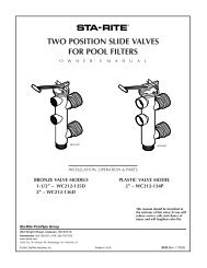
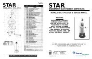
VERTICAL GRID DE FILTERS<br />
O W N E R’ S<br />
M A N U A L<br />
INSTALLATION, OPERATION & PARTS<br />
MODELS<br />
S7D75 S8D110<br />
This manual should be furnished to<br />
the end user of this filter; its use will<br />
reduce service calls and chance of injury<br />
and will lengthen filter life.<br />
Sta-Rite <strong>Pool</strong>/Spa Group<br />
293 Wright Street, Delavan, WI 53115<br />
International: 262-728-5551, FAX: 262-728-7550<br />
www.starite.com<br />
Union City, TN • Delavan, WI • Mississauga, Ont. • Murrieta, CA<br />
U.S. PATENT NO. 4995523 (Other patents pending)<br />
© 2004, Sta-Rite Industries Printed in U.S.A. S284 (Rev. 4/20/04)
VERTICAL GRID DE FILTERS<br />
To avoId unnee<strong>de</strong>d service calls, prevent possible injuries, and get the most<br />
out of your filter, READ THIS MANUAL CAREFULLY!<br />
The Sta-Rite System 3 <strong>Vertical</strong> Grid DE Filter:<br />
• Is <strong>de</strong>signed to filter water for swimming pools.<br />
• Is an excellent performer; durable, reliable.<br />
Table of Contents<br />
Safety Instructions .......................................................................................3<br />
General Information....................................................................................4<br />
Installation ..................................................................................................5<br />
Specifications..............................................................................................6<br />
Initial Startup...............................................................................................7<br />
Filter Disassembly / Assembly .....................................................................8<br />
Cleaning the Filter.......................................................................................9<br />
Filter Backwash Procedure.......................................................................9<br />
Manual Filter Cleaning Procedure..........................................................10<br />
Chemical Cleaning Procedure................................................................11<br />
System Inspection/Winterizing ..................................................................12<br />
Troubleshooting Gui<strong>de</strong>..............................................................................13<br />
Repair Parts List ...................................................................................14-15<br />
Warranty ...................................................................................................16<br />
2
READ AND FOLLOW SAFETY<br />
INSTRUCTIONS!<br />
This is the safety alert symbol. When you see this symbol on your filter<br />
or in this manual, look for one of the following signal words and be alert<br />
to the potential for personal injury.<br />
warns about hazards that will cause <strong>de</strong>ath, serious personal injury,<br />
or major property damage if ignored.<br />
warns about hazards that can cause <strong>de</strong>ath, serious personal injury,<br />
or major property damage if ignored.<br />
warns about hazards that will or can cause minor personal injury<br />
or property damage if ignored.<br />
NOTICE indicates special instructions not related to hazards.<br />
Carefully read and follow all safety instructions in this manual and on equipment.<br />
Keep safety labels in good condition; replace if missing or damaged.<br />
Incorrectly installed or tested equipment may fail, causing<br />
severe injury or property damage. Read and follow instructions<br />
in owner's manual when installing and operating equipment.<br />
Have a trained pool professional perform all pressure tests.<br />
1. Do not connect system to a high pressure or city water system.<br />
2. Use equipment only in a pool or spa installation.<br />
3. Trapped air in system can cause explosion. BE SURE all air is out of system<br />
before operating or testing equipment.<br />
Before pressure testing, make the following safety checks:<br />
• Check all clamps, bolts, lids, and system accessories before testing.<br />
• Release all air in system before testing.<br />
• Tighten Sta-Rite pump trap lids to 30 ft. lbs. (4.1 kg-cm) torque for testing.<br />
• Water pressure for test must be less than 25 PSI (172 kPa).<br />
• Water Temperature for test must be less than 100 o F. (38 o C).<br />
• Limit test to 24 hours. After test, visually check system to be sure it is ready<br />
for operation. Remove pump trap lid and retighten hand tight only.<br />
NOTICE: These parameters apply to Sta-Rite equipment only. For<br />
non-Sta-Rite equipment, consult equipment manufacturer.<br />
BEFORE WORKING<br />
ON FILTER:<br />
If filter clamps are<br />
adjusted or removed<br />
un<strong>de</strong>r pressure,<br />
tank may explo<strong>de</strong>,<br />
causing severe injury or<br />
major property damage.<br />
1. Stop pump.<br />
2. Open air release<br />
valve.<br />
3. Release all pressure<br />
from system.<br />
BEFORE WORKING<br />
ON PUMP OR MOTOR<br />
Filter pumps require<br />
hazardous voltage<br />
which can shock, burn,<br />
or cause <strong>de</strong>ath.<br />
Disconnect power<br />
to motor at main<br />
circuit breaker.<br />
Discharge motor<br />
capacitor to ground.<br />
3
GENERAL INFORMATION<br />
• Clean a new pool as well as possible before filling pool and operating filter.<br />
Excess dirt and large particles of foreign matter in the system can cause serious<br />
damage to the filter and pump.<br />
• With a diatomaceous earth (DE) filter system in place and operating correctly,<br />
clean water is returned to the pool faster than pool water is being<br />
contaminated. A typical pool installation will require approximately one<br />
week to obtain and maintain the sparkle that your filter is capable of giving<br />
you.<br />
• DO NOT use more than the recommen<strong>de</strong>d amount of DE in your filter. To<br />
do so can cause a buildup of DE and "bridging" between the elements<br />
which will plug the filter.<br />
If filter is improperly disassembled or assembled, it can explo<strong>de</strong> un<strong>de</strong>r<br />
pressure! To avoid danger of severe injury or major property damage,<br />
always follow service instructions in this manual when working on filter!<br />
Hazardous pressure.<br />
Can cause severe<br />
injury or major<br />
property damage<br />
from tank blow up.<br />
Release all pressure<br />
and read instructions<br />
before working on filter.<br />
NEVER operate this filter system at more than 50 pounds per square<br />
inch (50 PSI/345kPa) pressure! Be sure filter pressure gauge operates<br />
when system is operating. If pressure gauge is damaged or does not work, replace<br />
it.<br />
Purge all air from system before operating system. NEVER operate filter<br />
with air trapped insi<strong>de</strong>.<br />
• On a new pool installation, we recommend:<br />
1. Disassemble the filter after the initial cleanup.<br />
To prevent severe injury or major property damage, exactly follow "Filter<br />
Disassembly/Assembly Procedure" on Page 8.<br />
2. Remove and hose down the element assembly to remove contaminants.<br />
• It is a good i<strong>de</strong>a to remove the element assembly once a year and soak it in<br />
a filter cleaning solution to remove accumulated body oils, etc.; see Page<br />
11, "Chemical Cleaning Procedure".<br />
• Cleaning interval is based on pressure differential, not on length of time filter<br />
is operated. Different water conditions will have different normal cleaning<br />
intervals. If backwashing filter is not possible, use "Manual Filter<br />
Cleaning Procedure", Page 10, at regular intervals to clean filter.<br />
• Check local co<strong>de</strong>s for restrictions on backwash to waste piping, separation<br />
tank requirements and spent D.E. disposal requirements.<br />
4
INSTALLATION<br />
Installation of filter should only be done by qualified, licensed personnel.<br />
Filter mount must:<br />
• Provi<strong>de</strong> weather and freezing protection.<br />
• Provi<strong>de</strong> space and lighting for easy access for routine maintenance. (See<br />
Figure 1 and Table II, Page 6, for space requirements.)<br />
• Be on a reasonably level surface and provi<strong>de</strong> a<strong>de</strong>quate drainage.<br />
• Be as close to pool as possible to reduce line loss from pipe friction.<br />
TABLE I - Sta-Rite valves for<br />
use with DE <strong>filters</strong><br />
Port<br />
Size<br />
Part<br />
Number<br />
Multi-port<br />
2" 18201-0200*<br />
Plastic Sli<strong>de</strong><br />
2" WC212-134P*<br />
* Recommen<strong>de</strong>d for best energy<br />
conservation.<br />
NOTICE: Use of valves<br />
other than those listed<br />
above could cause<br />
reversed water flow<br />
through <strong>filters</strong> and<br />
damage to internal filter<br />
components.<br />
Piping:<br />
• Piping must conform to local/state plumbing and sanitary co<strong>de</strong>s.<br />
• Use Teflon tape or Plasto-Joint Stik' on all male connections of plastic pipe<br />
and fittings. DO NOT use pipe compounds on plastic pipe; it will cause the<br />
pipe to crack. Do not use sealant on unions—assemble them dry and hand<br />
tight.<br />
• Support pipe in<strong>de</strong>pen<strong>de</strong>ntly to prevent strains on filter or valve.<br />
• Use 2” (51mm) pipe to reduce pressure losses as much as possible.<br />
NOTICE: Filter may be located away from pool, but for a<strong>de</strong>quate flow larger<br />
pipe may be nee<strong>de</strong>d. Check local co<strong>de</strong>s for remote installation.<br />
• Fittings restrict flow; for best efficiency use fewest possible fittings.<br />
• Keep piping tight and free of leaks: pump suction line leaks may cause<br />
trapped air in filter tank or loss of prime at pump; pump discharge line leaks<br />
may show up as dampness or jets of water.<br />
• NOTICE: Overtightening can crack filter ports.<br />
Valves:<br />
• A check valve installed ahead of filter inlet will prevent contaminants from<br />
draining back into pool.<br />
• A check valve installed between filter and heater will prevent hot water<br />
from backing up into filter and <strong>de</strong>forming internal components.<br />
• Install Sta-Rite Two Position Sli<strong>de</strong> Valve or Multiport Selector Valve with filter.<br />
See Table I.<br />
• Filter ports and valve ports are furnished with union connections.<br />
DO NOT use pipe sealants on union collar (nut).<br />
• Use care before assembly not to damage union sealing surfaces or O Ring.<br />
• To allow recirculation during precoat (if precoat pot is used), install a recirculation<br />
line with shut-off between pad return line and pump suction.<br />
Electrical<br />
• All wiring, grounding and bonding of associated equipment must meet local<br />
and/or National Electrical Co<strong>de</strong> standards.<br />
1<br />
Lake Chemical Co., Chicago, IL<br />
5
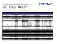
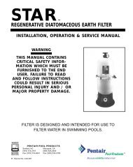
SPECIFICATIONS<br />
C<br />
D<br />
A<br />
E<br />
WATER OUTLET<br />
TO POOL<br />
WATER INLET<br />
PUMPED<br />
FROM POOL<br />
Figure 2 – Filter Cycle<br />
OUTLET<br />
B<br />
INLET<br />
7.812(198.4)<br />
9.19(233.4)<br />
WATER INLET<br />
PUMPED<br />
FROM POOL<br />
2" (51mm)Sta-Rite<br />
Union Connections<br />
FIGURE 1 – Dimensions in inches (mm)<br />
WASTE PORT TO<br />
SEPARATION TANK<br />
Figure 3 – Backwash Cycle<br />
TABLE II - SPACE REQUIREMENTS IN INCHES (MM)<br />
Mo<strong>de</strong>l No. A B C* D E<br />
Pressure Drop (PSI)<br />
8.0<br />
6.0<br />
4.0<br />
S7D75<br />
S8D110<br />
2.0<br />
0<br />
0 10 20 30 40 50 60 70 80 90 100 110 120<br />
Gallons Per Minute<br />
Pressure Drop Curve<br />
S7D75 28 1 ⁄2(724) 42(1067) 7 36(914) 53 1 ⁄2(1359)<br />
S8D110 32 1 ⁄2(826) 42 1 ⁄4(1074) 8 40(1020) 54 1 ⁄4(1378)<br />
* Number of clamps.<br />
TABLE III - APPROVED DE<br />
Use only the following DE or equal:<br />
Johns Manville Celite 545<br />
GREFCO Dicalite 4200<br />
Eagle-Picher<br />
Celatom<br />
TABLE IV - FILTER SPECIFICATIONS & OPERATING INFORMATION<br />
Filter Mo<strong>de</strong>l: S7D75 S8D110<br />
Filter Area in Sq. Ft. (M 2 ) 37 Sq. Ft. (3.44) 53 Sq. Ft. (4.92)<br />
Lbs. (Kg) of D.E. Used 3.7 (1.7) 5.3 (2.4)<br />
Max. Flow Rate in GPM (LPM) 74 (280) 106 (401)<br />
NSF Public <strong>Pool</strong> Flow Rate in GPM (LPM) 72 (280) 106 (401)<br />
Max. Operating Pressure in PSI (kPa) 50 (345) 50 (345)<br />
NOTICE: 1/2 pound of DE will fill a one-pound coffee can.<br />
6
INITIAL START-UP<br />
Be sure pump is OFF before starting procedure.<br />
Do not operate these <strong>filters</strong> at more than 50 PSI (345 kPa) un<strong>de</strong>r any<br />
circumstances!<br />
To prevent serious damage to the element fabric, NEVER run<br />
you DE filter without a diatomaceous earth precoat!<br />
Hazardous pressure.<br />
Can cause severe<br />
injury or major<br />
property damage<br />
from tank blow up.<br />
Release all pressure<br />
and read instructions<br />
before working on filter.<br />
To avoid damage to internal filter components, never change<br />
handle position on control valve while pump is running.<br />
1. Make sure all clamps are in place and knobs are securely hand-tight.<br />
2. Set valve to 'filter' position.<br />
3. Fill trap on pump with water.<br />
4. Open air release valve on top of filter assembly (Key No. 3, Page 14).<br />
5. Start pump to purge air from system.<br />
6. When steady stream of water comes from air release valve, close the<br />
valve.<br />
7. To prepare precoat slurry, mix diatomaceous earth (DE) and water. See<br />
Table IV or instruction <strong>de</strong>cal on filter shell for amount of DE to use.<br />
8. Empty slurry slowly into skimmer to precoat filter element with an even<br />
filtering cake.<br />
Close valve before air is drawn into system.<br />
NOTICE: To avoid bridging between filter <strong>grid</strong>s, do not use more DE than 0.1<br />
pound per square foot of filter area (0.49 kilos per square meter).<br />
After filter is operating, record filter pressure gauge reading in owner's manual<br />
for future use.<br />
NOTICE: When installed on a newly plastered pool, after approximately 48<br />
hours of operation disassemble filter and clean out plaster dust (see "Manual<br />
Filter Cleaning Procedure", Page 10).<br />
To avoid severe injury or major property damage, exactly follow instructions<br />
un<strong>de</strong>r "System Disassembly/Assembly" (Page 8)!<br />
Remove and thoroughly clean filter element assembly. Use cleanser or <strong>de</strong>tergent<br />
and a bottle brush to remove plaster dust (see Figures 8 and 9, Page 10).<br />
When installed on a pool with vinyl liner or painted bottom, thoroughly backwash<br />
and clean filter element after 48 hours of operation to remove construction<br />
<strong>de</strong>bris (see "Filter Backwash Procedure", Page 9).<br />
7
FILTER DISASSEMBLY/<br />
ASSEMBLY PROCEDURE<br />
To avoid equipment damage and personal injury, never change<br />
handle position on control valve while pump is running.<br />
BEFORE DISASSEMBLING FILTER:<br />
Hazardous pressure.<br />
Can cause severe<br />
injury or major<br />
property damage<br />
from tank blow up.<br />
Release all pressure<br />
and read instructions<br />
before working on filter.<br />
1. STOP PUMP.<br />
2. OPEN air release valve and drain fitting.<br />
3. WAIT until all pressure is released and water drained from filter tank<br />
and system before loosening clamp knobs.<br />
Disassembly:<br />
1. Backwash filter according to instructions un<strong>de</strong>r “Filter Backwash<br />
Procedure”, Page 9.<br />
2. Stop pump.<br />
3. Open air release valve (Key No. 3, Page 14) on top of filter tank to release<br />
all air pressure from insi<strong>de</strong> of tank and system.<br />
4. Remove filter drain plug and drain all water from tank.<br />
5. To equalize flange stresses, loosen clamp knobs alternately (that is, on opposite<br />
si<strong>de</strong>s of tank) around tank. Remove clamps.<br />
6. Being careful not to damage cord ring (Key No. 21, Page 14), lift upper<br />
tank shell (Key No. 7, Page 14) off lower tank shell (Key No. 20, Page 14).<br />
Assembly:<br />
1. Remove O-Ring slowly to avoid stretching or tearing it.<br />
2. Inspect O-Ring (Key No. 21, Page 14) for cuts, nicks, etc. If O-Ring is<br />
damaged, <strong>de</strong>formed, or has lost its resiliency, replace with a new one.<br />
3. Clean O-Ring area of tank shell (both halves) and O-Ring.<br />
4. Carefully install O-Ring and upper tank shell (Key No. 7, Page 14) on tank<br />
bottom (Key No. 20, Page 14).<br />
NOTICE: Do not lubricate O-Ring. Lubricants attract dirt and grit and may<br />
(especially when petroleum based) damage O-Ring and void warranty.<br />
NOTICE: Be sure upper tank shell contacts O-Ring surface evenly and<br />
seal area is clean and free from dirt.<br />
5. Install clamp bolts and clamps. Do not tighten clamps yet.<br />
6. See Figures 4 and 5 for clamp tightening sequence. Tighten all clamp<br />
knobs securely hand tight.<br />
NOTICE: To equalize stresses on tank, be sure to tighten clamps in sequence<br />
shown. DO NOT work your way around the filter tightening adjacent<br />
clamps.<br />
7. Install air relief valve and gauge assembly on tank.<br />
8
3<br />
5<br />
7<br />
1<br />
FIGURE 4 - 21" Filter clamp tightening<br />
sequence.<br />
3<br />
5<br />
8<br />
FIGURE 5 - 25" Filter clamp tightening<br />
sequence.<br />
1<br />
2<br />
2<br />
7<br />
6<br />
4<br />
6<br />
4<br />
CLEANING THE FILTER<br />
When to Clean:<br />
NOTICE: If installation does not allow backwashing, use manual cleaning procedure<br />
regularly (see Page 10).<br />
1. With a new filter:<br />
A. Record filter operating pressure at startup. When pressure reaches 15<br />
PSI (103kPa) above startup operation pressure, stop pump for 15-30<br />
seconds to allow filtering cake to release.<br />
B. Restart pump to form new cake. Pressure should now be less than 10<br />
PSI (69kPa) above startup operating pressure.<br />
C. If pressure is still more than 10 PSI (69kPa) above startup operating<br />
pressure, backwash filter (see below).<br />
2. Thoroughly clean air relief filter screen (Key No. 2, Page 15) on top of<br />
manifold EVERY time filter is opened. Be sure to remove all <strong>de</strong>bris from<br />
screen. Replace filter screen if damaged.<br />
3. At least twice a year, manually clean filter according to instructions, Page<br />
10. At least once a year, follow instructions un<strong>de</strong>r "Chemical Filter<br />
Cleaning Procedure", Page 11, as well.<br />
Filter Backwash Procedure:<br />
To prevent equipment damage and possible injury turn pump OFF<br />
before changing valve position.<br />
NOTICE: Before backwashing with a separation tank, review separation tank owner's<br />
manual for instructions.<br />
1. Stop pump.<br />
2. Change valve position.<br />
A. If using Multi-port Valve, set to backwash position.<br />
B. If using Two Position Sli<strong>de</strong> Valve, raise handle to fully exten<strong>de</strong>d position.<br />
3. Start pump, circulating water backwards through filter to flush cake and contaminants<br />
into separation tank or waste.<br />
4. If system has a sight glass, backwash until water in glass runs clear.<br />
5. If system does not have a sight glass:<br />
A. Backwash one minute.<br />
B. Stop pump; reset valve to 'FILTER' position.<br />
Stop pump before changing valve setting!<br />
C. Restart pump; filter for 20 seconds.<br />
D. Repeat steps A, B, C three times. Cycling is effective when cake and contaminants<br />
are difficult to break and flush out of filter.<br />
NOTICE: Do not vacuum pool while backwashing filter.<br />
6. Stop pump.<br />
7. Open air release valve and release ALL pressure from tank and system.<br />
8. Follow 'Disassembly' procedure, Page 8, to remove top of filter.<br />
Hazardous pressure. Risk of severe personal injury and<br />
major property damage if tank is opened while un<strong>de</strong>r pressure or while<br />
pump is running.<br />
9
9. If any DE remains on <strong>grid</strong>s after backwashing, flush filter elements with<br />
gar<strong>de</strong>n hose to remove it. Be sure to comply with local co<strong>de</strong> for waste DE<br />
disposal.<br />
10. Follow instructions un<strong>de</strong>r 'Assembly', Page 8, to reassemble filter.<br />
11. Follow 'Initial Start-up' procedure (Page 7, steps 4, 5, 6 and 7) to restart<br />
system.<br />
Union<br />
Collar<br />
Manifold<br />
Element<br />
Assembly<br />
O-Ring<br />
FIGURE 6<br />
1215 0497<br />
FIGURE 7<br />
Hazardous pressure.<br />
Can cause severe<br />
injury or major<br />
property damage<br />
from tank blow up.<br />
Release all pressure<br />
and read instructions<br />
before working on filter.<br />
1216 0497<br />
12. Compare pressure reading on gauge with reading recor<strong>de</strong>d after initial<br />
startup. The two readings should be very close; if not, do "Manual Filter<br />
Cleaning Procedure", below.<br />
MANUAL FILTER<br />
CLEANING PROCEDURE<br />
Before Disassembling Filter:<br />
1. STOP PUMP.<br />
2. OPEN air release valve.<br />
3. WAIT until all pressure is released from filter tank and system<br />
before loosening clamps.<br />
NOTICE: At least twice a year, disassemble and clean filter regardless of operating<br />
pressure readings. This can be done conveniently while winterizing pool<br />
in cold climates. Use this method regularly if no means of backwashing is<br />
available.<br />
1. Backwash filter as usual, but do not precoat.<br />
2. Disassemble filter (see Page 8).<br />
To avoid severe injury or major property damage, exactly follow instructions<br />
un<strong>de</strong>r “Disassembly” (Page 8)!<br />
3. Unscrew union collar holding element assembly in position.<br />
NOTICE: Be careful not to lose O-Ring.<br />
4. Grasp element assembly at manifold (Figure 6) and remove it.<br />
5. Hose down element assembly and clean with bottle brush (Figure 7). Use<br />
<strong>de</strong>tergent solution or filter cleanser available from a pool service store.<br />
NOTICE: To avoid damaging fabric, do not allow filter element to rub on<br />
concrete or any abrasive surface during cleaning.<br />
NOTICE: Do not expose element cloth to direct sun for long periods.<br />
Direct sun will cause the cloth to <strong>de</strong>teriorate.<br />
6. Inspect <strong>grid</strong> cloth for tears, calcification, plugged areas, etc. If necessary,<br />
soak element in filter cleanser to remove buildup of oils, etc. If calcified,<br />
consult pool service company or factory for instructions.<br />
7. Thoroughly clean air relief filter screen (Key No. 2, Page 15) on top of<br />
manifold. Be sure to remove all <strong>de</strong>bris from screen.<br />
8. Inspect O-Ring out of the internal union (see Figure 6) for damage.<br />
Reinstall it in the groove in the union half if it is undamaged; if it shows<br />
tears or cuts replace it.<br />
9. Replace filter element in tank and tighten union firmly hand tight. Union<br />
10
collars may need to be cleaned before reassembly.<br />
10. Follow filter assembly procedure, Page 8.<br />
To avoid severe injury or major property damage, exactly follow<br />
instructions un<strong>de</strong>r “Assembly” (Page 8)!<br />
11. If unit is returning to service, see “Initial Startup”, Page 7.<br />
12. If cleaning is part of seasonal shutdown, see “Winterizing”, Page 12.<br />
Hazardous pressure.<br />
Can cause severe<br />
injury or major<br />
property damage<br />
from tank blow up.<br />
Release all pressure<br />
and read instructions<br />
before working on filter.<br />
CHEMICAL CLEANING<br />
PROCEDURE<br />
Before Disassembling Filter:<br />
1. STOP PUMP.<br />
2. OPEN air release valve.<br />
3. WAIT until all pressure is released from filter tank and system<br />
before loosening clamps.<br />
NOTICE: Do not expose element cloth to direct sunlight for long periods.<br />
Direct sunlight will cause the cloth to <strong>de</strong>teriorate.<br />
NOTICE:To avoid damaging fabric, do not allow filter element to rub on concrete<br />
or any abrasive surface during cleaning.<br />
NOTICE: Clean filter manually before doing any chemical cleaning.<br />
Filter Disassembly:<br />
To avoid severe injury or major property damage exactly follow<br />
instructions un<strong>de</strong>r “Disassembly” (Page 8)!<br />
1. Disassemble and inspect element <strong>grid</strong> assemblies for tears and worn<br />
areas. Replace as nee<strong>de</strong>d.<br />
2. Rinse each <strong>grid</strong> thoroughly with water.<br />
3. Wash each <strong>grid</strong> with a mild soap solution or commercial filter cleaner. If<br />
necessary, soak element <strong>grid</strong>s in filter cleanser to remove buildup of oils,<br />
etc.<br />
4. Rinse thoroughly to remove all soap film.<br />
5. If filter elements do not come clean after soaking, have your pool professional<br />
acid clean them.<br />
Risk of burns, explosions, and environmental damage. Only<br />
trained professionals should attempt to acid clean filter elements.<br />
7. Reassemble element <strong>grid</strong>s.<br />
8. Inspect insi<strong>de</strong> of filter tank and remove any <strong>de</strong>bris which remains after<br />
backwashing.<br />
9. Thoroughly clean air relief filter screen (Key No. 2, Page 15) on top of<br />
manifold. Be sure to remove all <strong>de</strong>bris from screen. Replace filter screen if<br />
damaged.<br />
10. Follow filter assembly procedure, Page 8.<br />
To avoid severe injury or major property damage, follow instructions<br />
un<strong>de</strong>r “Assembly” (Page 8)!<br />
11. If unit is returning to service, see “Initial Startup”, Page 7.<br />
11
l2. If cleaning is part of seasonal shutdown, see “Winterizing”, Page 12.<br />
SYSTEM INSPECTION<br />
General:<br />
Wash outsi<strong>de</strong> of filter with a mild <strong>de</strong>tergent and water. Rinse off with hose.<br />
NOTICE: DO NOT use solvents to clean filter; solvents may damage plastic<br />
components in system.<br />
NOTICE: Open air bleed valve and bleed all air from filter each time pump is<br />
stopped and restarted.<br />
Weekly Inspection:<br />
1. Skimmer basket- remove <strong>de</strong>bris.<br />
2. Stop pump, release all pressure. Remove trap cover and basket, remove <strong>de</strong>bris.<br />
3. Bleed air from filter each time system is started.<br />
4. For systems with bypass valve, make sure separation tank is not un<strong>de</strong>r<br />
pressure.<br />
5. Check pump for leaks. If found, see pump owner's manual.<br />
6. Check pump strainer lid for tightness. Do not over-tighten!<br />
WINTERIZING<br />
1. Clean filter according to instructions, Page 10, before winterizing. Do not<br />
winterize with DE precoat on <strong>grid</strong>s or with residual in tank.<br />
2. Open air release valve; open all system valves. Position multiport valve<br />
between port positions to allow passage to all ports.<br />
3. Remove drain plugs from trap, pump, valve, filter and separation tank.<br />
4. Drain system piping.<br />
5. Loosen union nuts to drain water from filter internal piping and valve.<br />
6. Cover with plastic or tarpaulin to prevent water entrance and freezing.<br />
12
TROUBLESHOOTING GUIDE<br />
1. Short Cycle between backwashes:<br />
NOTICE: Time between backwashes will vary with each installation and between<br />
different areas of the country. The following causes and remedies are<br />
for cycle times shorter than normal for your area.<br />
A. Chlorine residual too low; maintain proper residual (consult pool professional<br />
for recommendation).<br />
B. Flow rate too high; restrict flow to rated capacity of filter (see instruction<br />
plate on filter or specifications on Page 6).<br />
C. Filter too small; install larger filter or additional filter.<br />
D. Improper/insufficient precoat; see precoat instructions (Page 7).<br />
E. Filter elements plugged; thoroughly clean filter (see No. 4, "Plugged<br />
Grid Cloth", below, and "Manual Filter Cleaning Procedure", Page 10).<br />
F. Insufficient cleaning during backwash or annual cleaning; review<br />
cleaning instructions, Pages 9-11.<br />
G. Too much DE; check for bridging between filter elements.<br />
H. Water is chemically out of balance; consult pool professional.<br />
2. Low Flow/High Pressure:<br />
A. Elements plugged; clean filter thoroughly (see Pages 9-11).<br />
B. Pipe blocked downstream from filter; remove obstruction.<br />
C. Piping too small; use larger pipe (consult <strong>de</strong>aler for sizing).<br />
D. Filter area too small; install larger filter or auxiliary filter (consult <strong>de</strong>aler<br />
for recommendation)<br />
3. Low Flow/Low Pressure:<br />
A. Pump too small; consult <strong>de</strong>aler for recommendations.<br />
B. Plugged pump or plugged hair and lint trap; clean thoroughly.<br />
4. Plugged Grid Cloth:<br />
A. Insufficient precoat; see precoat instructions (Page 7).<br />
B. Insufficient cleaning; follow cleaning instructions closely and clean<br />
thoroughly (see Pages 9-11).<br />
C. Water is chemically out of balance; consult pool service man.<br />
D. Excessive air in filter; non-precoated areas may plug. Vent air from tank<br />
and check for pump suction pipe leaks. Clean air bleed filter in <strong>grid</strong> assembly.<br />
5. <strong>Pool</strong> Water Not Clean:<br />
A. Chlorine dosage too low; maintain a<strong>de</strong>quate chlorine residual (consult<br />
pool service man for recommendation).<br />
B. Broken filter elements passing DE into pool; replace <strong>de</strong>fective <strong>grid</strong>s.<br />
C. Insufficient or improper precoat; follow precoating instructions and use<br />
recommen<strong>de</strong>d amount of DE (see Page 7).<br />
D. Ina<strong>de</strong>quate turnover rate; consult <strong>de</strong>aler to verify that equipment is<br />
properly sized for your pool.<br />
13
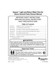
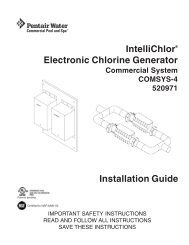
15<br />
20<br />
10<br />
5<br />
0<br />
25<br />
30<br />
35<br />
60<br />
40<br />
55<br />
45<br />
50<br />
21 1<br />
3 2<br />
4<br />
5<br />
6<br />
MODELS<br />
S7D75<br />
S8D110<br />
7<br />
8<br />
9<br />
20<br />
10<br />
17<br />
18<br />
19<br />
11<br />
14<br />
13<br />
12<br />
16<br />
14<br />
15<br />
1460 0497<br />
REPAIR PARTS LIST<br />
Key Part Mo<strong>de</strong>l No.<br />
No. Description S7D75 S8D110<br />
1 2 Inch Gauge 33600-0023 33600-0023<br />
2 Air Release Valve WC212-120P WC212-120P<br />
3 Close Nipple 1/4 in. U37-16P U37-16P<br />
4 Adapter Bushing 24900-0504 24900-0504<br />
5 O-Ring 35505-1423 35505-1423<br />
6 Upper Tank Shell Kit* 24851-9000 24851-9001<br />
7 Filter Element Assembly 23900-1220 23900-1221<br />
8 O-Ring U9-362 U9-362<br />
9 Outlet Assembly 23911-0102 23911-0102<br />
10 Inlet Assembly 23911-0100 23911-0101<br />
11 O-Ring 35505-1425(2) 35505-1425(2)<br />
12 1-1/2" NPT Plug 27001-0022S 27001-0022S<br />
13 Adapter Fitting 24900-0509 24900-0509<br />
14 O-Ring 35505-1424 (2) 35505-1424(2)<br />
15 Drain Plug 24900-0503 24900-0503<br />
16 Bulkhead Retaining Nut 24752-0050(2) 24752-0050(2)<br />
17 Clamp Assembly 24850-0101 (7) 24850-0101 (8)<br />
18 Clamp Bolt 24850-0010(7) 24850-0010(8)<br />
19 Lower Tank Shell 24850-0102 24851-0103<br />
20 Tank O-Ring 24850-0008 24850-0009<br />
21 Valve and Gauge Assembly (Inclu<strong>de</strong>s Key Nos. 1-5) 24850-0105 24850-0105<br />
• Warning Decal 32165-4004 32165-4005<br />
• Decal - Mo<strong>de</strong>l Label 32155-4031 32155-4033<br />
• Decal - Instruction Label 32155-4032 32155-4034<br />
• Not illustrated Quantity one unless otherwise indicated ( ).<br />
* Inclu<strong>de</strong>s all <strong>de</strong>cals and labels.<br />
14
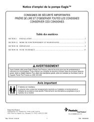
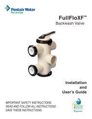
1<br />
2<br />
3<br />
FILTER ELEMENT ASSEMBLY FOR S7D75<br />
4<br />
5<br />
6<br />
7<br />
8<br />
1063 0497<br />
10<br />
11<br />
9<br />
Key Part No. Part No.<br />
No. Description Used 23900-1220<br />
1 Wing Nut 2 35402-0074<br />
2 Air Bleed Assembly 1 24800-0120<br />
3 Manifold 1 24800-0100<br />
4 Covered Element 12-7/16" 1 23900-1171<br />
5 Covered Element 13-13/16" 2 23900-1170<br />
6 Covered Element 16-1/2" 2 23900-0033<br />
7 Covered Element 15-3/16" 2 23900-1174<br />
8 Covered Element 12-7/16" 2 23900-1175<br />
9 Covered Element 9-11/16" 2 23900-1173<br />
10 Element Grid Support 1 23900-0350<br />
11 Rod 2 23900-0039<br />
1<br />
2<br />
3<br />
FILTER ELEMENT ASSEMBLY FOR S8D110<br />
4<br />
Key Part No. Part No.<br />
No. Description Used 23900-1221<br />
9<br />
10<br />
5<br />
6<br />
1064 0497<br />
7<br />
8<br />
1 Wing Nut 2 35402-0074<br />
2 Air Bleed Assembly 1 24800-0120<br />
3 Manifold 1 24801-0101<br />
4 Covered Element 16-1/2" 3 23900-1172<br />
5 Covered Element 19-5/16" 4 23900-0144<br />
6 Covered Element 16-1/2" 2 23900-0033<br />
7 Covered Element 15-3/16" 2 23900-1174<br />
8 Covered Element 11" 2 23900-0032<br />
9 Element Grid Support 1 23901-0350<br />
10 Rod 2 23900-0039<br />
15
Pumps, <strong>filters</strong>, skimmers, un<strong>de</strong>rwater lights (except bulbs),<br />
accessories and fittings manufactured by Sta-Rite are warranted<br />
to be free of <strong>de</strong>fects in material and workmanship for<br />
one (1) year from date of installation.<br />
Year from date<br />
Product specific warranties:<br />
of installation<br />
HRPB, DEPB, System 3, and PL – Tanks . . . . . . . .10 years<br />
Internal filter components and valves . . . . . . . . . 1 year<br />
Max-E-Therm – <strong>Pool</strong>/Spa Heaters . . . . . . . . . . . . . 2 years<br />
Heater Enclosure only (Upper RH & LH;<br />
lower enclosure; and control board enclosure)… 10 years<br />
Automatic <strong>Pool</strong> Cleaners including Hose . . . . . . . 2 years<br />
Cristal-Flo <strong>filters</strong> – Tanks . . . . . . . . . . . .10 years pro-rated*<br />
Valve and internal components. . . . . . . . . . . . . . . . 1 year<br />
Posi-Flo II – Tanks . . . . . . . . . . . . . . . . . . . . . . . . . .10 years<br />
Elements . . . . . . . . . . . . . . . . . . . . . . . . . . . . . . . . 1 year<br />
PRC Cartridge –<br />
Filter Tanks . . . . . . . . . .5 years pro-rated (1st 2 years full)<br />
Elements . . . . . . . . . . . . . . . . . . . . . . . . . . . . . . . . 1 year<br />
System 2 Above Ground Systems – Tanks . . . . . . .10 years<br />
Pumps / Platform and Internals . . . . . . . . . . . . . . . 1 year<br />
Pumps . . . . . . . . . . . . . . . . . . . . . . . . . . . . . . . . . . . . . 1 year<br />
When equipped with A.O. Smith<br />
2-compartment motors (Does not inclu<strong>de</strong><br />
pumps sold as part of a systems package) . . . . . . 2 years<br />
Traps / In-Line Strainers . . . . . . . . . . . . . . . . . . . . . 1 year<br />
<strong>Vertical</strong> Commercial Filter – Tanks . . . . . . . . . . . .10 years<br />
Internals . . . . . . . . . . . . . . . . . . . . . . . . . . . . . . . . . 1 year<br />
Horizontal Commercial Filter<br />
Tanks . . . . . . . . . . . . . . . . . . . . . . . . . . . . . . . . . . .5 years<br />
(Years 6-9, Prorated <strong>de</strong>clining 20%/year, Yr. 10 - 10%)<br />
Internals . . . . . . . . . . . . . . . . . . . . . . . . . . . . . . . . . 1 year<br />
STA-RITE LIMITED WARRANTY<br />
* Full warranty coverage is in effect for one year after installation.<br />
The pro-rated warranty covers the tank only during<br />
the 2nd through 10th year after installation. The amount covered<br />
<strong>de</strong>creases by 10% each year. (ie., 2nd year 90% covered,<br />
3rd year 80% covered, etc.).<br />
The foregoing warranties relate to the original consumer purchaser<br />
(“Purchaser”) only. Sta-Rite shall have the option to repair<br />
or replace the <strong>de</strong>fective product, at its sole discretion.<br />
Purchasers must pay all labor and shipping charges necessary<br />
to replace the product covered by this warranty. Requests for<br />
warranty service must be ma<strong>de</strong> through the installing <strong>de</strong>aler.<br />
This warranty shall not apply to any product that has been<br />
subject to negligence, misapplication, improper installation<br />
or maintenance, or other circumstances which are not in<br />
Sta-Rite’s direct control.<br />
This warranty sets forth Sta-Rite’s sole obligation and<br />
Purchaser’s exclusive remedy for <strong>de</strong>fective products.<br />
STA-RITE SHALL NOT BE LIABLE FOR ANY CONSEQUENTIAL,<br />
INCIDENTAL OR CONTINGENT DAMAGES WHATSOEVER.<br />
THE FOREGOING WARRANTIES ARE EXCLUSIVE AND IN<br />
LIEU OF ALL OTHER EXPRESS WARRANTIES. IMPLIED WAR-<br />
RANTIES, INCLUDING BUT NOT LIMITED TO THE IMPLIED<br />
WARRANTIES OF MERCHANTABILITY AND FITNESS FOR A<br />
PARTICULAR PURPOSE, SHALL NOT EXTEND BEYOND THE<br />
DURATION OF THE APPLICABLE EXPRESS WARRANTIES<br />
PROVIDED HEREIN.<br />
Some states do not allow the exclusion or limitation of inci<strong>de</strong>ntal<br />
or consequential damages or limitations on how long<br />
an implied warranty lasts, so the above limitations or exclusion<br />
may not apply to you. This warranty gives you specific<br />
legal rights and you may also have other rights which vary<br />
from state to state.<br />
Superse<strong>de</strong>s all previous publications.<br />
Sta-Rite Industries<br />
293 Wright St., Delavan, WI 53115<br />
▲ Retain Warranty Certificate (upper portion) in a safe and convenient location for your records.<br />
DETACH HERE: Fill out bottom portion completely and mail within 10 days of purchase/installation to:<br />
▼ Sta-Rite, Attn: Warranty Dept., 293 Wright St., Delavan, WI 53115<br />
Warranty Registration Card<br />
Name<br />
Address<br />
Years pool has been in service ■ less than 1 ■ 1-3 ■ 3-5 ■ 5-10<br />
Purchased from:<br />
Company name<br />
City State Zip<br />
Purchase Date<br />
Address<br />
City State Zip<br />
Product Purchased<br />
■ New installation<br />
■ Replacement<br />
Please send me more information on these<br />
other products from Sta-Rite.<br />
Type of <strong>Pool</strong> ■ Inground ■ Vinyl ■ Fiberglass ■ Gunite<br />
Size of <strong>Pool</strong><br />
■ Pumps ■ Filters ■ Automatic <strong>Pool</strong> Cleaners<br />
■ Maintenance Equipment ■ Test Strips<br />
■ Heaters<br />
S4877PS (Rev. 2/4/03)