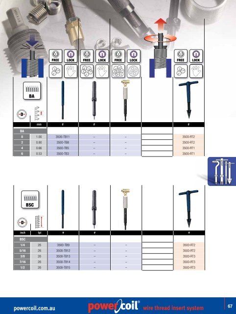
FREE LOCK FREE LOCK FREE LOCK FREE LOCK 304 BA D 304 mm # # # BA 0 1.00 3500-TB11 – – 3500-RT2 2 0.80 3500-TB8 – – 3500-RT2 4 0.66 3500-TB5 – – 3500-RT1 6 0.53 3500-TB3 – – 3500-RT1 304 BSC D inch tpi # # # BSC 1/4 26 304 3500-TB9 – – 3500-RT2 5/16 26 3500-TB12 – – 3500-RT2 3/8 26 3500-TB13 – – 3500-RT3 7/16 26 3500-TB14 – – 3500-RT3 1/2 26 3500-TB15 – – 3500-RT3 <strong>powercoil</strong>.<strong>com</strong>.<strong>au</strong> ® <strong>wire</strong> <strong>thread</strong> <strong>insert</strong> <strong>system</strong> 67
® ® Materials PowerCoil standard <strong>insert</strong>s are manufactured from fully certified, aircraft quality, 304 (18/8) <strong>au</strong>stenitic stainless steel in accordance with DTD 734A. Alternative materials include 316 stainless steel and a variety of application specific surface coatings. Alternative Materials Phosphor Bronze Non ferrous copper/tin alloy in accordance with BS2783 PB 102 EH – is suitable for operation in temperatures ranging from -200ºC to +300ºC. Inconel X-750 Heat resisting precipitation hardenable nickel base alloy (equivalent specifications SAE AS 7246, DIN/NF 3018, W.NR 2.4669, UNS N07750). Inconel X-750 is suitable for operation in temperatures ranging from -200ºC to +550º degrees celsius. Nimonic 90 Heat resisting precipitation hardenable nickel base alloy in accordance with BS2 HR 501 (equivalent specifications W.NR 2.4632, UNS N07090). Nimonic 90 is suitable for operation in temperatures ranging from -100ºC to +650º degrees celsius. Insert Material Max. Temperature Typical Applications Coatings Peak Continuous Stainless 304 425ºC 315ºC Most general applications FL, AG, CD 800ºF 600ºF in all materials Stainless 316 425ºC 315ºC Increased corrosion resistance FL, AG, CD 800ºF 600ºF for salt water applications Phosphor Bronze 300ºC 235ºC Copper parts, non-magnetic, AG, CD 572ºF 455ºF low permeability applications Iconel X-750 650ºC 550ºC Aerospace, turbines, corrosive AG 1200ºF 1020ºF environments, high temp. use Nimonic 90 650ºC 550ºC Aerospace and AG 1200ºF 1020ºF turbine applications Alternative Finishes & Coatings Cadmium Plate Electro-deposited Cadmium in accordance with DTD 904/Def Stan 03-19 (equivalent specifications FED. QQ-P-416, LN 9368). Cadmium plating provides an excellent barrier between dissimilar metals dramatically reducing the effects of galvanic corrosion, its high lubricity and excellent corrosion resistance prevents seizure and galling between <strong>thread</strong>ed <strong>com</strong>ponents. Cadmium plate is suitable for operation in temperatures ranging from -200ºC to +235ºC. Cadmium plated parts must not be • sujected to temperatures exceeding 235ºC (455ºF) • <strong>com</strong>e into contact with fuel or hot oil • <strong>com</strong>e into contact with food or drinking water • be used with titanium <strong>com</strong>ponents (either directly or indirectly).At elevated temperatures embrittlement and subsequent <strong>com</strong>ponent failure may occur. • Cadmium is highly toxic – consequently extreme care must be taken when shipping, handling and installing. Zinc Plate Electrolytically deposited zinc in accordance with BS 3382. Electro-deposited zinc is the most widely applied electroplated finish in industry. Zinc is suitable for operation in temperatures ranging from -200ºC to +250ºC. Silver Plate Electrolytically deposited silver in accordance with DTD 939. Silver plating is used to prevent seizure and galling between <strong>thread</strong> <strong>com</strong>ponents in high temperature applications and is most <strong>com</strong>monly applied to aero-engine fasteners. Silver plate is suitable for operation in temperatures ranging from -200ºC to +650ºC. Silver plated <strong>wire</strong> <strong>insert</strong>s may be installed in various materials including aluminium alloys, magnesium alloys, corrosion and heat resistant materials etc. Silver plated <strong>insert</strong>s are not re<strong>com</strong>mended for installation in titanium alloy which may exceed a service temperature of 300ºC ( 570ºF). Stress corrosion as a result of the <strong>com</strong>bination of silver and titanium may occur in the housing material. Dry Film Lubricant Solid film heat cured molybdenum disulphide dry film lubricant coating in accordance with MIL-L-0046010 provides a low frictional coefficient coating with excellent load bearing capabilities. Dry film lubricant prevents seizing and galling between <strong>thread</strong>ed <strong>com</strong>ponents and is particularly effective in screw locking <strong>insert</strong> applications. Dry film lubricant is suitable for operation in temperatures ranging from -100ºC to +250ºC. Plating / Finish Part No. Suffix Applicable Process Specification Silver Plating AG DTD 939 Cadmium Plating CD QQP-416 or DEF STD 03-19 Dry Film Lubricant FL MIL-L-8937 or MIL-L-46010 Red Dye – Applied to locking <strong>insert</strong>s for identification purposes* * other color dyes may also be utilised for specific identification purposes Selection of Correct Insert Length PowerCoil <strong>wire</strong> <strong>thread</strong> <strong>insert</strong>s are available in all popular <strong>thread</strong> types. Five <strong>insert</strong> lengths are available for each <strong>thread</strong> size. It is important to select the correct <strong>insert</strong> length in order to balance the bolt tensile strength against the shear strength of the parent material. The five <strong>insert</strong> lengths (re<strong>com</strong>mended <strong>thread</strong> engagement of the PowerCoil <strong>wire</strong> <strong>thread</strong> <strong>insert</strong>), 1D, 1.5D, 2D, 2.5D and 3D are shown in the shaded area of the table below. These are calculated numbers since the <strong>insert</strong>s cannot be measured in the free (un-installed) state. The numbers are multiples of the nominal <strong>thread</strong> size, or diameter, of the <strong>insert</strong>. The actual <strong>insert</strong> lengths in the installed position are listed in the <strong>insert</strong> selection tables. There they represent the actual installed length plus 1/2 pitch. Using the table below, an <strong>insert</strong> length can be selected which will produce a <strong>thread</strong> <strong>system</strong> strong enough to fracture a bolt before it will strip or damage either the parent material or the <strong>insert</strong>. Re<strong>com</strong>mended Nominal Insert lengths Based on Parent Material Versus Bolt Material Strengths UNIFIED (source BS7752 Part 1:1994) Shear Strength of Bolt Material Minimum Parent Material (KSI) Ultimate Tensile Strength (KSI) 54 75 96 108 125 132 160 180 220 10 2.0 2.5 3.0 3.0 – – – – – 15 1.5 1.5 2.0 2.5 2.5 3.0 – – – 20 1.0 1.5 1.5 2.0 2.0 2.0 2.5 3.0 3.0 25 1.0 1.0 1.5 1.5 1.5 2.0 2.0 2.5 2.5 30 1.0 1.0 1.0 1.5 1.5 1.5 2.0 2.0 2.5 40 1.0 1.0 1.0 1.0 1.0 1.5 1.5 1.5 2.0 50 1.0 1.0 1.0 1.0 1.0 1.0 1.0 1.5 1.5 EXAMPLE: If parent material shear strength is 10KSI and the bolt tensile strength is 54 KSI, the correct <strong>insert</strong> length is 2.0 diameters (2D). METRIC Shear Strength of Bolt Material Minimum Parent Material (MPa) Ultimate Tensile Strength (MPa) 300 400 500 600 800 1000 1200 1400 70 1.5 2.0 2.5 2.5 – – – – 100 1.0 1.5 1.5 2.0 2.5 3.0 – – 150 1.0 1.0 1.5 1.5 2.0 2.0 2.5 3.0 200 1.0 1.0 1.0 1.0 1.5 1.5 2.0 2.5 250 1.0 1.0 1.0 1.0 1.0 1.5 1.5 2.0 300 1.0 1.0 1.0 1.0 1.0 1.5 1.5 1.5 350 1.0 1.0 1.0 1.0 1.0 1.0 1.5 1.5 EXAMPLE: If parent material shear strength is 150Mpa and the bolt tensile strength is 600Mpa, the correct <strong>insert</strong> length is 1.5 diameters (1.5D). Bolt Projection PowerCoil <strong>wire</strong> <strong>thread</strong> <strong>insert</strong>s are designed to be used with standard, readily available bolts and screws that require no special hardware. ® 68 <strong>wire</strong> <strong>thread</strong> <strong>insert</strong> <strong>system</strong> <strong>powercoil</strong>.<strong>com</strong>.<strong>au</strong>