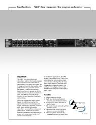
SMRTM821 Stereo Mic/Line Program Audio Mixer ... - Peavey.com
SMRTM821 Stereo Mic/Line Program Audio Mixer ... - Peavey.com
SMRTM821 Stereo Mic/Line Program Audio Mixer ... - Peavey.com

You also want an ePaper? Increase the reach of your titles
YUMPU automatically turns print PDFs into web optimized ePapers that Google loves.
Configuration<br />
The next step is to configure the SMR 821’s many rear panel switches for your application. Although the unit is<br />
shipped from the factory with default switch values, you should make sure that these settings are correct for YOUR<br />
application. Let’s take a look at each one, and describe their functionality.<br />
First, there are the Channels 1-6 Bus Assign Switches. These switches provide<br />
the ability to assign each input to the Left, Right or Aux output buses. In addition,<br />
you can turn on or off the phantom power on each channel. There is a single<br />
8-position DIP switch for each TWO input channels. Take care that you are<br />
adjusting the correct switch for the correct channel. It is re<strong>com</strong>mended that you<br />
use a small screwdriver or other instrument to set the switches. Do not force<br />
them. Also, keep in mind that the ON position is on top. Figure 10 shows the DIP<br />
switches with all functions in the ON position. NOTE: The factory setting is all<br />
bus assign switches ON, and phantom OFF.<br />
Figure 11. <strong>Mic</strong> Mix, Rt Out Mute<br />
and Low Cut Switches<br />
About the middle of the rear panel, you will find a<br />
group of three switches. They include the <strong>Mic</strong> Mix<br />
switch, the Rt Out Mute switch and the Low Cut switch. The <strong>Mic</strong> Mix switch allows<br />
the summed signal of Channels 1-6 to be routed before or after the remote L/R volume control.<br />
In the “Pre Remote” position, the signals from Channels 1-6 are affected by the remote<br />
volume control along with the stereo input from the either Channel 7 or 8. In the Post<br />
Remote position, only the stereo input from either Channel 7 or 8 is affected by the remote<br />
volume control. The factory default setting is “Pre-Remote”.<br />
The Rt Out Mute switch controls the muting of the right mix bus. The factory setting of<br />
this switch is “Enable”. When enabled, the left and right mix buses are affected by the<br />
activity of the Channel 1 muting circuit. When this switch is defeated, only the left bus is<br />
affected by the muting circuit. Use the Channel 1 Mute Threshold control to set the trigger point to activate the muting.<br />
The Low Cut Switch enables a filter with a corner frequency of 100 Hz and is helpful to filter out rumble, wind noise,<br />
breath thumps, and other low-frequency signals that rob amplifier power and muddy the mix. Enabling this switch<br />
will affect Channels 1-6 only. The factory default setting for the Low Cut switch is “Defeat” or “Flat”.<br />
The Mode switch selects either <strong>Stereo</strong> mode or Mono mode for Channel 7 or 8. In<br />
the <strong>Stereo</strong> mode, the Left input signal feeds the Left mix bus and the Right input<br />
signal feeds the Right mix bus via the front panel Level control. In the Mono mode,<br />
the summed Left and Right input signals feed both Left and Right mix buses. This<br />
allows for a mono source to be used to feed the stereo mix buses. Additionally, it<br />
allows for Left and Right outputs of the source to be summed without a Y-cable. In<br />
either mode, a summed mono signal feeds the Aux mix bus. The factory default is<br />
“<strong>Stereo</strong>”.<br />
Figure 10. Input Channel Bus Assign<br />
Switches and Input Connectors<br />
The EQ switch places the 4-band stereo equalizer in or out of the Left and Right signal<br />
paths. In the OUT position the equalizer is<br />
<strong>com</strong>pletely bypassed. The factory default is IN.<br />
Figure 12. Channel 7 & 9 Mode Switches<br />
The Bus Link switch is used to place the mixer in the master or slave mode of operation.<br />
A stand-alone unit should always be in the master mode, and the factory<br />
default is MASTER. See the “Connections” section of this manual for details on Bus<br />
Linking and using multiple SMR 821’s.<br />
Figure 13. Channel 7 & 9 Mode Switches<br />
That’s about it for configuration. As you can see, the SMR 821 provides many powerful<br />
features for better, more cost effective systems. The multiple <strong>com</strong>binations of<br />
routing, control and input assignment facilitate a wide range of applications.<br />
<strong>Peavey</strong> Electronics Corp<br />
Page 13