PCX-U12 - Peavey.com
PCX-U12 - Peavey.com
PCX-U12 - Peavey.com

You also want an ePaper? Increase the reach of your titles
YUMPU automatically turns print PDFs into web optimized ePapers that Google loves.
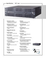
P<br />
C<br />
X<br />
-<br />
U<br />
1<br />
2<br />
True<br />
diversity<br />
UHF<br />
wireless<br />
receiver<br />
OPERATING GUIDE
Intended to alert the user to the presence of uninsulated “dangerous voltage” within<br />
the product’s enclosure that may be of sufficient magnitude to constitute a risk of<br />
electric shock to persons.<br />
Intended to alert the user of the presence of important operating and maintenance<br />
(servicing) instructions in the literature ac<strong>com</strong>panying the product.<br />
CAUTION: Risk of electrical shock — DO NOT OPEN!<br />
CAUTION: To reduce the risk of electric shock, do not remove cover. No user serviceable<br />
parts inside. Refer servicing to qualified service personnel.<br />
WARNING: To prevent electrical shock or fire hazard, do not expose this appliance to rain<br />
or moisture. Before using this appliance, read the operating guide for further warnings.<br />
Este símbolo tiene el propósito, de alertar al usuario de la presencia de “(voltaje)<br />
peligroso” sin aislamiento dentro de la caja del producto y que puede tener una<br />
magnitud suficiente <strong>com</strong>o para constituir riesgo de descarga eléctrica.<br />
Este símbolo tiene el propósito de alertar al usario de la presencia de instruccones<br />
importantes sobre la operación y mantenimiento en la información que viene con el<br />
producto.<br />
PRECAUCION: Riesgo de descarga eléctrica ¡NO ABRIR!<br />
PRECAUCION: Para disminuír el riesgo de descarga eléctrica, no abra la cubierta. No<br />
hay piezas útiles dentro. Deje todo mantenimiento en manos del personal técnico cualificado.<br />
ADVERTENCIA: Para evitar descargas eléctricas o peligro de incendio, no deje expuesto<br />
a la lluvia o humedad este aparato Antes de usar este aparato, Iea más advertencias en<br />
la guía de operación.<br />
Ce symbole est utilisé dans ce manuel pour indiquer à l’utilisateur la présence<br />
d’une tension dangereuse pouvant être d’amplitude suffisante pour constituer un<br />
risque de choc électrique.<br />
Ce symbole est utilisé dans ce manuel pour indiquer à l’utilisateur qu’il ou qu’elle<br />
trouvera d’importantes instructions concernant l’utilisation et l’entretien de l’appareil<br />
dans le paragraphe signalé.<br />
ATTENTION: Risques de choc électrique — NE PAS OUVRIR!<br />
ATTENTION: Afin de réduire le risque de choc électrique, ne pas enlever le couvercle. Il<br />
ne se trouve à l’intérieur aucune pièce pouvant être reparée par l’utilisateur. Confiez<br />
I’entretien et la réparation de l’appareil à un réparateur <strong>Peavey</strong> agréé.<br />
AVERTISSEMENT: Afin de prévenir les risques de décharge électrique ou de feu,<br />
n’exposez pas cet appareil à la pluie ou à l’humidité. Avant d’utiliser cet appareil, lisez<br />
attentivement les avertissements supplémentaires de ce manuel.<br />
Dieses Symbol soll den Anwender vor unisolierten gefährlichen Spannungen innerhalb<br />
des Gehäuses warnen, die von Ausreichender Stärke sind, um einen elektrischen<br />
Schlag verursachen zu können.<br />
Dieses Symbol soll den Benutzer auf wichtige Instruktionen in der<br />
Bedienungsanleitung aufmerksam machen, die Handhabung und Wartung des<br />
Produkts betreffen.<br />
VORSICHT: Risiko — Elektrischer Schlag! Nicht öffnen!<br />
VORSICHT: Um das Risiko eines elektrischen Schlages zu vermeiden, nicht die<br />
Abdeckung enfernen. Es befinden sich keine Teile darin, die vom Anwender repariert<br />
werden könnten. Reparaturen nur von qualifiziertem Fachpersonal durchführen lassen.<br />
ACHTUNG: Um einen elektrischen Schlag oder Feuergefahr zu vermeiden, sollte dieses<br />
Gerät nicht dem Regen oder Feuchtigkeit ausgesetzt werden. Vor Inbetriebnahme<br />
unbedingt die Bedienungsanleitung lesen.<br />
2
INTRODUCTION<br />
Thank you for selecting a <strong>Peavey</strong> Pro Comm <strong>PCX</strong>-<br />
<strong>U12</strong> quartz controlled single channel true diversity wireless<br />
microphone system. Before operating and installing this<br />
system please read this instruction manual carefully and<br />
thoroughly in order to attain the correct operating<br />
procedures and to achieve the best results.<br />
True Diversity Receiver<br />
The <strong>Peavey</strong> Pro Comm <strong>PCX</strong>-<strong>U12</strong> quartz controlled<br />
receiver is a true diversity wireless system. This system is<br />
also equipped with “Superior frequency tracking and muting<br />
techniques” that is effective in eliminating the random noise<br />
interference when the receiver is in standby state. The<br />
<strong>Peavey</strong> Pro Comm <strong>PCX</strong>-<strong>U12</strong> receiver is equipped with both<br />
balanced and unbalanced outputs.<br />
This system includes the following accessories:<br />
• AC/DC Adapter<br />
• Mic Clip<br />
• Antenna (2)<br />
• Instruction Manual<br />
1. UNIT FEATURES AND FUNCTIONS<br />
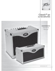
A. Front Panel<br />
1 2 3 4 5 6<br />
Figure 1<br />
3
1. Antenna Input Connector A<br />
2. Power Switch and Indicator:<br />
When the switch is turned on the red indicator<br />
illuminates to denote normal power status.<br />
3. RF Signal Level Indicator:<br />
Indicates the RF signal strength received from the<br />
microphone. As soon as the signal is emitted from<br />
the microphone the LED indicator illuminates.<br />
4. Audio Signal Level Indicator:<br />
Indicates the audio signal level. As soon as the<br />
microphone signal is modulated, the LED indicator<br />
illuminates.<br />
5. Volume Control:<br />
Adjusts the AF output level of the receiver.<br />
6. Antenna Input Connector B<br />
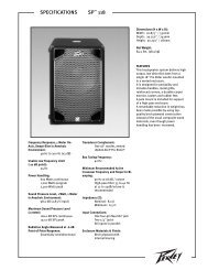
B. Rear Panel<br />
7 8 9 10 11<br />
Figure 2<br />
4
7. DC 12V Input Jack:<br />
Connect the 12V DC plug from the AC/DC adapter.<br />
8. Balanced Audio Output Jack:<br />
XLR type connector<br />
9. Unbalanced Audio Output Jack:<br />
1/4" Phone Jack<br />
10. Unbalanced Level Switch:<br />
“LOW selection is for “Microphone-Level” output.<br />
“HIGH” selection is for “Line-Out” level output.<br />
11. Squelch Adjustment:<br />
Adjust the squelch level to eliminate the RF noise<br />
interference at the receiver.<br />
2. INSTALLATION OF THE RECEIVER<br />
1. Install one of the antennas at the antenna input<br />
connector A. Then install the other antenna at<br />
the antenna input connector B.<br />
2. AC/DC Power Connection:<br />
Figure 3<br />
Connect the AC/DC adapter cable to the DC 12V<br />
input jack. Then plug the adapter unit into an<br />
appropriate AC outlet as shown in Figure 3. Caution:<br />
Make sure the correct voltage is present at the AC<br />
outlet as indicated on the AC/DC adapter.<br />
5
3. Audio Output Connection:<br />
a. Unbalanced Level Switch Setting Position:<br />
Make sure to match the unbalanced output<br />
setting to the device input setting. The<br />
incorrect setting could result in low sensitivity<br />
level or over load distortion. Ex. (If you are<br />
going into the “Line” input on a mixer or<br />
amplifier then the switch should be set to the<br />
high position. If you are going into the “Mic”<br />
input of an amplifier or mixer then the switch<br />
should be set to the low position.)<br />
b. Unbalanced Output:<br />
Connect the 1/4" phone plug of the audio cable<br />
into the unbalanced output connector on the<br />
back of the receiver. Connect the other end of<br />
the cable to the proper input of the desired<br />
device. Make sure the unbalanced level switch<br />
is in the proper position before applying power.<br />
c. Balanced Output:<br />
Connect the male XLR connector into the<br />
balanced output connector on the back of the<br />
receiver. Connect the other end of the cable<br />
into the “Mic/Balanced” input of the desired<br />
device. The characteristics of the 3-pin XLR<br />
connector are shown below in Figure 4.<br />
GND PIN 1<br />
PIN 2<br />
PIN 3<br />
Figure 4<br />
6
3. TWO 19/2-INCH UNITS RECEIVER INSTALLATION<br />
A. Setup for single half-rack receiver<br />
1. Push the rack mount brackets (RM-11)<br />
upwards until it is firmly attached to the<br />
receiver. (Figure 5)<br />
Figure 5<br />
B. Setup for dual half-rack receivers<br />
1. Remove the screws at the top and<br />
bottom of the receiver where they will<br />
be joined together. Remove one steel<br />
plate from each receiver. Push the<br />
receivers next to each other. Refer to<br />
Figure 6.<br />
2. Insert the steel plate in between the two<br />
receivers (top and bottom). Align and<br />
fasten the screws tightly as shown in<br />
Figure 6.<br />
3. Align and fasten the rack mount<br />
7
ackets (RM-12) on the outer sides of<br />
both receivers as shown in Figure 6.<br />
Figure 6<br />
4. After <strong>com</strong>pletion, it can be rackmounted<br />
into an EIA standard rack case. Shown<br />
in Figure 7.<br />
5. Make sure that the system performs<br />
correctly by placing the system away<br />
from noise sources. Place the receiver<br />
at least one meter above the ground<br />
and one meter away from noise<br />
sources. Place the microphone at least<br />
one meter away from the receiving<br />
antenna, as shown in Figure 8.<br />
Figure 7 Figure 8<br />
8
4. OPERATION INSTRUCTIONS<br />
1. Turn the volume controls of the receiver and<br />
device in use to a minimum setting before<br />
turning on the microphone transmitter. After<br />
the receivers power switch is set to the on<br />
position, the power switch’s red indicator<br />
illuminates to denote normal power status.<br />
2. If the SIGNAL LED indicators of the receiver<br />
are illuminated before switching on the<br />
microphone or transmitter, it indicates the<br />
receiver is receiving interference signals. The<br />
more LEDs that illuminate the more severity of<br />
interference. This system has “Pilotone” and<br />
“NoiseLock” dual-squelch features so noise<br />
output will not occur. If multiple channels are<br />
used and both SIGNAL and AUDIO LEDs<br />
illuminate before the transmitter is turned on,<br />
simply adjust the Squelch controls clockwise<br />
until the AUDIO signal indicators extinguish.<br />
(Figure 9). However, by adjusting the<br />
squelch controls it affects the sensitivity level<br />
of the receiver, therefore, shortening the<br />
operating distance and decreasing the<br />
stability.<br />
Figure 9<br />
3. Under normal circumstances, the SIGNAL<br />
indicator lights up when a microphone or<br />
transmitter is turned on near the receiver to<br />
indicate the receiver is ready for normal<br />
operation. Once sounds enter into the<br />
9
microphone the AUDIO LED indicators will<br />
illuminate according to the strength of sound<br />
level. If the LEDs do not illuminate or sound is<br />
not present at the output, the system is not<br />
functioning properly and must be checked.<br />
4. Receiver and Amplifier Volume Adjustment:<br />
a. Single-channel Unbalanced Audio<br />
Output: Switch the level switch on the<br />
rear panel of the receiver to the left<br />
“LOW” Position, then adjust the volume<br />
control to twelve o’clock position.<br />
Adjust the volume control of the<br />
amplifier or mixer to an appropriate<br />
sound level. The volume control is used<br />
for fine adjustment of the microphone<br />
sensitivity. When the knob is turned to<br />
the twelve o’clock position the output<br />
sensitivity level of the wireless<br />
microphone is the same as a normal<br />
dynamic microphone. Once the receiver<br />
output level is appropriately adjusted,<br />
do not adjust the volume control again.<br />
Adjust the mixer or amplifier volume<br />
control if the sound level needs to<br />
increase or decrease.<br />
b. Balanced Output: Adjust according to<br />
the unbalanced audio output method in<br />
the previous step. (Note: The level<br />
switch does not effect the balanced<br />
output.)<br />
c. To obtain the same sensitivity level<br />
when using a wireless microphone and<br />
a wired microphone with one amplifier<br />
or mixer connect both the receiver<br />
output and the wired output to a “MIC-<br />
10
IN” input jack of the amplifier or mixer.<br />
Adjust the volume controls of the<br />
amplifier or mixer to the same desired<br />
level, then properly fine adjust the<br />
receiver volume control to match the<br />
same sensitivity as the wired<br />
microphone.<br />
d. If the receiver output level is adjusted to<br />
a level that is near the maximum input<br />
level of the desired device, it will cause<br />
saturation distortion of the device when<br />
the receiver output level is increased<br />
due to a increase in level by the sound<br />
source. Conversely, S/N ratio will<br />
decrease if the receiver volume control<br />
is adjusted too low.<br />
5. Plug the cable of the mains unit into DC<br />
socket on the receiver’s back panel. Thread<br />
the cable through the cable grip as shown in<br />
the figure below (Figure 10). The cable<br />
grip prevents the connector from being pulled<br />
off by accident.<br />
Figure 10<br />
11
5. Caution<br />
1. Since the installation of the antenna<br />
influences the operating efficiency of<br />
the receiver, the most important rule is<br />
to minimize the distance as much as<br />
possible between the receiving antenna<br />
and the microphone for the best<br />
reception and performance.<br />
2. The output voltage of the external DC<br />
power supply should not be below 12V,<br />
otherwise it will not work properly. If the<br />
voltage is over 15V some <strong>com</strong>ponents<br />
of the receiver will be damaged due to<br />
excessive current draw. Use a power<br />
supply with a 1A minimum rating.<br />
12
HANDHELD WIRELESS MICROPHONE<br />
The <strong>Peavey</strong> Pro Comm <strong>PCX</strong>-<strong>U12</strong> handheld wireless<br />
microphone is a modular design. It also incorporates<br />
“Superior frequency tracking and muting techniques” dualsquelch<br />
to eliminate noise interference.<br />
1. Unit Features and Functions<br />
1. Grille: Protects cartridge and<br />
prevents breathing and wind<br />
POP noises.<br />
2. Housing: Upper portion that is<br />
connected to the capsule<br />
module. Internally it holds the<br />
transmitter PCB and battery<br />
<strong>com</strong>partment.<br />
3. Battery Status Indicator:<br />
Indicates the power on/off and<br />
battery status. When the<br />
power switch is turned ON,<br />
the red LED indicator flashes<br />
briefly and then go out,<br />
indicating normal battery<br />
status. If no flash occurs, it has<br />
either no battery or the battery<br />
is drained or installed<br />
incorrectly. The power led will<br />
also warn when the battery is<br />
weak by remaining on after<br />
power up. A battery<br />
replacement is then necessary.<br />
4. Power On-off Switch: Slide<br />
Figure 11<br />
the power switch to the “ON”<br />
position for use or to the “OFF” position when<br />
not in use.<br />
5. Battery Compartment:<br />
Designed to ac<strong>com</strong>modate one 9V battery.<br />
1<br />
2<br />
3<br />
4<br />
6 5<br />
13
6. Battery Cap: Covers battery in the battery<br />
<strong>com</strong>partment.<br />
2. BATTERY INSERTION<br />
Figure 12<br />
1. Unscrew the battery cap in a counterclockwise<br />
direction.<br />
2. Insert a 9V battery into the battery<br />
<strong>com</strong>partment according to the correct polarity<br />
as shown in Figure12. The moment the<br />
battery touches the terminals of the<br />
<strong>com</strong>partment, the indicator will flash briefly.<br />
This means the polarity is correct. However, if<br />
no flash occurs, this indicates wrong insertion<br />
or battery is dead. Please re-insert the battery<br />
according to its correct polarity or exchange it<br />
for a fresh battery.<br />
3. OPERATING INSTRUCTIONS<br />
1. When the microphone is switched on the<br />
indicator will flash briefly indicating normal<br />
operation.<br />
2. After the microphone is switched on the RF<br />
SIGNAL LED indicator of the receiver<br />
illuminates. As the signal strength increases<br />
the number of illuminated LEDs will increase.<br />
If only the red LED illuminates this indicates<br />
abnormal receiving status.<br />
3. During usage the AUDIO LED indicator of the<br />
receiver will illuminate according to the sound<br />
strength input to the microphone. When the<br />
14
ed LED is illuminated, it denotes the<br />
maximum sound pressure level is being<br />
reached but does not represent distortion.<br />
4. When the microphone is not in use make sure<br />
to turn it off to extend the battery life. Remove<br />
the battery from the battery <strong>com</strong>partment if the<br />
microphone will not be in use for a long period<br />
of time. If a rechargeable battery is used take<br />
it out for a recharge as necessary.<br />
BELT PACK TRANSMITTER<br />
1. Unit Features and Functions<br />
1. 4-pin Jack<br />
Input Connector: 1<br />
2<br />
Connects to the<br />
<strong>Peavey</strong> Pro<br />
Comm 4-pin<br />
3<br />
connector. Allow<br />
5 different input<br />
4<br />
configurations<br />
(See the five<br />
5<br />
ways of<br />
7<br />
connection on<br />
an AF input<br />
connection,<br />
6<br />
page 19.)<br />
2. Transmitting<br />
Antenna: 1/4<br />
Figure 11<br />
wavelength transmitting antenna<br />
3. GT/MT Switch: Switch to the GT position for<br />
electric guitar use ONLY. Gain Control is irrelevant<br />
for “GT” mode. Switch to the “MT” position for<br />
condenser microphone, wired microphone or Line-in<br />
use. Gain Control works in the “MT” mode for input<br />
sensitivity adjustments.<br />
15
4. Gain Control: Adjusts the input gain to an<br />
appropriate level.<br />
5. Transmitter Housing: Contains the PCB and<br />
battery.<br />
6. Battery Status Indicator: Indicates the power<br />
on/off and battery status.<br />
a. When the power switch is turned on the<br />
LED indicator flashes briefly, indicating<br />
normal battery status.<br />
b. If the LED illumination is sustained at<br />
either power on or during usage the<br />
battery level is low. The old battery should<br />
be replaced with a new one.<br />
7. Power Switch: Switch to ON position for<br />
operation. Switch to OFF position when not in<br />
use.<br />
8. Battery Compartment and Cover:<br />
Ac<strong>com</strong>modates one 9V battery. (Figure 14)<br />
2. OPERATING INSTRUCTIONS<br />
8<br />
Figure 14<br />
16
1. Push down on the battery cover to open the<br />
battery <strong>com</strong>partment.<br />
2. Insert a 9V battery into the battery<br />
<strong>com</strong>partment according to the correct polarity<br />
as shown in Figure 14. Then push up on the<br />
battery cover to close the battery <strong>com</strong>partment.<br />
3. The LED indicator will flash briefly when<br />
power is turned on to indicate normal battery<br />
status. If no flash occurs it has either no<br />
battery, the battery is drained or installed<br />
incorrectly. Change accordingly.<br />
4. 4-Pin Jack: Volume can be adjusted by the<br />
gain control. Gain control has no effect when<br />
the switch is in the “GT” position (Guitar).<br />
5. 4-Pin Jack: Align and insert the 4-pin plug into<br />
the jack accordingly and tighten it in the<br />
clockwise direction as shown in Figure 15.<br />
Figure15<br />
17
3. AF 4-PIN INPUT CONNECTION METHODS<br />
1. 2-Wire Electret condenser microphone Capsule<br />
2. 3-Wire Electret condenser microphone Capsule<br />
3. Dynamic Microphone<br />
4. Electric Guitar<br />
5. Line-in (Impedance 8 KΩAttenuated 10 dB)<br />
18
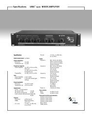
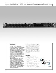
SPECIFICATIONS<br />
1. Overall: UHF <strong>PCX</strong>-<strong>U12</strong><br />
1. Carrier Frequency Range: UHF Band 790~960 MHz<br />
2. Oscillation Mode: Quartz-controlled<br />
3. Channel: 1-channel fixed<br />
4. Stability: ± 0.005 % with temperature <strong>com</strong>pensation<br />
5. Max. Deviation: ± 56 KHz with level limiting<br />
6. Dynamic Range: > 110 dB<br />
7. S/N Ratio: > 100 dB<br />
8. T.H.D.: < 0.5 %<br />
9. Squelch: “Superior frequency tracking and muting<br />
techniques” Dual-Squelch Circuitry<br />
10. Frequency Response: 60 Hz~18 KHz ±3 dB<br />
2. Receiver: UHF <strong>PCX</strong>-<strong>U12</strong><br />
1. Receiving Method: True Diversity Single<br />
Channel<br />
2. Sensitivity: 6 dBuV at S/N > 70 dB<br />
3. Image Rejection: > 60 dB<br />
4. Spurious Rejection: > 80 dB<br />
5. Audio Output: can switch between<br />
-2 dB/5 K Ω and -12 dB/600 Ω unbalanced<br />
and balanced<br />
6. Power Supply: 12~15 VDC/0.5 A<br />
7. Panel: 19/2-inch, half-rack size<br />
8. Dimensions (m/m): 210 (L) x 175 (W) x 44 (H)<br />
9. Weight: Approx. 1.0 Kgs<br />
3. Transmitter: UHF <strong>PCX</strong>-<strong>U12</strong><br />
1. Mic Element: Condenser Microphone Capsule<br />
2. Antenna: Built-in<br />
3. RF Output: 10~50 mW (according to regulation)<br />
4. Spurious: < -40 dBc<br />
5. Battery: One 9-Volt Battery<br />
6. Dimensions: (m/m): 49 x 234(L)<br />
7. Weight: 270 grams (without battery)<br />
8. 20-hour battery life per single 9-volt alkaline<br />
19
TROUBLESHOOTING GUIDE<br />
Symptom Distance Possible Possible<br />
Cause Solution<br />
No AF signal Any low transmitter replace battery<br />
and no RF signal<br />
battery voltage<br />
No AF signal long out of range move transmitter<br />
and no RF signal<br />
closer to receiver or<br />
obstecles<br />
No AF signal any microphone or check input source<br />
but normal RF signal<br />
other input source<br />
Distortion with no any low transmitter replace battery<br />
AF peak indication<br />
battery voltage<br />
Noise with low AF any strong RFI identify source and<br />
signal and normal<br />
eliminate, or change<br />
RF signal<br />
frequency of wireless<br />
microphone system<br />
Intermittent AF signal long out of range move transmitter and<br />
low RF signal<br />
closer to RCV<br />
Intermittent AF and average obstructions remove obstructions<br />
RF signals in signal path or reposition transmitter<br />
and/or RCV<br />
MULITPLE SYSTEM<br />
Symptom Distance Possible Action<br />
Cause<br />
Distortion on two any units on same change frequencies<br />
or more systems without<br />
frequency<br />
Distortion on one transmitter- transmitter + transmitter change frequencies<br />
or more systems without transmitter short intermod<br />
Distortion on one transmitter- transmitter + transmitter increase transmitter<br />
or more systems without transmitter short intermod to transmitter distance<br />
transmitter-receiver transmitter +transmitter change frequencies<br />
short<br />
receiver intermod<br />
Distortion on one or more transmitter-receiver transmitter +transmitter increase transmitter<br />
systems without short receiver intermod to receive distance<br />
AF peak indication<br />
20
NOTES:<br />
21
PEAVEY ELECTRONICS CORPORATION LIMITED WARRANTY<br />
Effective Date: July 1, 1998<br />
What This Warranty Covers<br />
Your <strong>Peavey</strong> Warranty covers defects in material and workmanship in <strong>Peavey</strong> products purchased and serviced in the<br />
U.S.A. and Canada.<br />
What This Warranty Does Not Cover<br />
The Warranty does not cover: (1) damage caused by accident, misuse, abuse, improper installation or operation, rental,<br />
product modification or neglect; (2) damage occurring during shipment; (3) damage caused by repair or service performed<br />
by persons not authorized by <strong>Peavey</strong>; (4) products on which the serial number has been altered, defaced or<br />
removed; (5) products not purchased from an Authorized <strong>Peavey</strong> Dealer.<br />
Who This Warranty Protects<br />
This Warranty protects only the original retail purchaser of the product.<br />
How Long This Warranty Lasts<br />
The Warranty begins on the date of purchase by the original retail purchaser. The duration of the Warranty is as follows:<br />
Product Category<br />
Guitars/Basses, Amplifiers, Pre-Amplifiers, Mixers, Electronic<br />
Crossovers and Equalizers<br />
Drums<br />
Enclosures<br />
Digital Effect Devices and Keyboard and MIDI Controllers<br />
Microphones<br />
Speaker Components (incl. speakers, baskets, drivers,<br />
diaphragm replacement kits and passive crossovers)<br />
and all Accessories<br />
Tubes and Meters<br />
Duration<br />
2 years *(+ 3 years)<br />
2 years *(+ 1 year)<br />
3 years *(+ 2 years)<br />
1 year *(+ 1 year)<br />
2 years<br />
1 year<br />
90 days<br />
[*denotes additional warranty period applicable if optional Warranty Registration Card is <strong>com</strong>pleted and<br />
returned to <strong>Peavey</strong> by original retail purchaser within 90 days of purchase.]<br />
What <strong>Peavey</strong> Will Do<br />
We will repair or replace (at <strong>Peavey</strong>'s discretion) products covered by warranty at no charge for labor or materials. If<br />
the product or <strong>com</strong>ponent must be shipped to <strong>Peavey</strong> for warranty service, the consumer must pay initial shipping<br />
charges. If the repairs are covered by warranty, <strong>Peavey</strong> will pay the return shipping charges.<br />
How To Get Warranty Service<br />
(1) Take the defective item and your sales receipt or other proof of date of purchase to your Authorized <strong>Peavey</strong><br />
Dealer or Authorized <strong>Peavey</strong> Service Center.<br />
OR<br />
(2) Ship the defective item, prepaid, to <strong>Peavey</strong> Electronics Corporation, International Service Center, 412 Highway 11 &<br />
80 East, Meridian, MS 39301 or <strong>Peavey</strong> Canada Ltd., 95 Shields Court, Markham, Ontario, Canada L3R 9T5. Include a<br />
detailed description of the problem, together with a copy of your sales receipt or other proof of date of purchase as evidence<br />
of warranty coverage. Also provide a <strong>com</strong>plete return address.<br />
Limitation of Implied Warranties<br />
ANY IMPLIED WARRANTIES, INCLUDING WARRANTIES OF MERCHANTABILITY AND FITNESS FOR A PARTICU-<br />
LAR PURPOSE, ARE LIMITED IN DURATION TO THE LENGTH OF THIS WARRANTY.<br />
Some states do not allow limitations on how long an implied warranty lasts, so the above limitation may not<br />
apply to you.<br />
Exclusions of Damages<br />
PEAVEY'S LIABILITY FOR ANY DEFECTIVE PRODUCT IS LIMITED TO THE REPAIR OR REPLACEMENT OF THE<br />
PRODUCT, AT PEAVEY'S OPTION. IF WE ELECT TO REPLACE THE PRODUCT, THE REPLACEMENT MAY BE A<br />
RECONDITIONED UNIT. PEAVEY SHALL NOT BE LIABLE FOR DAMAGES BASED ON INCONVENIENCE, LOSS<br />
OF USE, LOST PROFITS, LOST SAVINGS, DAMAGE TO ANY OTHER EQUIPMENT OR OTHER ITEMS AT THE SITE<br />
OF USE, OR ANY OTHER DAMAGES WHETHER INCIDENTAL, CONSEQUENTIAL OR OTHERWISE, EVEN IF<br />
PEAVEY HAS BEEN ADVISED OF THE POSSIBILITY OF SUCH DAMAGES.<br />
Some states do not allow the exclusion or limitation of incidental or consequential damages, so the above limitation<br />
or exclusion may not apply to you.<br />
This Warranty gives you specific legal rights, and you may also have other rights which vary from state to<br />
state.<br />
If you have any questions about this warranty or service received or if you need assistance in locating an Authorized<br />
Service Center, please contact the <strong>Peavey</strong> International Service Center at (601) 483-5365 / <strong>Peavey</strong> Canada Ltd. at<br />
(905) 475-2578.<br />
Features and specifications subject to change without notice.<br />
22
IMPORTANT SAFETY INSTRUCTIONS<br />
WARNING: When using electric products, basic cautions should always be followed, including the following:<br />
1. Read these instructions.<br />
2. Keep these instructions.<br />
3. Heed all warnings.<br />
4. Follow all instructions.<br />
5. Do not use this apparatus near water. For example, near or in a bathtub, swimming pool, sink, wet basement, etc.<br />
6. Clean only with a damp cloth.<br />
7. Do not block any of the ventilation openings. Install in accordance with manufacturer’s instructions. It should not be placed flat against a<br />
wall or placed in a built-in enclosure that will impede the flow of cooling air.<br />
8. Do not install near any heat sources such as radiators, heat registers, stoves or other apparatus (including amplifiers) that produce heat.<br />
9. Do not defeat the safety purpose of the polarized or grounding-type plug. A polarized plug has two blades with one wider than the other. A<br />
grounding type plug has two blades and a third grounding plug. The wide blade or third prong is provided for your safety. When the provided<br />
plug does not fit into your inlet, consult an electrician for replacement of the obsolete outlet. Never break off the grounding. Write<br />
for our free booklet “Shock Hazard and Grounding”. Connect only to a power supply of the type marked on the unit adjacent to the power<br />
supply cord.<br />
10. Protect the power cord from being walked on or pinched, particularly at plugs, convenience receptacles, and the point they exit from the<br />
apparatus.<br />
11. Only use attachments/accessories provided by the manufacturer.<br />
12. Use only with a cart, stand, tripod, bracket, or table specified by the manufacturer, or sold with the apparatus. When a cart is used, use caution<br />
when moving the cart/apparatus <strong>com</strong>bination to avoid injury from tip-over.<br />
13. Unplug this apparatus during lightning storms or when unused for long periods of time.<br />
14. Refer all servicing to qualified service personnel. Servicing is required when the apparatus has been damaged in any way, such as powersupply<br />
cord or plug is damaged, liquid has been spilled or objects have fallen into the apparatus, the apparatus has been exposed to rain or<br />
moisture, does not operate normally, or has been dropped.<br />
15. If this product is to be mounted in an equipment rack, rear support should be provided.<br />
16. Exposure to extremely high noise levels may cause a permanent hearing loss. Individuals vary considerably in susceptibility to noise-induced<br />
hearing loss, but nearly everyone will lose some hearing if exposed to sufficiently intense noise for a sufficient time. The U.S. Government’s<br />
Occupational and Health Administration (OSHA) has specified the following permissible noise level exposures:<br />
Duration Per Day In Hours<br />
Sound Level dBA, Slow Response<br />
8 90<br />
6 92<br />
4 95<br />
3 97<br />
2 100<br />
1 1/2 102<br />
1 105<br />
1/2 110<br />
1/4 or less 115<br />
According to OSHA, any exposure in excess of the above permissible limits could result in some hearing loss. Ear plugs or protectors to the ear<br />
canals or over the ears must be worn when operating this amplification system in order to prevent a permanent hearing loss, if exposure is in excess<br />
of the limits as set forth above. To ensure against potentially dangerous exposure to high sound pressure levels, it is re<strong>com</strong>mended that all persons<br />
exposed to equipment capable of producing high sound pressure levels such as this amplification system be protected by hearing protectors while<br />
this unit is in operation.<br />
SAVE THESE INSTRUCTIONS!<br />
23
Features and specifications subject to change without notice.<br />
<strong>Peavey</strong> Electronics Corporations • 711 A Street • Meridian<br />
MS • 39301 • (601) 483-5365 • Fax 486-1278<br />
©2000