You also want an ePaper? Increase the reach of your titles
YUMPU automatically turns print PDFs into web optimized ePapers that Google loves.
<strong>ICA</strong> <br />
SERIES<br />
INDUSTRIAL CONTRACTOR AMPLIFIERS<br />
OPERATING GUIDE
Intended to alert the user to the presence of uninsulated “dangerous voltage” within the product’s<br />
enclosure that may be of sufficient magnitude to constitute a risk of electric shock to persons.<br />
Intended to alert the user of the presence of important operating and maintenance (servicing)<br />
instructions in the literature acc<strong>om</strong>panying the product.<br />
CAUTION: Risk of electrical shock — DO NOT OPEN!<br />
CAUTION: To reduce the risk of electric shock, do not remove cover. No user serviceable parts inside. Refer<br />
servicing to qualified service personnel.<br />
WARNING: To prevent electrical shock or fire hazard, do not expose this appliance to rain or moisture. Before<br />
using this appliance, read the operating guide for further warnings.<br />
Este símbolo tiene el propósito, de alertar al usuario de la presencia de “(voltaje) peligroso” sin aislamiento<br />
dentro de la caja del producto y que puede tener una magnitud suficiente c<strong>om</strong>o para constituir<br />
riesgo de descarga eléctrica.<br />
Este símbolo tiene el propósito de alertar al usario de la presencia de instruccones importantes sobre la<br />
operación y mantenimiento en la información que viene con el producto.<br />
PRECAUCION: Riesgo de descarga eléctrica ¡NO ABRIR!<br />
PRECAUCION: Para disminuír el riesgo de descarga eléctrica, no abra la cubierta. No hay piezas útiles dentro.<br />
Deje todo mantenimiento en manos del personal técnico cualificado.<br />
ADVERTENCIA: Para evitar descargas eléctricas o peligro de incendio, no deje expuesto a la lluvia o humedad<br />
este aparato Antes de usar este aparato, Iea más advertencias en la guía de operación.<br />
Ce symbole est utilisé dans ce manuel pour indiquer à l’utilisateur la présence d’une tension dangereuse<br />
pouvant être d’amplitude suffisante pour constituer un risque de choc électrique.<br />
Ce symbole est utilisé dans ce manuel pour indiquer à l’utilisateur qu’il ou qu’elle trouvera d’importantes<br />
instructions concernant l’utilisation et l’entretien de l’appareil dans le paragraphe signalé.<br />
ATTENTION: Risques de choc électrique — NE PAS OUVRIR!<br />
ATTENTION: Afin de réduire le risque de choc électrique, ne pas enlever le couvercle. Il ne se trouve à l’intérieur<br />
aucune pièce pouvant être reparée par l’utilisateur. Confiez I’entretien et la réparation de l’appareil à un réparateur<br />
<strong>Peavey</strong> agréé.<br />
AVERTISSEMENT: Afin de prévenir les risques de décharge électrique ou de feu, n’exposez pas cet appareil à la<br />
pluie ou à l’humidité. Avant d’utiliser cet appareil, lisez attentivement les avertissements supplémentaires de ce<br />
manuel.<br />
Dieses Symbol soll den Anwender vor unisolierten gefährlichen Spannungen innerhalb des Gehäuses<br />
warnen, die von Ausreichender Stärke sind, um einen elektrischen Schlag verursachen zu können.<br />
Dieses Symbol soll den Benutzer auf wichtige Instruktionen in der Bedienungsanleitung aufmerksam<br />
machen, die Handhabung und Wartung des Produkts betreffen.<br />
VORSICHT: Risiko — Elektrischer Schlag! Nicht öffnen!<br />
VORSICHT: Um das Risiko eines elektrischen Schlages zu vermeiden, nicht die Abdeckung enfernen. Es befinden<br />
sich keine Teile darin, die v<strong>om</strong> Anwender repariert werden könnten. Reparaturen nur von qualifiziertem<br />
Fachpersonal durchführen lassen.<br />
ACHTUNG: Um einen elektrischen Schlag oder Feuergefahr zu vermeiden, sollte dieses Gerät nicht dem Regen<br />
oder Feuchtigkeit ausgesetzt werden. Vor Inbetriebnahme unbedingt die Bedienungsanleitung lesen.<br />
2
TABLE OF CONTENTS<br />
Page<br />
INTRODUCTION . . . . . . . . . . . . . . . . . . . . . . . . . . . . . . . . . . . . . . . . . . . . . . . . . . . . 4<br />
UNPACKING . . . . . . . . . . . . . . . . . . . . . . . . . . . . . . . . . . . . . . . . . . . . . . . . . . . . . . . 4<br />
INSTALLATION AND MOUNTING . . . . . . . . . . . . . . . . . . . . . . . . . . . . . . . . . . . . . . . 4<br />
BASIC SETUP. . . . . . . . . . . . . . . . . . . . . . . . . . . . . . . . . . . . . . . . . . . . . . . . . . . . . . 4<br />
FRONT PANEL FEATURES. . . . . . . . . . . . . . . . . . . . . . . . . . . . . . . . . . . . . . . . . . . . 5<br />
BACK PANEL FEATURES . . . . . . . . . . . . . . . . . . . . . . . . . . . . . . . . . . . . . . . . . . . . . 6<br />
OPERATION . . . . . . . . . . . . . . . . . . . . . . . . . . . . . . . . . . . . . . . . . . . . . . . . . . . . . . . 7<br />
PROTECTION FEATURES . . . . . . . . . . . . . . . . . . . . . . . . . . . . . . . . . . . . . . . . . . . . 9<br />
SEQUENTIAL TURN-ON / TURN-OFF. . . . . . . . . . . . . . . . . . . . . . . . . . . . . . . . . . . . 10<br />
WIRE GAUGE CHART . . . . . . . . . . . . . . . . . . . . . . . . . . . . . . . . . . . . . . . . . . . . . . . 11<br />
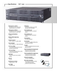
<strong>ICA</strong> 600 SPECIF<strong>ICA</strong>TIONS . . . . . . . . . . . . . . . . . . . . . . . . . . . . . . . . . . . . . . . . . . . 12<br />
<strong>ICA</strong> 1200 SPECIF<strong>ICA</strong>TIONS . . . . . . . . . . . . . . . . . . . . . . . . . . . . . . . . . . . . . . . . . . 13<br />
<strong>ICA</strong> 2400 SPECIF<strong>ICA</strong>TIONS . . . . . . . . . . . . . . . . . . . . . . . . . . . . . . . . . . . . . . . . . . 14<br />
<strong>ICA</strong> 400V SPECIF<strong>ICA</strong>TIONS . . . . . . . . . . . . . . . . . . . . . . . . . . . . . . . . . . . . . . . . . . 15<br />
<strong>ICA</strong> 800V SPECIF<strong>ICA</strong>TIONS . . . . . . . . . . . . . . . . . . . . . . . . . . . . . . . . . . . . . . . . . . 16<br />
<strong>ICA</strong> 2400V SPECIF<strong>ICA</strong>TIONS . . . . . . . . . . . . . . . . . . . . . . . . . . . . . . . . . . . . . . . . . 17<br />
IMPORTANT SAFETY INSTRUCTIONS. . . . . . . . . . . . . . . . . . . . . . . . . . . . . . . . . . . 18<br />
WARRANTY INFORMATION . . . . . . . . . . . . . . . . . . . . . . . . . . . . . . . . . . . . . . . . . . . 19<br />
3
INTRODUCTION<br />
Congratulations on your purchase of an Architectural Acoustics <strong>ICA</strong> (Industrial Contractor Amplifier)<br />
fr<strong>om</strong> <strong>Peavey</strong> Electronics. Please read this manual carefully, especially the IMPORTANT SAFETY<br />
INSTRUCTIONS on page 18. It contains information vital to safe operation of the power amplifier.<br />
Also, please fill out and return the enclosed product registration card.<br />
<strong>ICA</strong> Series amplifiers represent new levels of value and flexibility never before offered to the<br />
contracting market. The <strong>ICA</strong> Series features models specifically designed to drive 4-ohm outputs,<br />
70.7-volt outputs, and 100-volt outputs. 70.7 and 100-volt outputs can be driven directly, eliminating<br />
the need for transformers or autoformers. These amplifiers cover almost every installed or<br />
distributed sound power requirement imaginable.<br />
<strong>ICA</strong> Series amplifiers are ruggedly built fr<strong>om</strong> high-quality c<strong>om</strong>ponents and feature c<strong>om</strong>prehensive<br />
protection circuits to protect your amplifier fr<strong>om</strong> those “real world” occurrences.<br />
If you need setup or operational assistance for this product, please call the <strong>Peavey</strong> Electronics<br />
Cust<strong>om</strong>er Service Department or your local <strong>Peavey</strong> Electronics representative. We appreciate<br />
suggestions that may help us improve our products and/or service.<br />
UNPACKING<br />
Inspect the amplifier during unpacking. If you find any damage, notify your dealer immediately.<br />
Only the consignee may institute a claim with the carrier for damage incurred during shipping. Be<br />
sure to save the carton and all packing materials. Should you ever need to ship the unit back to<br />
<strong>Peavey</strong> Electronics, one of its service centers, or the dealer; use only the original factory packing.<br />
INSTALLATION AND MOUNTING<br />
<strong>ICA</strong> Series amplifiers are 2 or 3-rack-space units of 15 3/4" (400 mm) depth that mount in a<br />
standard 19" rack. On all amplifiers, front panel mounting holes are provided.<br />
BASIC SETUP<br />
ENGLISH<br />
1. Rack mount the amplifier in the location where it is to be used, remembering to allow for<br />
adequate access and cooling space. For more information, see the sections on<br />
INSTALLATION AND MOUNTING and COOLING REQUIREMENTS.<br />
2. Make input connections to the plugable terminal blocks on the rear panel. Use the proper<br />
connections for stereo, parallel, bridged mono, and grounding configuration. See the sections<br />
on SIGNAL MODE CONFIGURATION and INPUT MODULE CONNECTIONS for more<br />
information.<br />
3. Connect speakers to the output barrier strip. Be sure to make the correct output connections<br />
for stereo, parallel or bridged mono configuration. See the section on SPEAKER OUTPUT<br />
CONNECTIONS for more information.<br />
4. Make power connections, allowing for proper current draw. See the sections on IEC POWER<br />
CONNECTOR and AC MAINS CIRCUIT SIZE REQUIREMENTS for more information.<br />
5. Turn the front panel 3-position AC POWER switch to ON and bring up the back panel LEVEL<br />
(gain) attenuators to the desired levels.<br />
4
FRONT PANEL FEATURES<br />
600<br />
INDUSTRIAL<br />
CONTRACTOR<br />
AMPLIFIER<br />
TM<br />
A<br />
SIGNAL<br />
B<br />
CLIP<br />
TM LFC<br />
PROTECT<br />
POWER<br />
POWER<br />
STANDBY OFF ON<br />
RCHITECTURAL<br />
COUSTICS<br />
TM<br />
by<br />
4 5 6 7 3 2 1<br />
1. RACK MOUNTING EARS<br />
These mounting holes are provided on each front mounting ear.<br />
2. 3-POSITION AC POWER SWITCH<br />
A 3-position switch is on the front panel. Sequential remote turn-on capability is a standard<br />
feature. With the switch pushed towards the outside position, the amplifier is ON. The middle<br />
position is OFF, and the inside position is marked STANDBY. When switched to STANDBY,<br />
the amplifier may be activated by the sequential turn-on circuit. See the section on<br />
SEQUENTIAL TURN-ON / TURN-OFF for more information.<br />
3. POWER LED<br />
The POWER LED illuminates when the amplifier is turned on.<br />
4. SIGNAL LED<br />
Each channel has a SIGNAL LED that illuminates when the amplifier output exceeds 1 volt.<br />
5. CLIP LED<br />
Each channel has a CLIP LED that illuminates at the clipping point, and indicates that internal<br />
circuitry is reducing amplifier gain to allow full power. See the section on PROTECTION<br />
FEATURES for more information.<br />
6. LFC LED<br />
Each channel has a LFC (Load Fault Correction) LED. This LED illuminates when the<br />
amplifier channel detects an abnormal load condition. Internal circuitry will instantaneously<br />
reduce the channel gain to allow the amplifier to operate at a safe level into the abnormal<br />
load. See the section on PROTECTION FEATURES for more information.<br />
7. PROTECT LED<br />
If the amplifier has just been turned on or has detected a fault condition, the speaker output<br />
relays will open, illuminating this LED.<br />
5
BACK PANEL FEATURES<br />
10 11<br />
9<br />
12 13 8<br />
8. INPUT SECTION<br />
The <strong>ICA</strong> Series c<strong>om</strong>es standard with plugable input connectors and individual channel rotary<br />
attenuators. Connections at the input connector permit the audio signal ground to be<br />
connected or lifted fr<strong>om</strong> the chassis ground.<br />
9. OUTPUT BARRIER STRIP<br />
A barrier strip is provided for connection of loudspeakers with bare wire or spade lug<br />
connectors. This barrier strip can acc<strong>om</strong>modate up to two 10-gauge wires per terminal.<br />
10. IEC POWER CONNECTOR<br />
A standard IEC power connector is located at the upper left corner of the amplifier rear panel.<br />
An AC mains cord having an appropriate AC plug for the intended operating voltage is<br />
included.<br />
NOTE: FOR UK ONLY<br />
If the colors of the wires in the mains lead of this unit do not correspond with the colored<br />
markings identifying the terminals in your plug, proceed as follows: (1) The wire that is<br />
colored green and yellow must be connected to the terminal that is marked by the letter E,<br />
the earth symbol, colored green, or colored green and yellow. (2) The wire that is colored<br />
blue must be connected to the terminal that is marked with the letter N or the color black. (3).<br />
The wire that is colored brown must be connected to the terminal that is marked with the<br />
letter L or the color red.<br />
11. CIRCUIT BREAKER<br />
A resettable, protective AC circuit breaker is located at the upper left of the amplifier back<br />
panel. If the breaker has tripped, push it back in to return the amplifier to operating condition.<br />
If the breaker continues to trip, the amplifier needs servicing. Do not continue to reset the<br />
breaker because severe internal damage and safety hazards could occur!<br />
12. SEQUENTIAL TURN-ON CONNECTOR<br />
The <strong>ICA</strong> Series c<strong>om</strong>es standard with remote-controllable sequential turn on enabled by<br />
setting the front power switch to STANDBY. The amplifier is activated by applying a voltage<br />
between 12 to 24 volts DC to the rear-mounted, 4-pin plugable terminal, and connecting the<br />
ENABLE terminal to the 24 V DC+ terminal. When no voltage is present or the ENABLE<br />
connection is opened, the amplifier will switch off. Other <strong>ICA</strong> Series amplifiers can be “daisy<br />
chained” by connecting all 24 V DC+ terminals together, all COMMON terminals together, and<br />
6
connecting the ENABLE OUT to the ENABLE IN of the next amplifier. A mating connector is<br />
shipped with the amplifier.<br />
13. FAN GRILL<br />
A continuously variable-speed DC fan supplies cool air into the amplifier. Do not block this<br />
intake! The fan operates only when the amplifier heat sinks require cooling.<br />
OPERATION<br />
AC MAINS CIRCUIT SIZE REQUIREMENTS<br />
Power requirements for <strong>ICA</strong> amplifiers are rated at “idle”, 1/8 power (“typical” music<br />
conditions), 1/3 power, and maximum rated power. The maximum power current draw rating<br />
is limited by the amplifier’s circuit breaker. Consult the specification sheet for the current that each<br />
amplifier will demand. AC mains voltage must be the same as that indicated on the back of the<br />
amplifier. Damage caused by connecting the amplifier to improper AC voltage is not covered by any<br />
warranty. NOTE: Always turn off and disconnect the amplifier fr<strong>om</strong> the mains voltage before making<br />
audio connections. As an extra precaution, have the input attenuators turned down during initial<br />
power up.<br />
COOLING REQUIREMENTS<br />
<strong>ICA</strong> Series amplifiers use a forced-air cooling system to maintain a low, even operating<br />
temperature. Cooling air is drawn by a continuously variable-speed fan mounted on the back<br />
panel, and exhausts through slots on the front panel. The fan will remain inactive until internal<br />
operating temperature rises above 45º C (113º F). Make sure there is enough space around the<br />
back of the amplifier to allow air to enter. NOTE: If the amplifier is rack mounted, do not use doors<br />
or covers on the front or back without pressurizing the back of the rack. Whatever type of rack you<br />
are using, make sure that heated air can escape freely, and that there is no resistance to the intake<br />
of cool air through the back grill. Intake and exhaust air must flow without resistance.<br />
HIBERNATION <br />
All <strong>ICA</strong> Series amps feature Hibernation circuitry. Current draw and thermal emissions are at a<br />
minimum when the absence of input signal is sensed for more than a minute. Once signal is<br />
present, Hibernation instantly restores the amplifier to normal. Current draw specifications while<br />
Hibernation is active are included in specifications under Idle Current Draw.<br />
THERMAL EMISSIONS<br />
The system installer or designer should specify system cooling needs. Refer to the specifications at<br />
the back of this manual for specific thermal emissions figures.<br />
INPUT CONNECTIONS<br />
The input connector accepts balanced and unbalanced audio signals. For use with an unbalanced<br />
source, tie the inverting (-) input to ground by installing a jumper to the signal ground connection. If<br />
the inverting input is left floating, a 6 dB loss in gain will result.<br />
7
SIGNAL MODE CONFIGURATION<br />
<strong>ICA</strong> Series amplifiers are configured for Stereo (2-channel), Bridged Mode, or Parallel Mode<br />
operation at the input connector.<br />
To send the same signal to both channels (Parallel Mode), connect the input signal to CHANNEL A<br />
via the input connector. Run jumpers fr<strong>om</strong> the positive and negative terminals of the CHANNEL A<br />
input connector to the respective terminals of CHANNEL B. Both channels then share the<br />
CHANNEL A input signal but will operate independently. Speakers are connected as in Stereo Mode.<br />
Bridged Mode converts the amplifier into a single-channel unit with a power rating equal to the sum<br />
of both channel power ratings, and at a load rating twice that of the single-channel rating. In Bridged<br />
Mode, the channels operate at opposite polarity of each other so that one channel “pushes” and the<br />
other “pulls” equally. Signal is connected to the input connector with one jumper connecting the<br />
positive (+) terminal of Input A to the negative (-) terminal of Input B, and another jumper connecting<br />
the negative (-) terminal of Input A to the positive (+) terminal of Input B. Both channel attenuators<br />
(A & B) are used to control signal level, and both must be at the same level, preferably at 0 dB<br />
attenuation. The speakers are connected only to the designated “+” output terminals. NEVER<br />
ground either side of the speaker cable when the amplifier is in Bridged Mode as both sides<br />
are “hot”. If an output patch panel is used, all connections must be isolated fr<strong>om</strong> each other and<br />
fr<strong>om</strong> the panel. For <strong>ICA</strong> Series amplifiers, the minimum n<strong>om</strong>inal load impedance in Bridged Mode is<br />
8 ohms; this is the equivalent of driving both channels at 4 ohms. Driving loads of less than 8 ohms<br />
may activate the LFC circuit and may also cause a thermal protect condition. NOTE: Regardless of<br />
operating mode, NEVER connect amplifier outputs together!<br />
STEREO MODE CONNECTION DIAGRAM<br />
PARALLEL MODE DIAGRAM<br />
CAUTION<br />
120 VAC<br />
60 Hz<br />
700 WATTS<br />
WARNING: TO REDUCE THE RISK OF FIRE OR<br />
ELECTRIC SHOCK DO NOT EXPOSE THIS EQUIPMENT<br />
TO RAIN OR MOISTURE.<br />
AVIS: RISQUE DE CHOC ELECTRIQUE-NE PAS OUVRIR.<br />
MOUNT IN RACK ONLY<br />
INSTALLER SUR SUPPORT DE MONTAGE SEULEMENT<br />
OUTPUT B<br />
CLASS 2 WIRING<br />
OUTPUT POWER @ 4 OHMS IS 300 WATTS/CH<br />
ENABLE IN<br />
24V DC+<br />
A DIVISION OF PEAVEY ELECTRONICS CORP. MERIDIAN, MS MADE IN U.S.A.<br />
OUTPUT A<br />
ENABLE OUT<br />
COMMON<br />
TM<br />
600<br />
INDUSTRIAL CONTRACTOR AMPLIFIER<br />
-6 -6<br />
-10 -3<br />
-10 -3<br />
-15<br />
-15<br />
-1<br />
-1<br />
-30<br />
-30<br />
INPUT B<br />
-80 0<br />
-80 0<br />
LEVEL B<br />
LEVEL A<br />
(dB)<br />
(dB)<br />
RCHITECTURAL<br />
COUSTICS<br />
TM<br />
by<br />
INPUT A<br />
8
BRIDGED MODE DIAGRAM<br />
CAUTION<br />
120 VAC<br />
60 Hz<br />
700 WATTS<br />
WARNING: TO REDUCE THE RISK OF FIRE OR<br />
ELECTRIC SHOCK DO NOT EXPOSE THIS EQUIPMENT<br />
TO RAIN OR MOISTURE.<br />
AVIS: RISQUE DE CHOC ELECTRIQUE-NE PAS OUVRIR.<br />
MOUNT IN RACK ONLY<br />
INSTALLER SUR SUPPORT DE MONTAGE SEULEMENT<br />
OUTPUT B<br />
CLASS 2 WIRING<br />
OUTPUT POWER @ 4 OHMS IS 300 WATTS/CH<br />
ENABLE IN<br />
24V DC+<br />
A DIVISION OF PEAVEY ELECTRONICS CORP. MERIDIAN, MS MADE IN U.S.A.<br />
OUTPUT A<br />
ENABLE OUT<br />
COMMON<br />
TM<br />
600<br />
INDUSTRIAL CONTRACTOR AMPLIFIER<br />
-6 -6<br />
-10 -3<br />
-10 -3<br />
-15<br />
-15<br />
-1<br />
-1<br />
-30<br />
-30<br />
INPUT B<br />
-80 0<br />
-80 0<br />
LEVEL B<br />
LEVEL A<br />
(dB)<br />
(dB)<br />
RCHITECTURAL<br />
COUSTICS<br />
TM<br />
by<br />
INPUT A<br />
SPEAKER OUTPUT CONNECTIONS<br />
Speakers are connected using the output barrier strip connectors. Spade lugs, ring tongues or bare<br />
wire may be connected to the output barrier strip elements. The barrier strip can acc<strong>om</strong>modate up to<br />
two 10-guage wires per terminal. Make sure the amplifier is turned off before you change any output<br />
connections or jumpers. Consult the Wire Gauge Chart at the back of this manual to find a suitable<br />
wire gauge to minimize losses of power in the speaker cables. Also, make sure that the load<br />
impedance is not lower than that rated for the amplifier.<br />
SIGNAL GROUND CONNECTION<br />
Connections at the input connector permit the audio signal ground to be connected or lifted fr<strong>om</strong> the<br />
chassis ground. When possible, the shield of the signal source connecting cable should connect to<br />
the chassis ground. In s<strong>om</strong>e cases, however, particularly if an amplifier is being installed in an<br />
existing system, this may result in a ground loop. If this happens, connect the shield to the signal<br />
ground only. The chassis ground also connects to the AC ground internally. If the cable shield is<br />
connected to the signal ground only, it will be clamped to +/- 0.6 V above or below chassis/AC<br />
ground.<br />
PROTECTION FEATURES<br />
The <strong>ICA</strong> Series incorporates protection features derived fr<strong>om</strong> <strong>Peavey</strong>’s extensive experience with<br />
reliability. The amplifiers are ruggedly built fr<strong>om</strong> high-quality c<strong>om</strong>ponents and feature c<strong>om</strong>prehensive<br />
protection circuits to protect your amplifier fr<strong>om</strong> those “real world” occurrences.<br />
CLIP LIMITING<br />
At the amplifier’s full power, or clipping point, the channel gain will aut<strong>om</strong>atically be reduced,<br />
guarding the loudspeakers against damaging high power and continuous square waves that would<br />
otherwise be produced. This is indicated by illumination of the CLIP LED. Normal program transients<br />
will not trigger Clip Limiting, only steady or excessive clipping will. Operation is virtually transparent<br />
in use and full signal bandwidth is maintained.<br />
LOAD FAULT CORRECTION <br />
LFC is an innovative circuit that will instantaneously reduce channel gain to allow the amplifier to<br />
operate at a safe level into an abnormal load. LFC activation is indicated by illumination of the LFC<br />
LED. Moderate activation of LFC is inaudible in normal use. In addition, if extreme low impedance or<br />
a short circuit is encountered during high signal level conditions, the amplifier’s output relay will<br />
open.<br />
9
FADE-IN PROTECTION<br />
This feature operates every time the amplifier is turned on, or after a protect condition. During turn<br />
on, the amplifier goes into protect mode and leaves the speaker load disconnected until the amplifier<br />
determines that the operating status is normal. The Fade-In circuit attenuates the signal during the<br />
initial turn on or protect operation. After relay release, channel gain gradually increases to the<br />
attenuator setting to avoid unnecessary stress on the loudspeakers.<br />
THERMAL PROTECTION<br />
If the heatsink or power transformer reaches an abnormally high temperature, the amplifier will<br />
protect itself by disconnecting the speaker load until the amplifier returns to a normal temperature.<br />
During this time, the PROTECT LED will illuminate, and the cooling fan will operate at maximum<br />
speed.<br />
SHORT CIRCUIT<br />
If an output is shorted, the LFC , speaker relay and thermal circuits will aut<strong>om</strong>atically protect the<br />
amplifier. The LFC circuit senses the short circuit as an abnormal load condition and reduces the<br />
channel gain to a safe level for the load. In extreme or severe conditions, the speaker relays will<br />
disconnect the load and initiate a power-on start-up sequence.<br />
DC VOLTAGE PROTECTION<br />
If an amplifier channel detects DC voltage or subsonic signals at its output terminals, the speaker<br />
relay will immediately open to prevent loudspeaker damage. The PROTECT LED will illuminate as<br />
notification of this condition.<br />
SEQUENTIAL TURN-ON / TURN-OFF<br />
The <strong>ICA</strong> Series c<strong>om</strong>es standard with remote sequential turn-on. The amplifier front power switch is<br />
set to STANDBY. An external direct plug-in power supply unit providing a n<strong>om</strong>inal voltage between<br />
12 to 24 volts DC must be applied to the 4-pin plugable terminal on the rear panel. The ENABLE<br />
OUT is connected to the ENABLE IN of the next amplifier. <strong>ICA</strong> Series amplifiers are bussed or<br />
“daisy chained” together in parallel and connected to the DC supply by connecting all 24 V DC+<br />
terminals together and all COMMON terminals together. The first amplifier in the chain requires an<br />
SPST closure between its 24 V DC+ terminal and ENABLE OUT terminal to initiate the power turnon<br />
sequence and keep the amplifiers in the chain powered on.<br />
Sequential Turn-On / Turn-Off Wiring<br />
To enable In of<br />
next amplifier<br />
To c<strong>om</strong>mon of<br />
next amplifier<br />
To 24 VDC+<br />
of next amplifier<br />
CAUTION<br />
120 VAC<br />
60 Hz<br />
700 WATTS<br />
WARNING: TO REDUCE THE RISK OF FIRE OR<br />
ELECTRIC SHOCK DO NOT EXPOSE THIS EQUIPMENT<br />
TO RAIN OR MOISTURE.<br />
AVIS: RISQUE DE CHOC ELECTRIQUE-NE PAS OUVRIR.<br />
MOUNT IN RACK ONLY<br />
INSTALLER SUR SUPPORT DE MONTAGE SEULEMENT<br />
OUTPUT B<br />
CLASS 2 WIRING<br />
OUTPUT POWER @ 4 OHMS IS 300 WATTS/CH<br />
ENABLE IN<br />
24V DC+<br />
A DIVISION OF PEAVEY ELECTRONICS CORP. MERIDIAN, MS MADE IN U.S.A.<br />
OUTPUT A<br />
ENABLE OUT<br />
COMMON<br />
TM<br />
600<br />
INDUSTRIAL CONTRACTOR AMPLIFIER<br />
-6 -6<br />
-10 -3<br />
-10 -3<br />
-15<br />
-15<br />
-1<br />
-1<br />
-30<br />
-30<br />
INPUT B<br />
-80 0<br />
-80 0<br />
LEVEL B<br />
LEVEL A<br />
(dB)<br />
(dB)<br />
RCHITECTURAL<br />
COUSTICS<br />
TM<br />
by<br />
INPUT A<br />
Sequential Turn On/<br />
Turn-Off Wiring<br />
24 VDC+<br />
C<strong>om</strong>mon<br />
Turn-on switch<br />
10
WIRE GAUGE CHART<br />
Stranded Power Power Power<br />
Cable Wire Loss Loss Loss<br />
Length Gauge Into Into Into<br />
(Feet) (AWG) 8 ohms 4 ohms 2 ohms<br />
______________________________________________________<br />
5' 18 AWG .79% 1.58% 3.16%<br />
16 .5 1.0 2.0<br />
14 .31 .62 1.24<br />
12 .20 .40 .80<br />
10 .125 .25 .50<br />
10' 18 AWG 1.58% 3.16% 6.32%<br />
16 1.0 2.0 4.00<br />
14 .62 1.25 2.50<br />
12 .40 .80 1.6<br />
10 .25 .50 1.0<br />
40' 18 AWG 8.0% 12.6% 25.2%<br />
16 4.0 8.0 16.0<br />
14 2.5 5.0 10.0<br />
12 1.60 3.2 6.4<br />
10 1.0 2.0 4.0<br />
8 .625 1.25 2.50<br />
80' 16 AWG 8.0% 16.0% 32.0%<br />
14 5.0 10.0 20.0<br />
12 3.2 6.4 12.8<br />
10 2.0 4.0 8.0<br />
11
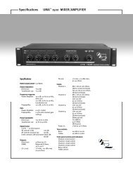
<strong>ICA</strong> 600 SPECIF<strong>ICA</strong>TIONS<br />
Rated Power (2 X 4 ohms):<br />
300 watts @ 20 Hz - 20 kHz, both<br />
channels driven at < 0.1% THD<br />
Rated Power (2 x 8 ohms):<br />
200 watts @ 20 Hz - 20 kHz at<br />
< 0.05% THD<br />
Rated Power (1 x 4 ohms):<br />
360 watts @ 1 kHz at < 0.015% THD<br />
Rated Power (1 x 8 ohms):<br />
275 watts @ 1 kHz at < 0.005%<br />
THD<br />
Minimum Load Impedance:<br />
4 ohms<br />
Maximum RMS Voltage Swing:<br />
57 volts<br />
Frequency Response:<br />
10 Hz - 25 kHz; +0, -3 dB at 1 watt<br />
Power Bandwidth:<br />
10 Hz - 100 kHz; +0, -3 dB at rated<br />
power<br />
THD (2 x 4 ohms):<br />
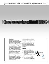
<strong>ICA</strong> 1200 SPECIF<strong>ICA</strong>TIONS<br />
Rated Power (2 X 4 ohms):<br />
600 watts @ 20 Hz - 20 kHz, both<br />
channels driven at < 0.1% THD<br />
Rated Power (2 X 8 ohms):<br />
400 watts @ 20 Hz - 20 kHz, both<br />
channels driven at < 0.05% THD<br />
Rated Power (1 X 4 ohms):<br />
700 watts @ 1 kHz at < 0.008% THD<br />
Rated Power (1 X 8 ohms):<br />
425 watts @ 1 kHz at < 0.005% THD<br />
Minimum Load Impedance:<br />
4 ohms<br />
Maximum RMS Voltage Swing:<br />
70 volts<br />
Frequency Response:<br />
10 Hz - 25 kHz; +0, -.3 dB at 1 watt<br />
Power Bandwidth:<br />
10 Hz - 100 kHz; +0, -3 dB at rated<br />
power<br />
THD (2 x 4 ohms):<br />
Rated Power (2 x 4 ohms):<br />
1200 watts @ 20 Hz - 20 kHz both<br />
channels driven at < 0.1% THD<br />
Rated Power (2 x 8 ohms):<br />
800 watts @ 20 Hz – 20 kHz both<br />
channels driven at < 0.08% THD<br />
Rated Power (1 x 4 ohms):<br />
1325 watts @ 1 kHz at < 0.08% THD<br />
Rated Power (1 x 8 ohms):<br />
830 watts @ 1 kHz at < 0.08% THD<br />
Topology:<br />
Class H<br />
Minimum Load Impedance:<br />
4 ohms<br />
Maximum RMS Voltage Swing:<br />
95 volts<br />
Frequency Response:<br />
10 Hz – 25 kHz; +0, -.3 dB at 1 watt<br />
Power Bandwidth:<br />
10 Hz – 50 kHz; +0, -3 dB at rated<br />
power<br />
THD (2 x 4 ohms):<br />
<strong>ICA</strong> 400V SPECIF<strong>ICA</strong>TIONS<br />
Rated Power (two channels):<br />
200 watts @ 20 Hz - 20 kHz both<br />
channels driven at
<strong>ICA</strong> 800V SPECIF<strong>ICA</strong>TIONS<br />
Rated Power (two channels):<br />
400 watts @ 20 Hz - 20 kHz both<br />
channels driven at < 0.1% THD<br />
Rated Power (one channel):<br />
415 watts @ 1 kHz at < 0.01% THD<br />
Minimum Load Impedance:<br />
<strong>ICA</strong> 800V-70: 12.5 ohms<br />
<strong>ICA</strong> 800V-100: 25 ohms<br />
Maximum RMS Voltage Swing:<br />
<strong>ICA</strong> 800V-70: 85 volts<br />
<strong>ICA</strong> 800V-100: 110 volts<br />
Frequency Response:<br />
10 Hz - 25 kHz; +0, -.3 dB at 1 watt<br />
Power Bandwidth:<br />
<strong>ICA</strong> 800V-70:<br />
10 Hz - 100 kHz; +0, -3 dB at rated<br />
power<br />
<strong>ICA</strong> 800V-100:<br />
10 Hz - 50 kHz; +0, -3 dB at rated<br />
power<br />
THD (two channels driven):<br />
<strong>ICA</strong> 800V-70:<br />
-65 dB, “A” weighted referenced to<br />
rated power<br />
Current Draw @ 1/8 power:<br />
<strong>ICA</strong> 800V-70: 765 watts<br />
<strong>ICA</strong> 800V-100: 775 watts<br />
Current Draw @ 1/3 power:<br />
<strong>ICA</strong> 800V-70: 1,100 watts<br />
<strong>ICA</strong> 800V-100: 1,150 watts<br />
Idle Current Draw:<br />
45 watts in Standby Mode<br />
Maximum Current Draw:<br />
<strong>ICA</strong> 800V-70:<br />
1,680 watts for rated power<br />
<strong>ICA</strong> 800V-100:<br />
1,700 watts for rated power<br />
Thermal Emissions (BTU/hr.):<br />
550 @ 1/8 power,<br />
835 @ 1/3 power<br />
Cooling:<br />
120 mm DC fan, off until heatsinks<br />
reach 45 o C, then variable speed<br />
Controls:<br />
2 rear panel attenuators, sequential<br />
turn-on / off<br />
Indicator LEDs:<br />
2 Clip, 2 Signal, 2 LFC, 1 Protect,<br />
1 Power<br />
Protection:<br />
Temp., DC, turn-on bursts,<br />
subsonic, incorrect load or short<br />
Connectors:<br />
8-pin plugable signal input, 4-pin<br />
plugable sequential power,<br />
4-terminal barrier strip, IEC AC<br />
power connector<br />
Construction:<br />
All steel; 16 ga. chassis, 18 ga. top,<br />
12 ga. rack ears<br />
Dimensions:<br />
5.25" x 19" x 16.4"<br />
133 mm x 483 mm x 416.6 mm<br />
Gross Weight:<br />
51.4 lbs. (23.3 kg.)<br />
Net Weight:<br />
45 lbs. (20.4 kg.)<br />
Due to our efforts for constant improvements, features and specifications are subject to change without notice.<br />
16
<strong>ICA</strong> 2400V SPECIF<strong>ICA</strong>TIONS<br />
Rated Power (2 x 4 ohms):<br />
1200 watts @ 20 Hz - 20 kHz both<br />
channels driven at < 0.1% THD<br />
Rated Power (2 x 8 ohms):<br />
800 watts @ 20 Hz – 20 kHz both<br />
channels driven at < 0.08% THD<br />
Rated Power (1 x 4 ohms):<br />
1325 watts @ 1 kHz at < 0.08% THD<br />
Rated Power (1 x 8 ohms):<br />
830 watts @ 1 kHz at < 0.08% THD<br />
Topology:<br />
Class H<br />
Minimum Load Impedance:<br />
4 ohms<br />
Maximum RMS Voltage Swing:<br />
95 volts<br />
Frequency Response:<br />
10 Hz – 25 kHz; +0, -.3 dB at 1 watt<br />
Power Bandwidth:<br />
10 Hz – 50 kHz; +0, -3 dB at rated<br />
power<br />
THD (2 x 4 ohms):<br />
ESPAÑOL<br />
INTRODUCCIÓN<br />
Felicidades en su c<strong>om</strong>pra de un amplificador de Acústica Arquitectónica <strong>ICA</strong> (Amplificador de<br />
Contratistas Acústicos por sus siglas en Inglés) de <strong>Peavey</strong> Electronics. Por favor lea este manual<br />
con atención, especialmente la seccione de SEGURIDAD en la página 18. Esta contiene<br />
información vital para la operación segura del amplificador. Por favor tómese el tiempo de llenar y<br />
mandar su tarjeta de registro del producto.<br />
La serie de amplificadores <strong>ICA</strong> presenta nuevos niveles de valor y flexibilidad nunca antes ofrecidos<br />
en el mercado de contratistas. La serie <strong>ICA</strong> incluye modelos específicamente diseñados para<br />
alimentar salidas de 4 ohmios, salidas de 70.7 voltios y salidas de 100 voltios. Las salidas de 70.7<br />
voltios y 100 voltios pueden ser alimentadas directamente, eliminando la necesidad de<br />
transformadores. Estos amplificadores cubren casi todas las necesidades de distribución o<br />
instalación de poder de sonido imaginables.<br />
Los amplificadores de la serie <strong>ICA</strong> han sido construidos para que sean durables con materiales de<br />
alta calidad para proporcionar la protección requerida a los circuitos y proteger al amplificador de<br />
situaciones “de la vida real”.<br />
Si requiere información adicional o asistencia en la operación de este producto, por favor llame al<br />
Departamento de Servicio al Cliente de <strong>Peavey</strong> Electronics o su representante de <strong>Peavey</strong> local. Las<br />
sugerencias que nos ayuden a mejorar nuestros productos siempre son bienvenidas.<br />
DESEMPACAR<br />
Por favor inspeccione el amplificador cuando lo desempaque. Si encuentra algún daño, informé a<br />
su distribuidor inmediatamente. Sólo el consignatario puede llevar a cabo un reclamo con el<br />
transportista en caso que se hayan experimentado daños durante el flete. Asegúrese de guardar la<br />
caja y todos los materiales de empaque. Si alguna vez fuera necesario enviar el producto <strong>Peavey</strong><br />
Electronics o alguno de sus centros de servicio, o distribuidores, use sólo los materiales de<br />
empaque originales.<br />
INSTALACIÓN Y MONTURA<br />
Los amplificadores de la serie <strong>ICA</strong> son unidades de 2 ó 3 espacios de rack con 15 3/4" (400 mm) de<br />
profundidad que se pueden montar en un rack estándar de 19". En todos los amplificadores se<br />
proporcionan agujeros al frente para montar la unidad.<br />
INSTALACIÓN BÁS<strong>ICA</strong><br />
1. Ac<strong>om</strong>ode el amplificador en el espacio de rack donde lo quiera instalar, asegurándose de<br />
mantener suficiente espacio de acceso, así c<strong>om</strong>o de ventilación de enfriamiento. Para más<br />
información, ver las secciones de Instalación y Montura y Requisitos de Enfriamiento.<br />
2. Lleve a cabo las conexiones de entrada necesarias en los bloques de terminales del panel<br />
trasero. Use las conexiones apropiadas para funcionamiento estéreo, paralelo, mono (en<br />
puente), y configuración de tierra. Vea la sección de Configuración de Modos de Señal y<br />
Módulo de Conexiones de Entrada para más información.<br />
3. Conecte las bocinas o altavoces al módulo de salida. Asegúrese de llevar a cabo las<br />
conexiones correctas para estéreo, paralelo o mono/puente. Vea la sección Conectores de<br />
Salida de Bocinas para más información.<br />
18
4. Lleve a cabo las conexiones de poder, cubriendo las necesidades del amplificador. Vea las<br />
secciones CONECTOR IEC y Requisitos de los circuitos de CA para más información.<br />
5. Gire el interruptor de poder (AC POWER) de tres posiciones a la posición ON y suba los<br />
atenuadores de ganancia (LEVEL) en el panel trasero a los niveles deseados.<br />
CARACTERÍST<strong>ICA</strong>S DEL PANEL FRONTAL<br />
600<br />
INDUSTRIAL<br />
CONTRACTOR<br />
AMPLIFIER<br />
TM<br />
A<br />
SIGNAL<br />
B<br />
CLIP<br />
TM LFC<br />
PROTECT<br />
POWER<br />
POWER<br />
STANDBY OFF ON<br />
RCHITECTURAL<br />
COUSTICS<br />
TM<br />
by<br />
4 5 6 7 3 2 1<br />
1. INSTALADOR PARA RACK<br />
Estos agujeros se proporcionan en todas las unidades para su instalación.<br />
2. INTERRUPTOR DE PODER (AC POWER) DE TRES POSICIONES<br />
Un interruptor de poder de tres posiciones se encuentra en el panel frontal. La capacidad de<br />
encender secuencialmente de forma remota es estándar. Con el interruptor presionado hacia<br />
la posición de afuera, el amplificador está encendido. La posición del medio es apagado y la<br />
posición adentro es STANDBY. Cuando se selecciona STANDBY el amplificador puede ser<br />
activado por circuitos de encendido secuenciales. Vea la sección Encendido/Apagado<br />
secuencial para más información.<br />
3. LED DE PODER<br />
El LED de poder se enciende cuando el amplificador está encendido.<br />
4. LED DE SEÑAL<br />
Cada canal cuenta con un LED de señal que se ilumina cuando el amplificador excede 1<br />
voltio.<br />
5. LED DE CLIP<br />
Cada canal cuenta con un LED de clip que se ilumina en el punto de saturación, e indica que<br />
los circuitos internos están reduciendo la ganancia del amplificador para permitir el uso de<br />
todo el poder. Vea la sección sobre Protección para más información.<br />
6. LFC LED<br />
Cada canal cuenta con un LED de LFC (Corrección de Carga Fallida, por sus siglas en<br />
Inglés). Este LED se enciende cuando el canal del amplificador detecta una carga de<br />
condiciones anormales. Los circuitos internos instantáneamente reducen la ganancia del<br />
canal para permitir que el amplificador opere a un nivel seguro a pesar de la carga anormal.<br />
Vea la sección sobre Protección para más información.<br />
7. LED DE PROTECCIÓN<br />
Si el amplificador acaba de ser encendido o ha detectado una condición fallida, los relays de<br />
salida se abrirán, iluminando este LED.<br />
19
CARACTERÍST<strong>ICA</strong>S DEL PANEL TRASERO<br />
10<br />
11<br />
9<br />
CAUTION<br />
220/240~ VAC<br />
50/60 Hz<br />
700 WATTS<br />
WARNING: TO REDUCE THE RISK OF FIRE OR<br />
ELECTRIC SHOCK DO NOT EXPOSE THIS EQUIPMENT<br />
TO RAIN OR MOISTURE.<br />
AVIS: RISQUE DE CHOC ELECTRIQUE-NE PAS OUVRIR.<br />
MOUNT IN RACK ONLY<br />
INSTALLER SUR SUPPORT DE MONTAGE SEULEMENT<br />
OUTPUT B<br />
CLASS 2 WIRING<br />
OUTPUT POWER @ 4 OHMS IS 300 WATTS/CH<br />
ENABLE IN<br />
24V DC+<br />
A DIVISION OF PEAVEY ELECTRONICS CORP. MERIDIAN, MS MADE IN U.S.A.<br />
OUTPUT A<br />
ENABLE OUT<br />
COMMON<br />
TM<br />
600<br />
INDUSTRIAL CONTRACTOR AMPLIFIER<br />
-6 -6<br />
-10 -3<br />
-10 -3<br />
-15<br />
-15<br />
-1<br />
-1<br />
-30<br />
-30<br />
INPUT B<br />
-80 0<br />
-80 0<br />
LEVEL B<br />
LEVEL A<br />
(dB)<br />
(dB)<br />
RCHITECTURAL<br />
COUSTICS<br />
TM<br />
by<br />
INPUT A<br />
12 13 8<br />
8. SECCIÓN DE ENTRADA<br />
La serie <strong>ICA</strong> cuenta con conectores de entrada y atenuadores rotativos individuales para<br />
cada canal c<strong>om</strong>o equipamiento estándar. Las conexiones en los conectores de entrada<br />
permiten que la tierra de la señal de audio sea conectada o levantada de la tierra del chasis.<br />
9. CONECTORES DE SALIDA DE PARA CABLES<br />
Se ha proporcionado una sección a la que se pueden conectar cables pelados para bocinas.<br />
Estas secciones pueden alimentar hasta 2 cables de medida 10 por conector.<br />
10. Conector de Poder IEC<br />
Un conector de poder IEC estándar está localizado en la parte superior izquierda del panel<br />
trasero del amplificador. Se incluye un cable de CA que cuenta con la capacidad de voltaje<br />
requerida para operar la unidad.<br />
11. Fusible<br />
Hay un fusible protector de CA que está localizado en la parte superior izquierda del panel<br />
trasero del amplificador. Si el fusible salta, presiónelo a su posición inicial para regresar el<br />
amplificador a modo de operación normal. Si el fusible sigue saltando, el amplificador<br />
necesita servicio. No continúe presionando el fusible, ya que esto puede resultar en serios<br />
daños internos además de crear situaciones peligrosas.<br />
12. Interruptor de Encendido Secuencial<br />
La serie <strong>ICA</strong> viene equipada con encendido secuencial de control remoto activado al<br />
seleccionar la posición STANDBY en el interruptor frontal. El amplificador será activado al<br />
aplicarle un voltaje entre 12 y 24 voltios CD a la terminal trasera de 4 pins, y al haber<br />
conectado la terminal ENABLE al la terminal de +24 voltios CD. Cuando no hay voltaje<br />
presente o la conexión ENABLE es abierta, el amplificador se apagará. Otros amplificadores<br />
<strong>ICA</strong> pueden ser conectados en serie (daisy-chain) conectando todas las terminales de +24<br />
voltios CD juntas, todas las terminales COMMON juntas, y conectando las salidas ENABLE<br />
OUT a las entradas ENABLE IN del siguiente amplificador. Un conector para este tipo de<br />
conexiones es incluido con el amplificador.<br />
13. Rejilla del Ventilador<br />
Un ventilador continuo de CD provee aire fresco al amplificador. Nunca bloquee esta entrada.<br />
El ventilador opera únicamente cuando el amplificador requiere enfriamiento.<br />
20
OPERACIÓN<br />
REQUISITOS DE TAMAÑO DE CIRCUITO DE CA<br />
Los requisitos de poder para los amplificadores <strong>ICA</strong> han sido calculados en estado “Idle”, a 1/8<br />
de poder (condiciones de música ‘típicas’), 1/3 de poder y poder máximo. El máximo de poder<br />
requerido es limitado por el interruptor (breaker) del circuito. Consulte las fichas de especificaciones<br />
para conocer las necesidades de corriente de cada amplificador. Los daños que sean resultado de<br />
conectar el amplificador a fuentes inapropiadas no son cubiertos por ninguna garantía. NOTA:<br />
Siempre apague y desconecte el amplificador de la corriente antes de llevar a cabo conexiones de<br />
audio. C<strong>om</strong>o una medida adicional de precaución, tenga los atenuadores de entrada al mínimo al<br />
encender.<br />
REQUISITOS DE ENFRIAMIENTO<br />
Los amplificadores de la serie <strong>ICA</strong> usan un sistema de enfriamiento por medio de aire forzado<br />
para mantener una temperatura baja y uniforme incluso durante su operación. El aire de<br />
enfriamiento es introducido por medio de un ventilador continuo de velocidad variable montado en<br />
el panel trasero, y sale por las aberturas en el panel frontal. El ventilador se mantendrá apagado<br />
hasta que la temperatura de operación alcance los 45º C (113º F). Asegúrese que exista suficiente<br />
espacio alrededor del panel trasero del amplificador para permitir que el aire pase. NOTA: Si el<br />
amplificador está instalado en un rack no use puertas o paneles de cobertura en la parte trasera o<br />
frontal sin presurizar la parte trasera del rack. Sea cual sea el tipo de rack que use, asegúrese que<br />
el aire caliente pueda escapar libremente, y que no exista resistencia a la entrada de aire frío por la<br />
parrilla trasera. Tanto el aire que entra c<strong>om</strong>o el que sale deben fluir sin resistencia.<br />
HIBERNACIÓN (HIBERNATION )<br />
Todos los amplificadores de la serie <strong>ICA</strong> incluyen circuitos de Hibernación. Las necesidades de<br />
corriente y las emisiones termales son mínimas cuando se identifica que no existe señal de entrada<br />
por más de un minuto. Una vez que la señal está presente la Hibernación inmediatamente regresa<br />
el amplificador a modo de operación normal. Las especificaciones de requisitos de corriente durante<br />
la Hibernación están incluidas en las especificaciones bajo Requisitos de Corriente en bajo uso.<br />
EMISIONES TÉRM<strong>ICA</strong>S<br />
El instalador o diseñador debe especificar las necesidades de enfriamiento. Haga referencia a las<br />
fichas de especificaciones en la parte trasera de este manual para cifras específicas de emisiones<br />
térmicas.<br />
CONEXIONES DE ENTRADA<br />
Las conexiones de entrada aceptan señales de audio tanto balanceadas c<strong>om</strong>o no balanceadas.<br />
Para usarse con una fuente no balanceada, se debe amarrar la entrada invertida (-) a tierra<br />
instalando un cable a la tierra de la señal. Si la entrada se deja flotando, el resultado será una<br />
pérdida de 6 dB.<br />
CONFIGURACIÓN DE MODO DE SEÑAL<br />
Los amplificadores de la serie <strong>ICA</strong> han sido configurados en Estéreo (2 canales), Modo<br />
Puenteado o Modo de operación en Paralelo en las entradas.<br />
Para mandar la misma señal a los dos canales (modo paralelo), conecte la señal de entrada al<br />
CANAL A por medio de su conexión de entrada. Conecte cables de las terminales positiva y<br />
negativa de la conexión del CANAL A a las conexiones de las terminales respectivas del CANAL B.<br />
21
Ahora los dos canales c<strong>om</strong>parten la señal del CANAL A, pero operarán independientemente. Las<br />
bocinas son conectadas en modo estéreo.<br />
El Modo “Puenteado” (Bridged) convierte el amplificador en una unidad de un solo canal con una<br />
capacidad de poder igual a la suma de los dos canales, y con una carga del doble que la de un<br />
solo canal. En Modo Puenteado los canales operan con polaridades opuestas entre ellos para que<br />
un canal ‘empuje’ mientras que el otro ‘jala’ al mismo nivel. La señal es conectada a la conexión de<br />
entrada conectando la terminal positiva (+) de la Entrada A a la terminal negativa (-) de la Entrada B<br />
y la terminal negativa (-) de la Entrada A a la terminal positiva (+) de la Entrada B. Ambos<br />
atenuadores (A y B) son usados para controlar el nivel de la señal, y los dos deben estar al mismo<br />
nivel, preferentemente a 0 dB. Las bocinas sólo deben ser conectadas a las terminales de salida<br />
designadas “+”. NUNCA se trate de aterrizar alguno de los canales de los cables de las<br />
bocinas cuando el amplificador esté en Modo Puenteado, ya que los dos lados están<br />
“calientes”. Si se usa un panel de parcheo externo para las salidas, todas las conexiones deben<br />
estar aisladas entre si y del panel. Para los amplificadores de la serie <strong>ICA</strong> la impedancia de carga<br />
mínima en Modo Puenteado es 8 ohimos, lo equivalente a cargar los dos canales con 4 ohmios<br />
cada uno. Las cargas de menos de 8 ohimos pueden activar los circuitos de LFC y también pueden<br />
causar condiciones térmicas. NOTA: A pesar del modo de operación que se utilice, NUNCA<br />
conecte las salidas del amplificador juntas!<br />
DIAGRAMA DE MODO ESTÉREO<br />
DIAGRAMA DE MODO PARALELO<br />
CAUTION<br />
120 VAC<br />
60 Hz<br />
700 WATTS<br />
WARNING: TO REDUCE THE RISK OF FIRE OR<br />
ELECTRIC SHOCK DO NOT EXPOSE THIS EQUIPMENT<br />
TO RAIN OR MOISTURE.<br />
AVIS: RISQUE DE CHOC ELECTRIQUE-NE PAS OUVRIR.<br />
MOUNT IN RACK ONLY<br />
INSTALLER SUR SUPPORT DE MONTAGE SEULEMENT<br />
OUTPUT B<br />
CLASS 2 WIRING<br />
OUTPUT POWER @ 4 OHMS IS 300 WATTS/CH<br />
ENABLE IN<br />
24V DC+<br />
A DIVISION OF PEAVEY ELECTRONICS CORP. MERIDIAN, MS MADE IN U.S.A.<br />
OUTPUT A<br />
ENABLE OUT<br />
COMMON<br />
TM<br />
600<br />
INDUSTRIAL CONTRACTOR AMPLIFIER<br />
-6 -6<br />
-10 -3<br />
-10 -3<br />
-15<br />
-15<br />
-1<br />
-1<br />
-30<br />
-30<br />
INPUT B<br />
-80 0<br />
-80 0<br />
LEVEL B<br />
LEVEL A<br />
(dB)<br />
(dB)<br />
RCHITECTURAL<br />
COUSTICS<br />
TM<br />
by<br />
INPUT A<br />
22
DIAGRAMA DE MODO PUENTEADO<br />
CAUTION<br />
120 VAC<br />
60 Hz<br />
700 WATTS<br />
WARNING: TO REDUCE THE RISK OF FIRE OR<br />
ELECTRIC SHOCK DO NOT EXPOSE THIS EQUIPMENT<br />
TO RAIN OR MOISTURE.<br />
AVIS: RISQUE DE CHOC ELECTRIQUE-NE PAS OUVRIR.<br />
MOUNT IN RACK ONLY<br />
INSTALLER SUR SUPPORT DE MONTAGE SEULEMENT<br />
OUTPUT B<br />
CLASS 2 WIRING<br />
OUTPUT POWER @ 4 OHMS IS 300 WATTS/CH<br />
ENABLE IN<br />
24V DC+<br />
A DIVISION OF PEAVEY ELECTRONICS CORP. MERIDIAN, MS MADE IN U.S.A.<br />
OUTPUT A<br />
ENABLE OUT<br />
COMMON<br />
TM<br />
600<br />
INDUSTRIAL CONTRACTOR AMPLIFIER<br />
-6 -6<br />
-10 -3<br />
-10 -3<br />
-15<br />
-15<br />
-1<br />
-1<br />
-30<br />
-30<br />
INPUT B<br />
-80 0<br />
-80 0<br />
LEVEL B<br />
LEVEL A<br />
(dB)<br />
(dB)<br />
RCHITECTURAL<br />
COUSTICS<br />
TM<br />
by<br />
INPUT A<br />
CONEXIONES DE SALIDA DE BOCINAS<br />
Las bocinas son conectadas usando la barra de conexiones de salida. Se puede usar diferentes<br />
tipos de cable para hacer estas conexiones. La barra de conexiones proporciona conexiones de<br />
hasta dos cables de medida 10 por terminal. Asegúrese que el amplificador esta apagado (posición<br />
off) antes de llevar a cabo cualquier conexión de bocinas. Consulte la ficha de medidas de cables<br />
en la parte trasera de este manual para encontrar una medida que minimice las perdidas de poder<br />
en los cables de bocinas. También, asegúrese que la impedancia de la carga no sea inferior a la de<br />
la medida del amplificador.<br />
CONEXIÓN DE TIERRA<br />
Las conexiones de entrada permiten que la señal de audio se conecte a la tierra o que esta sea<br />
levantada del chasis. Cuando sea posible, la armadura del cable de la fuente de la señal debe<br />
conectarse a la tierra del chasis. En algunos casos, particularmente si el amplificador se está<br />
conectando en un sistema existente, esto puede hacer un circuito de tierra. Si esto sucede, conecte<br />
la armadura a la tierra de la señal solamente. La tierra del chasis también se conecta a la tierra de<br />
la CA internamente. Si la armadura del cable es conectada sólo a la tierra de la señal será variada<br />
+/- 0.6 V arriba o debajo de la tierra del chasis/ CA.<br />
CARACTERÍST<strong>ICA</strong>S DE PROTECCIÓN<br />
La serie de amplificadores <strong>ICA</strong> incorpora medidas de seguridad y protección derivadas de años de<br />
experiencia en <strong>Peavey</strong>. Los amplificadores son construidos de forma durable con c<strong>om</strong>ponentes de<br />
alta calidad e incorporan circuitos de seguridad para proteger al amplificador de “eventos de la vida<br />
real”.<br />
LIMITE DE CLIP<br />
En el punto de máximo poder, o punto de clip (o saturación), la ganancia aut<strong>om</strong>áticamente será<br />
reducida, protegiendo a las bocinas contra daños por ondas cuadradas que de otra manera serían<br />
producidos. Esto es indicado por la iluminación del LED de CLIP. La operación normal de la unidad<br />
no disparará el limite de clip, sólo la saturación excesiva o continua. La operación de esta medida<br />
de seguridad es transparente y se mantiene el rango c<strong>om</strong>pleto de frecuencias.<br />
CORRECCIÓN DE FALLA DE CARGA<br />
LFC (por sus siglas en Inglés) es un circuito innovador que instantáneamente reduce la ganancia de<br />
un canal para permitir que el amplificador opere en un nivel seguro bajo una carga anormal. La<br />
activación del LFC es indicada por la iluminación del LED de LFC. La activación moderada del LFC<br />
no puede ser identificada por el oído bajo condiciones normales. Además, si se encuentra una<br />
impedancia demasiado baja o un corto circuito durante condiciones de señal alta, el relay del<br />
amplificador se abrirá.<br />
23
PROTECCIÓN DE FADE-IN<br />
Esta función se activa cada vez que el amplificador es encendido, o después de una condición de<br />
protección. Al encenderlo, el amplificador aut<strong>om</strong>áticamente se encuentra en modo de protección y<br />
mantiene las cargas a las bocinas desconectadas hasta que el amplificador determina que el modo<br />
de operación es normal. La protección de Fade-In atenúa la señal durante el proceso inicial de<br />
encendido para proteger su operación. Una vez que el relay ha sido soltado, la ganancia de los<br />
canales se incrementa gradualmente a su posición para liberar a las bocinas de estrés innecesario.<br />
PROTECCIÓN TÉRM<strong>ICA</strong><br />
Si el amplificador detecta que la temperatura de operación alcanza niveles muy altos, el<br />
amplificador se protegerá desconectando la carga de las bocinas hasta que el amplificador regrese<br />
a temperaturas de operación aceptables. Durante este tiempo el LED de PROTECCIÓN se<br />
iluminará, y el ventilador funcionará a su capacidad máxima.<br />
CORTO CIRCUITO<br />
Si una salida tiene un corto el LFC , el relay de bocinas y los circuitos térmicos aut<strong>om</strong>áticamente<br />
protegerán al amplificador. El circuito de LFC siente el corto c<strong>om</strong>o una condición de carga anormal<br />
y reduce la ganancia del canal a un nivel seguro para la carga e inicia la secuencia de encendido.<br />
PROTECCIÓN DE VOLTAJE DE CD<br />
Si un canal del amplificador detecta voltaje de CD o señales subsonoras en sus terminales de<br />
salida, el relay de bocinas inmediatamente se abrirá para prevenir daños a las bocinas. El LED de<br />
PROTECCIÓN se iluminará para notificar esta situación.<br />
ENCENDIDO/APAGADO SECUENCIAL<br />
La serie de amplificadores <strong>ICA</strong> viene estándar con operación secuencial remota. El interruptor<br />
general del panel frontal debe estar en la posición STANDBY. Una fuente de poder externa que<br />
provea voltaje entre 12 y 24 voltios de CD deber ser conectada a la terminal de 4 pins del panel<br />
trasero. La conexión de salida ENABLE OUT será conectada a la entrada ENABLE IN del siguiente<br />
amplificador. Los amplificadores de la serie <strong>ICA</strong> son entonces conectados entre si de forma<br />
paralela y conectados a la fuente de CD conectando todas las terminales 24 V DC + juntas y todas<br />
las terminales COMMON juntas. El primer amplificador de la cadena requiere una cerradura SPST<br />
entre su terminal 24 V DC + y su terminal ENBLE OUT para iniciar la secuencia y mantener a todos<br />
los amplificadores de la cadena encendidos.<br />
Encendido/Apagado Secuencial<br />
To enable In of<br />
next amplifier<br />
To c<strong>om</strong>mon of<br />
next amplifier<br />
To 24 VDC+<br />
of next amplifier<br />
CAUTION<br />
120 VAC<br />
60 Hz<br />
700 WATTS<br />
WARNING: TO REDUCE THE RISK OF FIRE OR<br />
ELECTRIC SHOCK DO NOT EXPOSE THIS EQUIPMENT<br />
TO RAIN OR MOISTURE.<br />
AVIS: RISQUE DE CHOC ELECTRIQUE-NE PAS OUVRIR.<br />
MOUNT IN RACK ONLY<br />
INSTALLER SUR SUPPORT DE MONTAGE SEULEMENT<br />
OUTPUT B<br />
CLASS 2 WIRING<br />
OUTPUT POWER @ 4 OHMS IS 300 WATTS/CH<br />
ENABLE IN<br />
24V DC+<br />
A DIVISION OF PEAVEY ELECTRONICS CORP. MERIDIAN, MS MADE IN U.S.A.<br />
OUTPUT A<br />
ENABLE OUT<br />
COMMON<br />
TM<br />
600<br />
INDUSTRIAL CONTRACTOR AMPLIFIER<br />
-6 -6<br />
-10 -3<br />
-10 -3<br />
-15<br />
-15<br />
-1<br />
-1<br />
-30<br />
-30<br />
INPUT B<br />
-80 0<br />
-80 0<br />
LEVEL B<br />
LEVEL A<br />
(dB)<br />
(dB)<br />
RCHITECTURAL<br />
COUSTICS<br />
TM<br />
by<br />
INPUT A<br />
Sequential Turn-On /<br />
Turn-Off Wiring<br />
24 VDC+<br />
C<strong>om</strong>mon<br />
Turn-on switch<br />
24
FICHA DE MEDIDAS DE CABLES<br />
Medida Poder Poder Poder<br />
Longitud de cables Perdido Perdido Perdido<br />
De cable Aislados a a a<br />
(pies) (AWG) 8 ohmios 4 ohmios 2 ohmios<br />
______________________________________________________<br />
5' 18 AWG .79% 1.58% 3.16%<br />
16 .5 1.0 2.0<br />
14 .31 .62 1.24<br />
12 .20 .40 .80<br />
10 .125 .25 .50<br />
10' 18 AWG 1.58% 3.16% 6.32%<br />
16 1.0 2.0 4.00<br />
14 .62 1.25 2.50<br />
12 .40 .80 1.6<br />
10 .25 .50 1.0<br />
40' 18 AWG 8.0% 12.6% 25.2%<br />
16 4.0 8.0 16.0<br />
14 2.5 5.0 10.0<br />
12 1.60 3.2 6.4<br />
10 1.0 2.0 4.0<br />
8 .625 1.25 2.50<br />
80' 16 AWG 8.0% 16.0% 32.0%<br />
14 5.0 10.0 20.0<br />
12 3.2 6.4 12.8<br />
10 2.0 4.0 8.0<br />
25
Poder Medido (2 X 4 ohmios):<br />
300 watts @ 20 Hz - 20 kHz, Los dos<br />
canales a < 0.1% THD (Distorsión<br />
Total Armónica)<br />
Poder Medido (2 x 8 ohmios):<br />
200 watts @ 20 Hz - 20 kHz a<br />
< 0.05% THD<br />
Poder Medido (1 x 4 ohmios):<br />
360 watts @ 1 kHz at < 0.015% THD<br />
Poder Medido (1 x 8 ohmios):<br />
275 watts @ 1 kHz at < 0.005% THD<br />
Impedancia de Carga Mínima:<br />
4 ohmios<br />
Máximo swing de voltaje RMS:<br />
57 voltios<br />
Respuesta de Frecuencias:<br />
10 Hz - 25 kHz; +0, -3 dB a 1 watt<br />
Banda de Poder:<br />
10 Hz - 100 kHz; +0, -3 dB a Poder<br />
Medido<br />
THD (Distorsión Total Armónica)<br />
(2 x 4 ohmios):<br />
-108 dB, Medido de referencia “A”<br />
a poder medido @ 8 ohmios<br />
Crosstalk:<br />
>-75 dB, Medido de referencia “A”<br />
a poder medido @ 8 ohmios<br />
Necesidad de Corriente @ 1/8<br />
power:<br />
670 watts @ 4 ohmios, 460 watts<br />
@ 8 ohmios<br />
Necesidad de Corriente @ 1/3<br />
power:<br />
1,055 watts @ 4 ohmios, 650 watts<br />
@ 8 ohmios<br />
Necesidad de Corriente encendido<br />
solamente (Idle):<br />
30 watts en modo Standby<br />
Enframiento:<br />
Ventilador de CD de 80 mm, apagado<br />
hasta 45° C, luego velocidad variable.<br />
Controles:<br />
2 atenuadores en el panel trasero,<br />
Encendido / apagado secuecial<br />
Indicadores de LEDs:<br />
2 de Clip, 2 de Señal, 2 de LFC, 1 de<br />
protección, 1 de poder (encendido)<br />
Protección:<br />
Temp., DC, arranques iniciales,<br />
subsonoro, carga incorrecta o corto<br />
Conectadores:<br />
Entradas de señal de 8-pin,<br />
Poder secuencial de 4-pin,<br />
4-barras de terminales, IEC de CA<br />
para corriente<br />
Construcción:<br />
Todo metal; chassis de 16 ga., 18 ga.<br />
Arriba,<br />
12 ga. En instaladores de rack<br />
Dimensiones:<br />
3.48" x 19" x 16.4"<br />
88.4 mm x 483 mm x 416.6 mm<br />
Peso:<br />
33.6 lbs. (15.25 kg)<br />
Peso Neto:<br />
30.2 lbs. (13.7 kg)<br />
THD (1 x 8 ohmios):<br />
Poder Medido (2 X 4 ohmios):<br />
600 watts @ 20 Hz - 20 kHz, Los dos<br />
canales a < 0.1% THD (Distorsión<br />
Total Armónica)<br />
Poder Medido (2 x 8 ohmios):<br />
400 watts @ 20 Hz - 20 kHz a<br />
< 0.05% THD<br />
Poder Medido (1 x 4 ohmios):<br />
70 watts @ 1 kHz at < 0.015% THD<br />
Poder Medido (1 x 8 ohmios):<br />
425 watts @ 1 kHz at < 0.005% THD<br />
Impedancia de Carga Mínima:<br />
4 ohmios<br />
Máximo swing de voltaje RMS:<br />
70 voltios<br />
Respuesta de Frecuencias:<br />
10 Hz - 25 kHz; +0, -3 dB a 1 Watt<br />
Banda de Poder:<br />
10 Hz - 100 kHz; +0, -3 dB a Poder<br />
Medido<br />
THD (Distorsión Total Armónica)<br />
(2 x 4 ohmios):<br />
Poder Medido (2 X 4 ohmios):<br />
1200 Watts @ 20 Hz - 20 kHz, Los<br />
dos canales a < 0.1% THD (Distorsión<br />
Total Armónica)<br />
Poder Medido (2 x 8 ohmios):<br />
800 Watts @ 20 Hz - 20 kHz a<br />
< 0.08% THD<br />
Poder Medido (1 x 4 ohmios):<br />
1325 Watts @ 1 kHz at < 0.08% THD<br />
Poder Medido (1 x 8 ohmios):<br />
830 Watts @ 1 kHz at < 0.08% THD<br />
Topología:<br />
Clase H<br />
Impedancia de Carga Mínima:<br />
4 ohmios<br />
Máximo swing de voltaje RMS:<br />
95 voltios<br />
Especificaciones del <strong>ICA</strong> 2400<br />
Razón de Slew:<br />
35 V/µs<br />
Factor de Reducción (damping)<br />
(8 ohmios):<br />
>250:1 @ 20 Hz - 1 kHz<br />
Entrada CMRR:<br />
>-65 dB @ 1 kHz<br />
Ganancia de Voltaje:<br />
x40 (32 dB)<br />
Sensibilidad de Entrada:<br />
1.73 voltios @ 4 ohmios, 2 voltios @<br />
8 ohmios<br />
Impedancia de Entrada:<br />
20 k ohmios, balanceada<br />
Hum y Ruido:<br />
>-115 dB, Medido de referencia “A”<br />
a poder medido @ 8 ohmios<br />
Enframiento:<br />
Ventilador de CD de 120 mm,<br />
apagado hasta 45° C, luego velocidad<br />
variable.<br />
Controles:<br />
2 atenuadores en el panel trasero,<br />
Encendido / apagado secuecial<br />
Indicadores de LEDs:<br />
2 de Clip, 2 de Señal, 2 de LFC, 1 de<br />
protección, 1 de poder (encendido)<br />
Protección:<br />
Temp., DC, arranques iniciales,<br />
subsonoro,<br />
carga incorrecta o corto<br />
Conectadores:<br />
Entradas de señal de 8-pin,<br />
Poder secuencial de 4-pin,<br />
4-barras de terminales, IEC de CA<br />
para corriente<br />
Respuesta de Frecuencias:<br />
10 Hz - 25 kHz; +0, -3 dB a 1 Watt<br />
Banda de Poder:<br />
10 Hz - 50 kHz; +0, -3 dB a Poder<br />
Medido<br />
THD (Distorsión Total Armónica)<br />
(2 x 4 ohmios):<br />
Poder Medido (dos canales):<br />
200 watts @ 20 Hz - 20 kHz, Los dos<br />
canales a < 0.1% THD (Distorsión<br />
Total Armónica)<br />
Poder Medido (un canal):<br />
215 watts @ 1 kHz a<br />
< 0.0075% THD<br />
Impedancia de Carga Mínima:<br />
<strong>ICA</strong> 400V-70: 25 Ohmios<br />
<strong>ICA</strong> 400V-100: 50 Ohmios<br />
Máximo swing de voltaje RMS:<br />
<strong>ICA</strong> 400V-70: 86 voltios<br />
<strong>ICA</strong> 400V-100: 116 voltios<br />
Respuesta de Frecuencias:<br />
10 Hz - 25 kHz; +0, -3 dB a 1 Watt<br />
Banda de Poder:<br />
<strong>ICA</strong> 400V-70:<br />
10 Hz - 100 kHz; +0, -3 dB a poder<br />
medido<br />
<strong>ICA</strong> 400V-100:<br />
10 Hz - 50 kHz; +0, -.3 dB a poder<br />
medido<br />
THD (Distorsión Total Armónica)<br />
(dos canales):<br />
<strong>ICA</strong> 400V-70:<br />
-70 dB, Medido de referencia “A”<br />
a poder medido<br />
<strong>ICA</strong> 400V-100:<br />
>-65 dB, Medido de referencia “A”<br />
a poder medido<br />
Necesidad de Corriente @ 1/8<br />
power:<br />
<strong>ICA</strong> 400V-70: 415 watts<br />
<strong>ICA</strong> 400V-100: 385 watts<br />
Necesidad de Corriente @ 1/3<br />
power:<br />
<strong>ICA</strong> 400V-70: 600 watts<br />
<strong>ICA</strong> 400V-100: 565 watts<br />
Necesidad de Corriente encendido<br />
solamente (Idle):<br />
<strong>ICA</strong> 400V-70:<br />
38 watts en modo Standby<br />
<strong>ICA</strong> 400V-100:<br />
43 watts en modo Standby<br />
Necesidad de Corriente Máxima:<br />
<strong>ICA</strong> 400V-70:<br />
970 watts a poder medido<br />
<strong>ICA</strong> 400V-100:<br />
840 watts a poder medido<br />
Emisiones Térmicas (BTU/hr.):<br />
500 @ 1/3 de poder,<br />
350 @ 1/8 de poder<br />
Enframiento:<br />
Ventilador de CD de 80 mm, apagado<br />
hasta 45° C, luego velocidad variable.<br />
Controles:<br />
2 atenuadores en el panel trasero,<br />
Encendido / apagado secuecial<br />
Indicadores de LEDs:<br />
2 de Clip, 2 de Señal, 2 de LFC, 1 de<br />
protección,<br />
1 de poder (encendido)<br />
Protección:<br />
Temp., DC, arranques iniciales, subsonoro,<br />
carga incorrecta o corto<br />
Conectadores:<br />
Entradas de señal de 8-pin,<br />
Poder secuencial de 4-pin,<br />
4-barras de terminales, IEC de CA<br />
para corriente<br />
Construcción:<br />
Todo metal; chassis de 16 ga., 18 ga.<br />
Arriba, 12 ga. En instaladores de rack<br />
Dimensiones:<br />
3.48" x 19" x 16.4"<br />
88.4 mm x 483 mm x 416.6 mm<br />
Peso:<br />
33.5 lbs. (15.2 kg.)<br />
Peso Neto:<br />
31 lbs. (14 kg.)<br />
Due to our efforts for constant improvements, features and specifications are subject to change without notice.<br />
29
Poder Medido (dos canales):<br />
400 Watts @ 20 Hz - 20 kHz, Los dos<br />
canales a < 0.1% THD (Distorsión<br />
Total Armónica)<br />
Poder Medido (un canal):<br />
415 Watts @ 1 kHz a<br />
< 0.01% THD<br />
Impedancia de Carga Mínima:<br />
<strong>ICA</strong> 800V-70: 12.5 ohmios<br />
<strong>ICA</strong> 800V-100: 25 ohmios<br />
Máximo swing de voltaje RMS:<br />
<strong>ICA</strong> 800V-70: 85 voltios<br />
<strong>ICA</strong> 800V-100: 110 voltios<br />
Respuesta de Frecuencias:<br />
10 Hz - 25 kHz; +0, -3 dB a 1 Watt<br />
Banda de Poder:<br />
<strong>ICA</strong> 800V-70:<br />
10 Hz - 100 kHz; +0, -3 dB a poder<br />
medido<br />
<strong>ICA</strong> 800V-100:<br />
10 Hz - 50 kHz; +0, -3 dB a poder<br />
medido<br />
THD (Distorsión Total Armónica)<br />
(dos canales):<br />
<strong>ICA</strong> 800V-70:<br />
-65 dB, Medido de referencia “A”<br />
a poder medido<br />
Necesidad de Corriente @ 1/8<br />
power:<br />
<strong>ICA</strong> 800V-70: 765 watts<br />
<strong>ICA</strong> 800V-100: 775 watts<br />
Necesidad de Corriente @ 1/3<br />
power:<br />
<strong>ICA</strong> 800V-70: 1,100 watts<br />
<strong>ICA</strong> 800V-100: 1,150 watts<br />
Necesidad de Corriente encendido<br />
solamente (Idle):<br />
45 watts en modo Standby<br />
Necesidad de Corriente Máxima:<br />
<strong>ICA</strong> 800V-70:<br />
1,680 watts a poder medido<br />
<strong>ICA</strong> 800V-100:<br />
1,700 watts a poder medido<br />
Emisiones Térmicas (BTU/hr.):<br />
550 @ 1/8 de poder,<br />
835 @ 1/3 de poder<br />
Enframiento:<br />
Ventilador de CD de 120 mm,<br />
apagado hasta<br />
45° C, luego velocidad variable.<br />
Controles:<br />
2 atenuadores en el panel trasero,<br />
Encendido / apagado secuecial<br />
Indicadores de LEDs:<br />
2 de Clip, 2 de Señal, 2 de LFC, 1 de<br />
protección,<br />
1 de poder (encendido)<br />
Protección:<br />
Temp., DC, arranques iniciales,<br />
subsonoro, carga incorrecta o corto<br />
Conectadores:<br />
Entradas de señal de 8-pin,<br />
Poder secuencial de 4-pin,<br />
4-barras de terminales, IEC de CA<br />
para corriente<br />
Construcción:<br />
Todo metal; chassis de 16 ga., 18 ga.<br />
Arriba, 12 ga. En instaladores de rack<br />
Dimensiones:<br />
5.25" x 19" x 16.4"<br />
133 mm x 483 mm x 416.6 mm<br />
Peso:<br />
51.4 lbs. (23.3 kg.)<br />
Peso Neto:<br />
45 lbs. (20.4 kg.)<br />
Due to our efforts for constant improvements, features and specifications are subject to change without notice.<br />
30
Poder Medido (dos canales):<br />
1200 watts @ 20 Hz - 20 kHz, Los<br />
dos canales a < 0.1% THD (Distorsión<br />
Total Armónica)<br />
Poder Medido (un canal):<br />
Esperando Resultados<br />
Topología:<br />
Clase H<br />
Impedancia de Carga Mínima:<br />
@ 70.7 volts 6.3 Ohms<br />
Máximo swing de voltaje RMS:<br />
95 voltios<br />
Respuesta de Frecuencias:<br />
10 Hz - 25 kHz; +0, -3 dB a<br />
1 Watt<br />
Banda de Poder:<br />
10 Hz - 50 kHz; +0, -3 dB a poder<br />
medido<br />
THD (Distorsión Total Armónica)<br />
(dos canales):<br />
-115 dB, Medido de referencia “A” a<br />
poder medido<br />
Crosstalk:<br />
>-55 dB, Medido de referencia “A” a<br />
poder medido<br />
Necesidad de Corriente @<br />
1/8 power:<br />
497 watts<br />
Necesidad de Corriente @<br />
1/3 power:<br />
1037 watts<br />
Necesidad de Corriente encendido<br />
solamente (Idle):<br />
35 VA en modo Standby<br />
Necesidad de Corriente Máxima:<br />
2,760 VA (con limite de tiempo de<br />
fusible)<br />
Emisiones Térmicas (BTU/hr.):<br />
940 @ 1/8 power,<br />
1,830 @ 1/3 power<br />
Enframiento:<br />
Ventilador de CD de 120 mm,<br />
apagado hasta 45° C, luego velocidad<br />
variable.<br />
Controles:<br />
2 atenuadores en el panel trasero,<br />
Encendido / apagado secuecial<br />
Indicadores de LEDs:<br />
2 de Clip, 2 de Señal, 2 de LFC, 1 de<br />
protección,<br />
1 de poder (encendido)<br />
Protección:<br />
Temp., DC, arranques iniciales,<br />
subsonoro, carga incorrecta o corto<br />
Conectadores:<br />
Entradas de señal de 8-pin,<br />
Poder secuencial de 4-pin,<br />
4-barras de terminales, IEC de CA<br />
para corriente<br />
Construcción:<br />
Todo metal; chassis de 16 ga., 18 ga.<br />
Arriba, 12 ga. En instaladores de rack<br />
Dimensiones:<br />
5.25" x 19" x 16.4"<br />
133 mm x 483 mm x 416.6 mm<br />
Peso:<br />
51.4 lbs. (23.3 kg.)<br />
Peso Neto:<br />
45 lbs. (20.4 kg.)<br />
Due to our efforts for constant improvements, features and specifications are subject to change without notice.<br />
31
FRANÇAIS<br />
INTRODUCTION<br />
Félicitations d’avoir choisi un Architectural Acoustics <strong>ICA</strong> (Industrial Contractor Amplifier) de<br />
<strong>Peavey</strong> Electronics. Veuillez lire attentivement ce manuel, surtout les CONSIGNES DE SECURITE<br />
à la page 18, qui contiennent des informations essentielles pour le bon fonctionnement de votre<br />
amplificateur. De plus, veuillez remplir et nous retourner la Regitration Card fournie avec votre<br />
matériel.<br />
Les amplificateurs de la série <strong>ICA</strong> instaurent de nouveaux standarts en terme de qualité et de<br />
flexibilité, jamais atteints à ce jour. Les diffférents modèles de la gamme <strong>ICA</strong> sont prévus pour<br />
délivrer un signal sous 4ohms, en 70,7Volts ou en 100Volts. Ceci permet d’éviter l’addition de<br />
transformateurs pour une utilisation en ligne 70,7Volts ou 100Volts et fait que ces amplificateurs<br />
conviendront à de très n<strong>om</strong>breuses utilisations.<br />
Les amplificateurs de la série <strong>ICA</strong> sont assemblés à partir de c<strong>om</strong>posants de très haute qualité,<br />
et possèdent un système de sécurité qui protège votre matériel contre d’éventuels problèmes<br />
d’utilisation.<br />
Si vous avez besoin d’assistance pour l’installation ou l’utilisation de ce matériel, n’hésitez<br />
pas à contacter le service après-vente <strong>Peavey</strong> Electronics ou votre revendeur agréé. Nous<br />
apprécions toutes remarques ou suggestions nous permettant d’améliorer nos produits ou services.<br />
DEBALLAGE<br />
Inspectez votre unité durant son déballage. Si vous constatez le moindre problème, notifiez-le<br />
immédiatement auprès de votre revendeur. Assurez-vous de garder les emballages d’origine, si<br />
jamais vous deviez renvoyer votre unité chez <strong>Peavey</strong> Electronics, l’un de ses centres techniques ou<br />
votre revendeur.<br />
INSTALLATION<br />
Les amplificateurs de la série <strong>ICA</strong> sont de type 2 ou 3-unités-rack, d’une profondeur de 15 3/4" (400<br />
mm) pouvant être installés dans un support standard 19" rack. Sur tous les modèles, vous trouverez<br />
les fixations sur la face avant.<br />
MISE EN ROUTE<br />
1. Installez votre amplificateur dans son emplacement d’utilisation. Assurez-vous qu’il soit<br />
accessible (panneau arrière et avant) et que l’emplacement choisi permette une bonne<br />
circulation d’air pour le système de refroidissement. Pour plus d’informations, reportez-vous<br />
aux paragraphes INSTALLATION et SYSTEME DE REFROIDISSEMENT.<br />
2. Connectez les entrées au bloc de connexions (Input) situé sur le panneau arrière. Utilisez en<br />
fonction de vos besoins les entrées appropriées (Stéréo, Parallèle et Bridge). Pour plus<br />
d’informations, reportez-vous aux paragraphes SIGNAL D’ENTREE et CONNEXIONS<br />
ENTREES.<br />
3. Connectez les enceintes au bloc de connexions (Output) situé sur le panneau arrière. Utilisez<br />
en fonction de vos besoins les entrées appropriées (Stéréo, Parallèle et Bridge).Pour plus<br />
d’informations, reportez-vous aux paragraphes CONNEXIONS SORTIES.<br />
4. Connectez votre unité à une alimentation électrique adéquate. Pour plus d’informations,<br />
reportez-vous aux paragraphes CONNECTEUR D’ALIMENTATION IEC.<br />
5. Mettre l’interrupteur 3-positions situé sur le panneau avant sur ON et tourner les contrôles de<br />
gain situés sur le panneau arrière jusqu’au niveau désiré.<br />
32
PANNEAU AVANT<br />
600<br />
INDUSTRIAL<br />
CONTRACTOR<br />
AMPLIFIER<br />
TM<br />
A<br />
SIGNAL<br />
B<br />
CLIP<br />
TM LFC<br />
PROTECT<br />
POWER<br />
POWER<br />
STANDBY OFF ON<br />
RCHITECTURAL<br />
COUSTICS<br />
TM<br />
by<br />
4 5 6 7 3 2 1<br />
1. PATTES DE FIXATION RACK<br />
Chaque unité possède un panneau avant au format Rack.<br />
2. INTERRUPTEUR 3-POSITIONS D’ALIMENTATION<br />
La “Mise en Route-Arrêt séquentiel contrôlable à distance” est disponible sur tous les<br />
modèles. Le sélecteur est sur ON en position extérieure (droite), sur OFF dans la position<br />
intermédiaire et sur STANDBY en position intérieure (gauche). Dans cette dernière position,<br />
la mise en route et l’arrêt de votre unité peuvent être controlés à distance. Référez-vous au<br />
paragraphe MISE EN ROUTE / ARRET SEQUENTIELS pour plus d’informations.<br />
3. LED D’ALIMENTATION<br />
Cette Led s’illumine quand l’unité est sous tension.<br />
4. LED DE SIGNAL<br />
Chaque canal possède une Led s’illuminant lorsque son signal d’entrée dépasse 1 volt.<br />
5. LED DE PROTECTION - CLIP<br />
Chaque canal possède une Led s’illuminant lorsque lorsque son circuit de protection se met<br />
en marche. Référez-vous au paragraphe SYSTEMES DE PROTECTION pour plus<br />
d’information.<br />
6. LED LFC <br />
Chaque canal possède une Led d’indication Load Fault Correction. Cette Led s’illumine<br />
lorsque le canal détecte une charge de sortie non conforme. Un circuit de protection réduira<br />
aut<strong>om</strong>atiquement le gain permettant à l’amplificateur de travailler sans risque avec cette<br />
charge. Référez-vous au paragraphe SYSTEMES DE PROTECTION pour plus d’information.<br />
7. LED DE PROTECTION<br />
Si l’unité vient d’être mise sous tension ou a détecté un problème, cette Led s’illuminera.<br />
33
PANNEAU ARRIERE<br />
10<br />
11<br />
9<br />
CAUTION<br />
220/240~ VAC<br />
50/60 Hz<br />
700 WATTS<br />
WARNING: TO REDUCE THE RISK OF FIRE OR<br />
ELECTRIC SHOCK DO NOT EXPOSE THIS EQUIPMENT<br />
TO RAIN OR MOISTURE.<br />
AVIS: RISQUE DE CHOC ELECTRIQUE-NE PAS OUVRIR.<br />
MOUNT IN RACK ONLY<br />
INSTALLER SUR SUPPORT DE MONTAGE SEULEMENT<br />
OUTPUT B<br />
CLASS 2 WIRING<br />
OUTPUT POWER @ 4 OHMS IS 300 WATTS/CH<br />
ENABLE IN<br />
24V DC+<br />
A DIVISION OF PEAVEY ELECTRONICS CORP. MERIDIAN, MS MADE IN U.S.A.<br />
OUTPUT A<br />
ENABLE OUT<br />
COMMON<br />
TM<br />
600<br />
INDUSTRIAL CONTRACTOR AMPLIFIER<br />
-6 -6<br />
-10 -3<br />
-10 -3<br />
-15<br />
-15<br />
-1<br />
-1<br />
-30<br />
-30<br />
INPUT B<br />
-80 0<br />
-80 0<br />
LEVEL B<br />
LEVEL A<br />
(dB)<br />
(dB)<br />
RCHITECTURAL<br />
COUSTICS<br />
TM<br />
by<br />
INPUT A<br />
12 13 8<br />
8. ENTREES<br />
Les Amplificateurs <strong>ICA</strong> sont équipés d’un bloc d’entrée permettant d’y insérer une prise 4-<br />
connecteurs Phenix par canal. Il vous est possible de relier la masse du signal audio à celle<br />
de votre unité grâce à ces connections.<br />
9. SORTIES<br />
Ce bloc est prévu pour recevoir les connexions des enceintes. Il est prévu pour du fil dénudé<br />
ou équipé d’une cosse à fourche. Il est prévu pour connecter jusqu’à 2 câbles dénudés de<br />
6mm 2 par terminal.<br />
10. CONNECTEUR D’ALIMENTATION IEC<br />
Un connecteur d’alimentation IEC est situé sur le panneau arrière de votre unité. Un câble<br />
IEC est nécessaire pour la connection à la source d’alimentation (fourni).<br />
11. DISJONCTEUR<br />
Il est situé dans le coin supérieur gauche du panneau arrière. Si celui-ci est désengagé<br />
(position sortie), enfoncez-le pour remettre l’unité en condition de fonctionnement. Si le<br />
disjoncteur continue à se désengager, votre unité a besoin d’être vérifiée par un technicien.<br />
N’insistez pas sur le disjoncteur car vous risquez d’end<strong>om</strong>mager sérieusement votre ampli.<br />
12. CONNECTEUR DE CONTROLE A DISTANCES<br />
Les amplificateurs de la série <strong>ICA</strong> possèdent un mode de fonctionnement contrôlable à<br />
distance, activé quand le sélecteur d’alimentation est en position STANDBY. L’unité se mettra<br />
en fonction à la réception d’un signal de 12 à 24 Volts entre les pins ENABLE et<br />
COMMON(masse). Si aucun signal n’est recu (ou le circuit ouvert), l’ampli se mettra en mode<br />
passif (pas d’amplification). Vous pouvez chainer plusieurs amplis <strong>ICA</strong> en connectant toutes<br />
les pins +24V ensembles, les pins COMMON ensembles et la pin ENABLE OUT à celle<br />
ENABLE IN de l’unité suivante. Un connecteur inter-unité est fourni.<br />
13. GRILLE DE VENTILATEUR<br />
Un ventilateur à vitesse variable assure la ventilation de votre unité. Ne couvrez pas cette<br />
entrée. Le ventilateur ne fonctionne que lorsque les radiateurs de votre unité le nécessite.<br />
34
OPERATION<br />
ALIMENTATION ELECTRIQUE<br />
La cons<strong>om</strong>mation électrique des unités <strong>ICA</strong> est noté: “idle”(en veille), 1/8 puissance maximale<br />
(condition typique musicale), 1/3 puissance maximale, et puissance maximale. Cette dernière<br />
est limitée par la présence d’un disjoncteur. Consultez la feuille de spécificité pour connaître les<br />
besoins de votre unité. Le voltage doit être le même que celui annoté à l’arrière de votre unité. Les<br />
d<strong>om</strong>mages causés par une alimentation inadaptée ne sont pas couverts par la garantie. NOTE:<br />
Toujours mettre hors tension et débrancher de l’alimentation avant de procéder à des connexions<br />
audio. Par mesure de sécurité, toujours positionner les contrôles de gain situés sur le panneau<br />
arriére au minimum lors de la mise sous tension initiale.<br />
REFROIDISSEMENT<br />
Les unités de la série <strong>ICA</strong> utilisent un système d’air forcé pour maintenir une température de<br />
fonctionnement. La circulation d’air est assurée par un ventilateur à vitesse variable monté sur<br />
le panneau arrière et des grilles d’échappement sur le panneau avant. Le ventilateur ne se met en<br />
fonctionnement qu’à partir d’une température interne de 45º C. Assurez-vous qu’il y ait suffisamment<br />
d’espace autour de votre unité pour ce circuit d’air. NOTE: Si vous installez votre unité dans un<br />
support Rack, n’utilisez pas les portes avant et arrière sans prévoir un système de surpression sur<br />
l’arrière, en prévision des besoins en air frais lors du fonctionnement. L’air doit pouvoir circuler sans<br />
contrainte vers l’entrée (panneau arrière) et depuis la sortie (panneau avant).<br />
HIBERNATION <br />
Toutes les unités de la série <strong>ICA</strong> sont équippés d’un circuit Hibernation. La cons<strong>om</strong>mation électrique<br />
et le dégagement calorifique sont reduits au minimum si aucun signal n’est recu en entrée pour plus<br />
d’une minute. Dès qu’un signal est recu, Hibernation restaure le mode de fonctionnement de<br />
l’amplificateur. Les besoins électriques lorsque Hibernation est actif correspondent à ceux notés<br />
“Idle”(en veille).<br />
EMISSIONS THERMIQUES<br />
Le concepteur de votre installation devrait préciser les besoins exacts de votre système.Référezvous<br />
aux spécifications notées à la fin de ce manuel pour plus d’informations.<br />
CONNECTEURS D’ENTREE<br />
Le connecteur d’entrée accepte aussi bien les signaux audio symétriques et assymétriques. Dans le<br />
cas d’une source assymétrique, connectez la pin (-) du bloc de connexions à la masse de ce bloc.<br />
Si la pin (-) est laissée non-connectée, il en résultera une perte de gain de 6 dB.<br />
CONFIGURATION DU SIGNAL D’ENTREE<br />
Les unités <strong>ICA</strong> peuvent fonctionner en stéréo (2 canaux), en pont (Bridge) ou en parallèle<br />
(même signal sur les 2 canaux).<br />
Pour envoyer le même signal aux 2 canaux (Mode Parallèle), connectez normalement le canal A, et<br />
connectez ensemble les bornes positives des 2 entrées puis les bornes négatives des 2 entrées.<br />
Chaque canal recoit le même signal mais agit indépendamment (La connexion des enceintes est<br />
semblable à un mode Stéréo).<br />
Le Mode Pont (Bridge) convertit votre unité en un amplificateur mono-canal dont la puissance est<br />
égale à la s<strong>om</strong>me des puissances de chaque canal d’origine et la charge minimale est la s<strong>om</strong>me<br />
35
des charges minimales de chaque canal. Chaque canal agit en inversion par rapport à l’autre, en<br />
connectant la pin (-) du canal A à la pin (+) du canal B et la pin (+) du canal A à la pin (-) du canal B.<br />
Le signal d’entrée est connecté normalement aux pin (+) et (-) du canal A. Les 2 contrôles de gain<br />
agiront sur la puissance du signal, et doivent être à la même valeur (de préférence 0dB). Les hautsparleurs<br />
sont connectés aux bornes (+) de chaque canal. Ne jamais connecter un côté des hautsparleurs<br />
à la masse en mode Pont car les 2 côtés sont dits “chauds”. Si un panneau de<br />
cablâge de sortie (Patch Panel) est utilisé, toutes les connexions doivent être isolées<br />
indépendamment et par rapport au panneau. Les unités de la série <strong>ICA</strong> permettent une charge<br />
minimum de 8 ohms en Mode Pont, ce qui équivaut à 4 ohms par coté en Mode Stéréo. Une charge<br />
inférieure activerait le circuit de protection de charge ainsi que celui de protection thermique.<br />
STEREO MODE CONNECTION DIAGRAM<br />
PARALLEL MODE DIAGRAM<br />
CAUTION<br />
120 VAC<br />
60 Hz<br />
700 WATTS<br />
WARNING: TO REDUCE THE RISK OF FIRE OR<br />
ELECTRIC SHOCK DO NOT EXPOSE THIS EQUIPMENT<br />
TO RAIN OR MOISTURE.<br />
AVIS: RISQUE DE CHOC ELECTRIQUE-NE PAS OUVRIR.<br />
MOUNT IN RACK ONLY<br />
INSTALLER SUR SUPPORT DE MONTAGE SEULEMENT<br />
OUTPUT B<br />
CLASS 2 WIRING<br />
OUTPUT POWER @ 4 OHMS IS 300 WATTS/CH<br />
ENABLE IN<br />
24V DC+<br />
A DIVISION OF PEAVEY ELECTRONICS CORP. MERIDIAN, MS MADE IN U.S.A.<br />
OUTPUT A<br />
ENABLE OUT<br />
COMMON<br />
TM<br />
600<br />
INDUSTRIAL CONTRACTOR AMPLIFIER<br />
-6 -6<br />
-10 -3<br />
-10 -3<br />
-15<br />
-15<br />
-1<br />
-1<br />
-30<br />
-30<br />
INPUT B<br />
-80 0<br />
-80 0<br />
LEVEL B<br />
LEVEL A<br />
(dB)<br />
(dB)<br />
RCHITECTURAL<br />
COUSTICS<br />
TM<br />
by<br />
INPUT A<br />
36
BRIDGED MODE DIAGRAM<br />
CAUTION<br />
120 VAC<br />
60 Hz<br />
700 WATTS<br />
WARNING: TO REDUCE THE RISK OF FIRE OR<br />
ELECTRIC SHOCK DO NOT EXPOSE THIS EQUIPMENT<br />
TO RAIN OR MOISTURE.<br />
AVIS: RISQUE DE CHOC ELECTRIQUE-NE PAS OUVRIR.<br />
MOUNT IN RACK ONLY<br />
INSTALLER SUR SUPPORT DE MONTAGE SEULEMENT<br />
OUTPUT B<br />
CLASS 2 WIRING<br />
OUTPUT POWER @ 4 OHMS IS 300 WATTS/CH<br />
ENABLE IN<br />
24V DC+<br />
A DIVISION OF PEAVEY ELECTRONICS CORP. MERIDIAN, MS MADE IN U.S.A.<br />
OUTPUT A<br />
ENABLE OUT<br />
COMMON<br />
TM<br />
600<br />
INDUSTRIAL CONTRACTOR AMPLIFIER<br />
-6 -6<br />
-10 -3<br />
-10 -3<br />
-15<br />
-15<br />
-1<br />
-1<br />
-30<br />
-30<br />
INPUT B<br />
-80 0<br />
-80 0<br />
LEVEL B<br />
LEVEL A<br />
(dB)<br />
(dB)<br />
RCHITECTURAL<br />
COUSTICS<br />
TM<br />
by<br />
INPUT A<br />
CONNEXIONS HAUTS-PARLEUR<br />
Les hauts-parleurs sont à connecter au bloc de sortie (Output). Vous pouvez y connecter des<br />
cosses à fourches ou des fils dénudés, avec un maximum de 2 câbles de 6mm 2 par teminal.<br />
Assurez-vous que votre unité est déconnectée de l’alimentation avant de toucher les connecteurs de<br />
sortie. Consultez la charte de câblage à la fin de ce manuel pour minimiser les pertes. Assurez-vous<br />
également que la charge totale ne soit pas inférieure à celle rec<strong>om</strong>mandée pour votre unité<br />
MASSE DU SIGNAL<br />
Le bloc de connexions d’entrée (INPUT) permet d’unifier les masses de votre unité et du signal<br />
audio. Si possible, les différentes masses doivent être connectées ensemble. Néanmoins, surtout si<br />
l’unité est ajoutée à un système existant, cela peut créer une “boucle de masse” engendrant un bruit<br />
parasite. Si ce phén<strong>om</strong>ène se présente, ne connectez la masse du câble qu’à la masse de l’entrée<br />
audio. Cette dernière est également connectée à la masse de l’alimentation de facon interne, et<br />
allouera une différence de potentiel de +/- 0.6 V par rapport à celle de l’alimentation.<br />
SYSTEMES DE PROTECTION<br />
Les unités de la série <strong>ICA</strong> incorporent plusieurs systèmes de sécurité résultants de l’expérience de<br />
<strong>Peavey</strong> dans l’amplification audio. Ils sont assemblés avec des c<strong>om</strong>posants de haute qualité et<br />
disposent de protections permettant d’éviter les principaux problèmes et d<strong>om</strong>mages à votre<br />
système.<br />
CLIP LIMITEUR<br />
A pleine puissance (clipping point), le gain du canal concerné sera aut<strong>om</strong>atiquement reduit, évitant<br />
d’end<strong>om</strong>mager les hauts-parleurs par l’excès de puissance ou des ondes “créneaux” qui<br />
risqueraient d’être produits. Cette réduction du gain est effective lorsque la Led (Clip Led) s’illumine.<br />
Un signal normal peut déclencher la Led de Clip de temps en temps sans être notifiable au niveau<br />
sonore, seul un niveau excessif et prolongé (Led allumée sans discontinuité) déclenchera une<br />
baisse de gain “audible”. Ce système est dit “transparent” car la bande c<strong>om</strong>plète de signal est<br />
maintenue.<br />
CORRECTION DE CHARGE <br />
LFC (Load Fault Correction) est un circuit qui réduira instantanément le gain du signal pour<br />
permettre à l’unité d’éviter les problèmes liés à une charge trop faible en sortie. La Led LFC<br />
s’illumine quand ce circuit est actif. Un déclenchement occasionnel de ce circuit est inaudible. Dans<br />
le cas d’un court circuit ou d’une charge excessivement faible sur les sorties de l’unité, le relai de<br />
sortie s’ouvrira.<br />
37
PROTECTION DE MISE EN ROUTE<br />
A chaque fois que l’unité est mise sous tension, ou après une restauration d’état de protection,<br />
celle-ci passera en mode protégé et laisse les hauts-parleurs déconnectés jusqu’à vérification des<br />
systèmes de protection. Une fois la vérification terminée, l’unité fermera le relai du signal, mais en<br />
atténuant le gain, et augmentera celui-ci progressivement jusqu’au niveau normal pour éviter tout<br />
d<strong>om</strong>mage aux hauts-parleurs.<br />
PROTECTION THERMALE<br />
Si le transformateur ou les radiateurs atteignent une température anormale, l’unité s’auto-protègera<br />
en déconnectant la charge de sortie jusqu’à regagner la température de fonctionnement. Pendant<br />
cette coupure, la PROTECT LED s’illuminera et le ventilateur fonctionnera à sa vitesse maximale.<br />
PROTECTION DE COURT CIRCUIT<br />
Si une sortie est en court-circuit, le LFC (Correction de Charge), le relai de sortie et la protection<br />
thermique s’activeront pour protéger l’unité. Le LFC verra une charge trop faible et réduira le gain<br />
du signal. Dans des conditions extrêmes, le relai de sortie s’ouvrira (déconnexion de la sortie) et<br />
entamera une procédure de redémarrage.<br />
PROTECTION DE COURANT CONTINU<br />
Si l’unité détecte un courant continu ou un signal sub-sonique en sortie, le relai de sortie s’ouvrira<br />
instantanément pour éviter tout d<strong>om</strong>mage aux enceintes. La PROTECT LED s’illuminera pour vous<br />
notifier la situation.<br />
MISE EN ROUTE/ARRET SEQUENTIELS<br />
Les unités de la série <strong>ICA</strong> sont équippées d’un système de contrôle de mise sous/hors tension à<br />
distance, actif lorsque l’interrupteur d’alimentation est sur STANBDBY. Une alimentation externe<br />
générant de 12 à 24 volts DC doit être appliquée au connecteur situé sur le panneau arrière. Le<br />
ENABLE OUT doit être connecté au ENABLE IN de l’unité suivante. Les différentes unités sont<br />
“couplées” en reliant en parallèle tous les terminaux 24 V DC+ ensemble et COMMON ensemble<br />
pour la séquence de mise en route.<br />
MISE EN ROUTE/ARRET SEQUENTIELS<br />
To enable In of<br />
next amplifier<br />
To c<strong>om</strong>mon of<br />
next amplifier<br />
To 24 VDC+<br />
of next amplifier<br />
CAUTION<br />
120 VAC<br />
60 Hz<br />
700 WATTS<br />
WARNING: TO REDUCE THE RISK OF FIRE OR<br />
ELECTRIC SHOCK DO NOT EXPOSE THIS EQUIPMENT<br />
TO RAIN OR MOISTURE.<br />
AVIS: RISQUE DE CHOC ELECTRIQUE-NE PAS OUVRIR.<br />
MOUNT IN RACK ONLY<br />
INSTALLER SUR SUPPORT DE MONTAGE SEULEMENT<br />
OUTPUT B<br />
CLASS 2 WIRING<br />
OUTPUT POWER @ 4 OHMS IS 300 WATTS/CH<br />
ENABLE IN<br />
24V DC+<br />
A DIVISION OF PEAVEY ELECTRONICS CORP. MERIDIAN, MS MADE IN U.S.A.<br />
OUTPUT A<br />
ENABLE OUT<br />
COMMON<br />
TM<br />
600<br />
INDUSTRIAL CONTRACTOR AMPLIFIER<br />
-6 -6<br />
-10 -3<br />
-10 -3<br />
-15<br />
-15<br />
-1<br />
-1<br />
-30<br />
-30<br />
INPUT B<br />
-80 0<br />
-80 0<br />
LEVEL B<br />
LEVEL A<br />
(dB)<br />
(dB)<br />
RCHITECTURAL<br />
COUSTICS<br />
TM<br />
by<br />
INPUT A<br />
Sequential Turn On/<br />
Turn-Off Wiring<br />
24 VDC+<br />
C<strong>om</strong>mon<br />
Turn-on switch<br />
38
WIRE GAUGE CHART<br />
Stranded Power Power Power<br />
Cable Wire Loss Loss Loss<br />
Length Gauge Into Into Into<br />
(Feet) (mm 2 ) 8 ohms 4 ohms 2 o<br />
______________________________________________________<br />
5' 1 .79% 1.58% 3.16%<br />
1,5 .5 1.0 2.0<br />
2,5 .31 .62 1.24<br />
4 .20 .40 .80<br />
6 .125 .25 .50<br />
10' 1 1.58% 3.16% 6.32%<br />
1,5 1.0 2.0 4.00<br />
2,5 .62 1.25 2.50<br />
4 .40 .80 1.6<br />
6 .25 .50 1.0<br />
40' 1 8.0% 12.6% 25.2%<br />
1,5 4.0 8.0 16.0<br />
2,5 2.5 5.0 10.0<br />
4 1.60 3.2 6.4<br />
6 1.0 2.0 4.0<br />
10 .625 1.25 2.50<br />
80' 1,5 8.0% 16.0% 32.0%<br />
2,5 5.0 10.0 20.0<br />
4 3.2 6.4 12.8<br />
6 2.0 4.0 8.0<br />
39
<strong>ICA</strong> 600 SPECIF<strong>ICA</strong>TIONS<br />
Rated Power (2 X 4 ohms):<br />
300 watts @ 20 Hz - 20 kHz, both<br />
channels driven at < 0.1% THD<br />
Rated Power (2 x 8 ohms):<br />
200 watts @ 20 Hz - 20 kHz at<br />
< 0.05% THD<br />
Rated Power (1 x 4 ohms):<br />
360 watts @ 1 kHz at < 0.015% THD<br />
Rated Power (1 x 8 ohms):<br />
275 watts @ 1 kHz at < 0.005%<br />
THD<br />
Minimum Load Impedance:<br />
4 ohms<br />
Maximum RMS Voltage Swing:<br />
57 volts<br />
Frequency Response:<br />
10 Hz - 25 kHz; +0, -3 dB at 1 watt<br />
Power Bandwidth:<br />
10 Hz - 100 kHz; +0, -3 dB at rated<br />
power<br />
THD (2 x 4 ohms):<br />
<strong>ICA</strong> 1200 SPECIF<strong>ICA</strong>TIONS<br />
Rated Power (2 X 4 ohms):<br />
600 watts @ 20 Hz - 20 kHz, both<br />
channels driven at < 0.1% THD<br />
Rated Power (2 X 8 ohms):<br />
400 watts @ 20 Hz - 20 kHz, both<br />
channels driven at < 0.05% THD<br />
Rated Power (1 X 4 ohms):<br />
70 watts @ 1 kHz at < 0.008% THD<br />
Rated Power (1 X 8 ohms):<br />
425 watts @ 1 kHz at < 0.005% THD<br />
Minimum Load Impedance:<br />
4 ohms<br />
Maximum RMS Voltage Swing:<br />
70 volts<br />
Frequency Response:<br />
10 Hz - 25 kHz; +0, -.3 dB at 1 watt<br />
Power Bandwidth:<br />
10 Hz - 100 kHz; +0, -3 dB at rated<br />
power<br />
THD (2 x 4 ohms):<br />
Rated Power (2 x 4 ohms):<br />
1200 watts @ 20 Hz - 20 kHz both<br />
channels driven at < 0.1% THD<br />
Rated Power (2 x 8 ohms):<br />
800 watts @ 20 Hz – 20 kHz both<br />
channels driven at < 0.08% THD<br />
Rated Power (1 x 4 ohms):<br />
1325 watts @ 1 kHz at < 0.08% THD<br />
Rated Power (1 x 8 ohms):<br />
830 watts @ 1 kHz at < 0.08% THD<br />
Topology:<br />
Class H<br />
Minimum Load Impedance:<br />
4 ohms<br />
Maximum RMS Voltage Swing:<br />
95 volts<br />
Frequency Response:<br />
10 Hz – 25 kHz; +0, -.3 dB at 1 watt<br />
Power Bandwidth:<br />
10 Hz – 50 kHz; +0, -3 dB at rated<br />
power<br />
THD (2 x 4 ohms):<br />
<strong>ICA</strong> 400V SPECIF<strong>ICA</strong>TIONS<br />
Rated Power (two channels):<br />
200 watts @ 20 Hz - 20 kHz both<br />
channels driven at
<strong>ICA</strong> 800V SPECIF<strong>ICA</strong>TIONS<br />
Rated Power (two channels):<br />
400 watts @ 20 Hz - 20 kHz both<br />
channels driven at < 0.1% THD<br />
Rated Power (one channel):<br />
415 watts @ 1 kHz at < 0.01% THD<br />
Minimum Load Impedance:<br />
<strong>ICA</strong> 800V-70: 12.5 ohms<br />
<strong>ICA</strong> 800V-100: 25 ohms<br />
Maximum RMS Voltage Swing:<br />
<strong>ICA</strong> 800V-70: 85 volts<br />
<strong>ICA</strong> 800V-100: 110 volts<br />
Frequency Response:<br />
10 Hz - 25 kHz; +0, -.3 dB at 1 watt<br />
Power Bandwidth:<br />
<strong>ICA</strong> 800V-70:<br />
10 Hz - 100 kHz; +0, -3 dB at rated<br />
power<br />
<strong>ICA</strong> 800V-100:<br />
10 Hz - 50 kHz; +0, -3 dB at rated<br />
power<br />
THD (two channels driven):<br />
<strong>ICA</strong> 800V-70:<br />
-65 dB, “A” weighted referenced to<br />
rated power<br />
Current Draw @ 1/8 power:<br />
<strong>ICA</strong> 800V-70: 765 watts<br />
<strong>ICA</strong> 800V-100: 775 watts<br />
Current Draw @ 1/3 power:<br />
<strong>ICA</strong> 800V-70: 1,100 watts<br />
<strong>ICA</strong> 800V-100: 1,150 watts<br />
Idle Current Draw:<br />
45 watts in Standby Mode<br />
Maximum Current Draw:<br />
<strong>ICA</strong> 800V-70:<br />
1,680 watts for rated power<br />
<strong>ICA</strong> 800V-100:<br />
1,700 watts for rated power<br />
Thermal Emissions (BTU/hr.):<br />
550 @ 1/8 power,<br />
835 @ 1/3 power<br />
Cooling:<br />
120 mm DC fan, off until heatsinks<br />
reach 45 o C, then variable speed<br />
Controls:<br />
2 rear panel attenuators, sequential<br />
turn-on / off<br />
Indicator LEDs:<br />
2 Clip, 2 Signal, 2 LFC, 1 Protect,<br />
1 Power<br />
Protection:<br />
Temp., DC, turn-on bursts,<br />
subsonic, incorrect load or short<br />
Connectors:<br />
8-pin plugable signal input, 4-pin<br />
plugable sequential power,<br />
4-terminal barrier strip, IEC AC<br />
power connector<br />
Construction:<br />
All steel; 16 ga. chassis, 18 ga. top,<br />
12 ga. rack ears<br />
Dimensions:<br />
5.25" x 19" x 16.4"<br />
133 mm x 483 mm x 416.6 mm<br />
Gross Weight:<br />
51.4 lbs. (23.3 kg.)<br />
Net Weight:<br />
45 lbs. (20.4 kg.)<br />
Due to our efforts for constant improvements, features and specifications are subject to change without notice.<br />
44
<strong>ICA</strong> 2400V SPECIF<strong>ICA</strong>TIONS<br />
Rated Power (two channels):<br />
1200 watts @ 20 Hz to 20 kHz both<br />
channels driven at < 0.1% THD<br />
Rated Power (one channel):<br />
Awaiting test results<br />
Topology:<br />
Class H<br />
Minimum Load Impedance:<br />
@ 70.7 volts<br />
6.3 ohms<br />
Maximum RMS Voltage Swing:<br />
95 volts<br />
Frequency Response:<br />
10 Hz – 25 kHz; +0, -.3 dB at 1 watt<br />
Power Bandwidth:<br />
10 Hz – 50 kHz; +0, -3 dB at rated<br />
power<br />
THD (two channels driven):<br />
-115 dB, “A” weighted referenced to<br />
rated power<br />
Crosstalk:<br />
> -55 dB, “A” weighted referenced to<br />
rated power<br />
Current Draw @ 1/8 power:<br />
497 watts<br />
Current Draw @ 1/3 power:<br />
1037 watts<br />
Idle Current Draw:<br />
35 VA in Standby Mode<br />
Maximum Current Draw:<br />
2,760 VA (time limited by breaker)<br />
Thermal Emissions (BTU/hr.):<br />
940 @ 1/8 power,<br />
1,830 @ 1/3 power<br />
Cooling:<br />
120 mm DC fan, off until heatsinks<br />
reach 45° C, then variable speed<br />
Controls:<br />
2 rear panel attenuators, sequential<br />
turn-on /-off:<br />
Indicator LEDs:<br />
2 Clip, 2 Signal, 2 LFC, 1 Protect,<br />
1 Power<br />
Protection:<br />
Temp., DC, turn-on bursts, subsonic,<br />
incorrect load or short<br />
Connectors:<br />
8-pin plugable signal input, 4-pin<br />
plugable sequential power, 4-terminal<br />
barrier strip, IEC AC power connector<br />
Construction:<br />
All steel; 16 ga. chassis, 18 ga. top,<br />
12 ga. rack ears<br />
Dimensions:<br />
5.23" x 19" x 16.4"<br />
133 mm x 483 mm x 416mm<br />
Gross Weight:<br />
51.4 lbs. (23.3 kg.)<br />
Net Weight:<br />
45 lbs. (20.4 kg.)<br />
Due to our efforts for constant improvements, features and specifications are subject to change without notice.<br />
45
EINLEITUNG<br />
Wir freuen uns, dass Sie sich für den Architectural Acoustics <strong>ICA</strong> (Industrial Contractor Amplifier)<br />
von <strong>Peavey</strong> Electronics entschieden haben. Bitte lesen Sie vor Inbetriebnahme des Geräts<br />
unbedingt die Bedienungsanleitung, insbesondere die SICHERHEITSHINWEISE auf der vorderen<br />
Umschlaginnenseite. Sie enthalten wichtige Hinweise zum Betrieb des Verstärkers. Jetzt ist auch<br />
der richtige Zeitpunkt, die beiliegende Registrierkarte auszufüllen und an <strong>Peavey</strong> Electronics zurück<br />
zu senden.<br />
Verstärker der <strong>ICA</strong>-Serie setzen in Bezug auf Wertbeständigkeit und Flexibilität völlig neue<br />
Maßstäbe für die professionelle Tonbranche. Die <strong>ICA</strong>-Serie umfasst Verstärkermodelle, die speziell<br />
auf Ausgangsvarianten mit 4 Ohm sowie 70,7 und 100 Volt ausgelegt sind. 70,7- und 100-Volt-<br />
Systeme lassen sich auf diese Weise direkt betreiben, was die Frage nach geeigneten (Auto-<br />
)Übertragern erübrigt. Verstärker der <strong>ICA</strong>-Serie eignen sich für beinahe jedes festinstallierte bzw.<br />
dezentrale Beschallungssystem.<br />
Verstärker der <strong>ICA</strong>-Serie sind äußerst robuste, aus hochwertigen K<strong>om</strong>ponenten gefertigte Geräte,<br />
die zum Schutz gegen alle “Eventualitäten” mit umfassenden Schutzschaltungen ausgestattet sind.<br />
Sollten Sie Unterstützung in Bezug auf Einrichtung oder Betrieb Ihres <strong>ICA</strong>-Leistungsverstärkers<br />
benötigen, wenden Sie sich an den <strong>Peavey</strong> Electronics-Kundendienst oder die nächstgelegene<br />
<strong>Peavey</strong> Electronics-Vertretung. Verbesserungsvorschläge zu unseren Produkten und/oder<br />
Serviceleistungen sind jeder Zeit willk<strong>om</strong>men.<br />
AUSPACKEN<br />
Sehen Sie sich den Verstärker beim Auspacken sorgfältig an und wenden sich bei Schäden sofort<br />
Ihren Fachhändler. Für Schadensersatzansprüche auf Grund von Transportschäden wenden Sie<br />
sich direkt an das jeweilige Transportunternehmen. Bewahren Sie den Karton und sämtliche<br />
Verpackungsmaterialien auf, da Sie diese im Servicefall benötigen, um das Gerät an <strong>Peavey</strong><br />
Electronics, ein <strong>Peavey</strong> Service Center oder Ihren Fachhändler einzuschicken.<br />
EINBAU UND ANSCHLUSS<br />
Verstärker der <strong>ICA</strong>-Serie eignen sich für den Einbau in ein standardmäßiges 19"-Rack (2 bzw. 3 HE,<br />
Einbautiefe 400 mm). Zu diesem Zweck sind sämtliche Modelle frontseitig mit 4 Befestigungslöchern<br />
versehen. Für zusätzliche Stabilität sorgen die ebenfalls im Lieferumfang enthaltenen hinteren Rack-<br />
Halterungen. Der Abstand zwischen vorderer und hinterer Rack-Halterung (gemessen von der<br />
Rückseite der vorderen Rack-Halterung bis zur Mitte der hinteren Befestigungslöcher) beträgt<br />
395 mm.<br />
ERSTE SCHRITTE<br />
DEUTSCH<br />
1. Bauen Sie den Verstärker unter Beachtung der Platz- und Kühlungserfordernisse dort ein, wo<br />
Sie ihn später einsetzen möchten. Weitere Informationen hierzu finden Sie in den Kapiteln<br />
EINBAU UND ANSCHLUSS und KÜHLUNG.<br />
2. Schließen Sie die Kabel für den Signaleingang an die steckbare Reihenklemme auf der<br />
Verstärkerrückseite an, und beachten Sie dabei die unterschiedlichen Betriebsarten stereo,<br />
parallel und bridged mono sowie die korrekte Erdung. Weitere Informationen hierzu finden<br />
Sie in den Kapiteln BETRIEBSARTEN und EINGANGSMODULE.<br />
46
3. Schließen Sie die Lautsprecher an die Ausgangs-Schraubklemmleiste an und beachten Sie<br />
dabei die unterschiedlichen Betriebsarten stereo, parallel und bridged mono. Weitere<br />
Informationen hierzu finden Sie im Kapitel LAUTSPRECHERANSCHLUSS.<br />
4. Schließen Sie den Verstärker unter Beachtung der korrekten Spannung an das Str<strong>om</strong>netz an.<br />
Weitere Informationen hierzu finden Sie in den Kapiteln EURO-NETZANSCHLUSS und<br />
LEISTUNGSBEDARF.<br />
5. Schalten Sie den Dreifach-Netzschalter (POWER-Schalter) auf der Vorderseite in die ON-<br />
Position und stellen mittels der LEVEL-Regler (Gain-Dämpfung) auf der Rückseite den<br />
gewünschten Pegel ein.<br />
VORDERSEITE<br />
600<br />
INDUSTRIAL<br />
CONTRACTOR<br />
AMPLIFIER<br />
TM<br />
A<br />
SIGNAL<br />
B<br />
CLIP<br />
TM LFC<br />
PROTECT<br />
POWER<br />
POWER<br />
STANDBY OFF ON<br />
RCHITECTURAL<br />
COUSTICS<br />
TM<br />
by<br />
4 5 6 7 3 2 1<br />
1. MONTAGEZUBEHÖR FÜR DEN RACK-EINBAU<br />
Die beiden vorderen Rack-Winkel sind mit je zwei Befestigungslöchern versehen.<br />
2. DREIFACH-NETZSCHALTER<br />
Auf der Gerätefront befindet sich ein Dreifach-Netzschalter, da zu den Standardfunktionen<br />
des Verstärkers auch das zentrale, sequentielle Ein/Ausschalten per Fernbedienung zählt.<br />
Bei Schalterstellung “außen” (ON) ist der Verstärker ein-, in der Mittelposition (OFF)<br />
ausgeschaltet. Bei Schalterstellung “innen” befindet sich das Gerät im STANDBY-Betrieb. In<br />
dieser Betriebsart lässt sich der Verstärker über einen sequentiellen Einschaltkreis oder je<br />
nach Konfiguration auch per C<strong>om</strong>puter steuern. Weitere Informationen hierzu finden Sie im<br />
Kapitel SEQUENTIELLES EIN/AUSSCHALTEN.<br />
3. POWER-LED<br />
Die POWER-LED leuchtet, wenn der Verstärker eingeschaltet ist.<br />
4. SIGNAL-LED<br />
Jeder Kanal ist mit einer SIGNAL-LED ausgestattet, die aufleuchtet, sobald am<br />
Verstärkerausgang ein Signal von mehr als 1 Volt anliegt.<br />
5. CLIP-LED<br />
Jeder Kanal ist mit einer CLIP-LED ausgestattet, die aufleuchtet, sobald der Verstärker<br />
übersteuert und der interne Schaltkreis zur Gain-Reduktion aktiviert wird, so dass der<br />
Verstärker weiterhin unter Volllast gefahren werden kann. Weitere Informationen hierzu finden<br />
Sie im Kapitel SCHUTZSCHALTUNGEN.<br />
47
6. LFC-LED<br />
Jeder Kanal ist mit einer LFC-(Load Fault Correction-)LED ausgestattet, die aufleuchtet,<br />
sobald der Verstärker ausgangsseitig eine nicht korrekte Last erkennt. Über die interne<br />
Schutzschaltung wird in diesem Fall sofort der Wert für die Eingangsverstärkung (Channel<br />
Gain) reduziert, so dass der Verstärker mit einem bei der jeweiligen Last sicheren Pegel<br />
weiter arbeitet. Weitere Informationen hierzu finden Sie im Kapitel SCHUTZSCHALTUNGEN.<br />
7. PROTECT-LED<br />
Diese LED leuchtet unmittelbar beim Einschalten des Verstärkers bzw. sobald ein<br />
Betriebsfehler erkannt wird und sich die Relays für den Lautsprecherausgang öffnen.<br />
RÜCKSEITE<br />
10<br />
11<br />
9<br />
CAUTION<br />
220/240~ VAC<br />
50/60 Hz<br />
700 WATTS<br />
WARNING: TO REDUCE THE RISK OF FIRE OR<br />
ELECTRIC SHOCK DO NOT EXPOSE THIS EQUIPMENT<br />
TO RAIN OR MOISTURE.<br />
AVIS: RISQUE DE CHOC ELECTRIQUE-NE PAS OUVRIR.<br />
MOUNT IN RACK ONLY<br />
INSTALLER SUR SUPPORT DE MONTAGE SEULEMENT<br />
OUTPUT B<br />
CLASS 2 WIRING<br />
OUTPUT POWER @ 4 OHMS IS 300 WATTS/CH<br />
ENABLE IN<br />
24V DC+<br />
A DIVISION OF PEAVEY ELECTRONICS CORP. MERIDIAN, MS MADE IN U.S.A.<br />
OUTPUT A<br />
ENABLE OUT<br />
COMMON<br />
TM<br />
600<br />
INDUSTRIAL CONTRACTOR AMPLIFIER<br />
-6 -6<br />
-10 -3<br />
-10 -3<br />
-15<br />
-15<br />
-1<br />
-1<br />
-30<br />
-30<br />
INPUT B<br />
-80 0<br />
-80 0<br />
LEVEL B<br />
LEVEL A<br />
(dB)<br />
(dB)<br />
RCHITECTURAL<br />
COUSTICS<br />
TM<br />
by<br />
INPUT A<br />
12 13 8<br />
8. EINGANGSMODUL<br />
<strong>ICA</strong>-Verstärker sind eingangsseitig serienmäßig mit steckbaren Reihenklemmen und<br />
zusätzlichen Trimmreglern für die Kanaldämpfung ausgestattet. Die entsprechenden internen<br />
Verbindungen für Spannungsverstärkung und Eingangsempfindlichkeit sind ab Werk auf<br />
einen Gesamt-Gain-Wert von 40 eingestellt. Darüber hinaus bietet das Eingangsmodul die<br />
Möglichkeit, die Masseführung des Audiosignals bei Bedarf abzutrennen.<br />
9. AUSGANGS-SCHRAUBKLEMMLEISTE<br />
Für den Lautsprecheranschluss steht eine Schraubklemmleiste bereit, die sich wahlweise für<br />
die Aufnahme von Einzelleitern (bis zu zwei Leiter à max. 2,5883 mm pro Terminal) oder den<br />
Anschluss über Kabelschuhe eignet.<br />
10. EURO-NETZANSCHLUSS<br />
In der oberen linken Ecke der Geräterückseite befindet sich ein standardmäßiger Euro-<br />
Netzanschluss, an den Sie das im Lieferumfang enthaltene und an die jeweilige<br />
Betriebsspannung angepasste Netzkabel anschließen.<br />
11. SICHERUNG<br />
Oben links auf der Geräterückseite finden Sie einen rücksetzbaren Wechselstr<strong>om</strong>-<br />
Sicherungsaut<strong>om</strong>aten. Sollte dieser auslösen, brauchen Sie ihn lediglich herein zu drücken<br />
und der Verstärker ist wieder betriebsbereit. Für den Fall, dass der Sicherungsaut<strong>om</strong>at erneut<br />
auslöst, sollten Sie das Gerät allerdings unbedingt überprüfen lassen. Ein wiederholtes<br />
Zurücksetzen kann zu gravierenden Schäden am Gerät führen und stellt zudem ein<br />
ernstzunehmendes Sicherheitsrisiko dar!<br />
48
12. SEQUENTIELLE EIN/AUSSCHALT-FUNKTION<br />
Verstärker der <strong>ICA</strong>-Serie sind serienmäßig mit einer fernsteuerbaren, sequentiellen<br />
Ein/Ausschaltfunktion ausgestattet, die durch das Schalten des Netzschalters in den<br />
STANDBY-Modus aktiviert wird. Wird an der rückwärtigen, 4-poligen steckbaren<br />
Reihenklemme eine Spannung von 12 - 24 V DC erkannt, schaltet sich der Verstärker bei<br />
bestehender Verbindung des ENABLE-Anschlusses mit dem 24 V DC+-Anschluss<br />
aut<strong>om</strong>atisch ein. Wenn keine Spannung anliegt oder die ENABLE-Verbindung nicht gesteckt<br />
ist, schaltet der Verstärker ab. Darüber hinaus lassen sich mehrere Verstärker der <strong>ICA</strong>-Serie<br />
“durchschleifen”, indem Sie die 24 V DC+- und die COMMON-Anschlüsse aller Verstärker<br />
miteinander sowie den ENABLE OUT-Anschluss des ersten mit dem ENABLE IN-Anschluss<br />
des jeweils nächsten Verstärkers verbinden. (Eine geeignete Kupplung ist im Lieferumfang<br />
enthalten.)<br />
13. LÜFTUNGSGITTER<br />
Für die Frischluftzufuhr ins Verstärkerinnere sorgt ein stufenlos regelbarer Gleichstr<strong>om</strong>lüfter,<br />
der nur dann einsetzt, wenn die Kühlkörper eine Kühlung des Verstärkers erforderlich<br />
machen. Versperren Sie niemals die zugehörige Ansaugöffnung!<br />
BEDIENUNG<br />
STROMBEDARF<br />
Der Str<strong>om</strong>bedarf der <strong>ICA</strong>-Verstärker wurde im “Leerlauf”, bei 1/8 der Gesamtleistung (“typisch”<br />
für Musik), bei 1/3 der Gesamtleistung und unter Volllast ermittelt, wobei die maximale<br />
Str<strong>om</strong>aufnahme durch die Verstärkersicherung begrenzt wird. Die Werte für Ihr Verstärkermodell<br />
finden Sie in den Technischen Daten. Beachten Sie stets, dass die Netzspannung mit dem auf der<br />
Geräterückseite aufgedruckten Wert übereinstimmen muss. Der Hersteller haftet für keinerlei<br />
Schäden, die durch den Anschluss des Verstärkers an eine ungeeignete Netzspannung entstehen.<br />
HINWEIS: Trennen Sie den Verstärker stets v<strong>om</strong> Netz, bevor Sie Audioverbindungen stecken oder<br />
verändern. Zusätzlich ist es ratsam, die Eingangs-Trimmpotenti<strong>om</strong>eter während des<br />
Einschaltvorgangs ganz zurück zu drehen.<br />
KÜHLUNG<br />
Verstärker der <strong>ICA</strong>-Serie sind zur Gewährleistung einer gleichmäßig niedrigen Arbeitstemperatur<br />
mit einer Zwangskühlung ausgestattet, d.h. die Frischluft wird mittels des stufenlos regelbaren<br />
Lüfters auf der Rückseite des Verstärkers ins Geräteinnere und über Lüftungsschlitze auf der<br />
Vorderseite wieder hinaus geführt. Die Lüftung setzt ein, sobald die Arbeitstemperatur im Inneren<br />
des Geräts 45 ∞C überschreitet. Sorgen Sie stets für ausreichend Platz um den Verstärker herum,<br />
damit eine ungehinderte Frischluftzufuhr gewährleistet ist. HINWEIS (bei Rack-Einbau):<br />
Verschließen Sie das Rack weder vorne noch hinten mit Türen oder anderen Abdeckungen, es sei<br />
denn, die Rückseite wird zwangsbelüftet. Ungeachtet des Rack-Typs sollten Sie stets darauf achten,<br />
dass jegliche Hitze ungehindert entweichen kann und die rückseitige Ansaugöffnung unversperrt<br />
bleibt. Das freie Ansaugen und Ausstoßen der Luft ist für einen reibungslosen Betrieb unerlässlich.<br />
SLEEP-FUNKTION<br />
Alle Verstärker der <strong>ICA</strong>-Serie sind mit einer Sleep-Funktion ausgestattet, die dafür sorgt, dass<br />
Str<strong>om</strong>zufuhr und Wärmeentwicklung auf ein Minimum reduziert werden, wenn länger als eine Minute<br />
kein Eingangssignal erkannt wird. Sobald wieder ein Signal anliegt, versetzt die Sleep-Schaltung<br />
den Verstärker zurück in den normalen Betriebszustand. Die Str<strong>om</strong>aufnahme bei aktivierter Sleep-<br />
Funktion finden Sie in den Technischen Daten unter “Ruhestr<strong>om</strong>”.<br />
49
WÄRMEENTWICKLUNG<br />
Die speziellen Kühlungsanforderungen Ihres Systems sollte der jeweils zuständige Techniker am<br />
besten beurteilen können. Die Wärmewerte für Ihr(e) Verstärkermodell(e) finden Sie in den<br />
Technischen Daten hinten in dieser Bedienungsanleitung.<br />
EINGANGSMODUL<br />
Das Eingangsmodul ist auf symmetrische und unsymmetrische Verbindungen ausgelegt. Bei<br />
unsymmetrischen Audiosignalen ist es erforderlich, den mit Minus (-) bezeichneten Eingang mittels<br />
eines Verbindungskabels an Masse anzuschließen, da sich anderenfalls ein Gain-Verlust von 6 dB<br />
ergibt.<br />
BETRIEBSARTEN<br />
Verstärker der <strong>ICA</strong>-Serie sind eingangsseitig auf Stereo- (2-Kanal-), Brücken- und Parallel-<br />
Betrieb ausgelegt.<br />
Möchten Sie ein und das selbe Signal auf beide Kanäle legen (Parallel-Betrieb), belegen Sie<br />
CHANNEL A des Eingangsmoduls und führen Verbindungskabel von den mit Plus bzw. Minus<br />
bezeichneten Terminals von CHANNEL A auf die entsprechenden Terminals von CHANNEL B.<br />
Anschließend liegt auf beiden Kanälen das Eingangssignal von CHANNEL A an, sie arbeiten jedoch<br />
unabhängig voneinander. Der Anschluss der Lautsprecher erfolgt in der gleichen Weise wie im<br />
Abschnitt Stereo-Betrieb beschrieben.<br />
Im Brückenbetrieb (“Bridged Mode”) arbeitet der Verstärker einkanalig, wobei die Verstärkerleistung<br />
der Summe beider Kanäle entspricht und die Lastwerte zu verdoppeln sind. Im Brückenbetrieb<br />
arbeiten die beiden Verstärkerkanäle mit jeweils umgekehrter Polarität – man könnte also sagen, der<br />
eine Kanal “schiebt” und der andere “zieht” im gleichen Verhältnis. Verbinden Sie hierzu den Plus-<br />
Terminal (+) von Eingang A mit dem Minus-Terminal (-) von Eingang B, sowie den Minus-Terminal (-)<br />
von Eingang A mit dem Plus-Terminal (+) von Eingang B. Die Signalpegel der Kanäle (A & B) stellen<br />
Sie mittels der zugehörigen Trimmpotenti<strong>om</strong>eter ein (der Dämpfungswert muss bei beiden Kanälen<br />
gleich sein, idealerweise 0 dB). Verbinden Sie nun die Lautsprecher mit den entsprechenden<br />
Ausgangs-Terminals (“+”). Schließen Sie Lautsprecherkabel im Brückenbetrieb NIEMALS an Masse<br />
an, da beide Leiter “signalführend” sind. Sollten Sie für das Routing der Ausgänge eine<br />
Patchbay einsetzen, müssen sämtliche Verbindungen voneinander und von der Patchbay isoliert<br />
sein. Für Verstärker der <strong>ICA</strong>-Serie gilt im Brückenbetrieb eine n<strong>om</strong>inale Mindestlastimpedanz von 8<br />
Ohm (entsprechend 4 Ohm bei zwei Kanälen). Lastimpedanzen unter 8 Ohm können in diesem Fall<br />
ein Auslösen der Lastfehlerkorrektur (LFC) und/oder des Überhitzungsschutzes bewirken. Hinweis:<br />
Verbinden Sie Verstärkerausgänge NIEMALS miteinander – ungeachtet der Betriebsart!<br />
STEREO-BETRIEB<br />
50
PARALLEL-BETRIEB<br />
CAUTION<br />
120 VAC<br />
60 Hz<br />
700 WATTS<br />
WARNING: TO REDUCE THE RISK OF FIRE OR<br />
ELECTRIC SHOCK DO NOT EXPOSE THIS EQUIPMENT<br />
TO RAIN OR MOISTURE.<br />
AVIS: RISQUE DE CHOC ELECTRIQUE-NE PAS OUVRIR.<br />
MOUNT IN RACK ONLY<br />
INSTALLER SUR SUPPORT DE MONTAGE SEULEMENT<br />
OUTPUT B<br />
CLASS 2 WIRING<br />
OUTPUT POWER @ 4 OHMS IS 300 WATTS/CH<br />
ENABLE IN<br />
24V DC+<br />
A DIVISION OF PEAVEY ELECTRONICS CORP. MERIDIAN, MS MADE IN U.S.A.<br />
OUTPUT A<br />
ENABLE OUT<br />
COMMON<br />
TM<br />
600<br />
INDUSTRIAL CONTRACTOR AMPLIFIER<br />
-6 -6<br />
-10 -3<br />
-10 -3<br />
-15<br />
-15<br />
-1<br />
-1<br />
-30<br />
-30<br />
INPUT B<br />
-80 0<br />
-80 0<br />
LEVEL B<br />
LEVEL A<br />
(dB)<br />
(dB)<br />
RCHITECTURAL<br />
COUSTICS<br />
TM<br />
by<br />
INPUT A<br />
BRÜCKENBETRIEB<br />
CAUTION<br />
120 VAC<br />
60 Hz<br />
700 WATTS<br />
WARNING: TO REDUCE THE RISK OF FIRE OR<br />
ELECTRIC SHOCK DO NOT EXPOSE THIS EQUIPMENT<br />
TO RAIN OR MOISTURE.<br />
AVIS: RISQUE DE CHOC ELECTRIQUE-NE PAS OUVRIR.<br />
MOUNT IN RACK ONLY<br />
INSTALLER SUR SUPPORT DE MONTAGE SEULEMENT<br />
OUTPUT B<br />
CLASS 2 WIRING<br />
OUTPUT POWER @ 4 OHMS IS 300 WATTS/CH<br />
ENABLE IN<br />
24V DC+<br />
A DIVISION OF PEAVEY ELECTRONICS CORP. MERIDIAN, MS MADE IN U.S.A.<br />
OUTPUT A<br />
ENABLE OUT<br />
COMMON<br />
TM<br />
600<br />
INDUSTRIAL CONTRACTOR AMPLIFIER<br />
-6 -6<br />
-10 -3<br />
-10 -3<br />
-15<br />
-15<br />
-1<br />
-1<br />
-30<br />
-30<br />
INPUT B<br />
-80 0<br />
-80 0<br />
LEVEL B<br />
LEVEL A<br />
(dB)<br />
(dB)<br />
RCHITECTURAL<br />
COUSTICS<br />
TM<br />
by<br />
INPUT A<br />
LAUTSPRECHERANSCHLUSS<br />
Der Lautsprecheranschluss erfolgt über Schraubklemmleisten, die sich für den Anschluss von<br />
offenen oder geschlossenen Kabelschuhen sowie die Aufnahme von Einzelleitern (bis zu zwei Leiter<br />
à max. 2,5883 mm pro Terminal) eignen. Vergewissern Sie sich stets, dass der Verstärker<br />
ausgeschaltet ist, bevor Sie Lautsprecher- oder andere Verbindungen verändern. Informationen zu<br />
optimalen Lautsprecherkabelstärken für ein Minimum an Verlustleistung finden Sie in der Kabel-<br />
Tabelle im Anhang zu dieser Bedienungsanleitung. Achten Sie zudem stets darauf, dass die<br />
Lastimpedanz die für das jeweilige Verstärkermodell angegebene Mindestlastimpedanz nicht<br />
unterschreitet.<br />
SIGNALERDUNG<br />
Eingangsseitige Verbindungen lassen sich mit oder ohne Masseschluss realisieren. Wenn möglich,<br />
sollte die Abschirmung des Anschlusskabels für die Signalquelle stets mit der Gehäusemasse<br />
(Signalerde) verbunden sein. In manchen Fällen jedoch bewirkt dies eine Erdschleife, insbesondere,<br />
wenn der Verstärker in ein bereits bestehendes System eingebunden wird. Verbinden Sie dann<br />
lediglich die Abschirmung mit der Gehäusemasse, die wiederum geräteintern geerdet ist (das<br />
Spannungspotential ist in diesem Fall auf einen Spannungsbereich von ±0,6 V begrenzt).<br />
SCHUTZSCHALTUNGEN<br />
Ihre hohe Zuverlässigkeit verdanken <strong>Peavey</strong>-Produkte jahrelanger Erfahrung. Verstärker der <strong>ICA</strong>-<br />
Serie sind äußerst robuste, aus hochwertigen K<strong>om</strong>ponenten gefertigte Geräte, die zum Schutz<br />
gegen alle “Eventualitäten” mit umfassenden Schutzschaltungen ausgestattet sind.<br />
51
CLIP-LIMITER<br />
Wird der Verstärker unter Volllast – d.h. kurz vor dem Clipping (Übersteuern) – gefahren, sorgt der<br />
integrierte Clip-Limiter für eine aut<strong>om</strong>atische Reduktion der Eingangsverstärkung und schützt die<br />
Lautsprecher so gegen Überlastung und das kontinuierliche Auftreten schädigender Rechteckwellen.<br />
Angezeigt wird dies durch die CLIP-LED. Signalübliche Transienten lassen den Clip-Limiter jedoch<br />
nicht ansprechen, da dieser lediglich der Verhinderung massiver bzw. kontinuierlicher<br />
Übersteuerung dient. Die Schutzschaltung arbeitet dabei ausgesprochen transparent und unter<br />
Erhaltung der vollständigen Bandbreite des Signals.<br />
LASTFEHLERKORREKTUR<br />
LFC (Load Fault Correction) bezeichnet eine innovative Schutzschaltung, die für eine sofortige<br />
Reduktion der Eingangsverstärkung (d.h. einen “sicheren” Pegel) sorgt, wenn der Verstärker mit<br />
einer ungeeigneten Last betrieben wird. Angezeigt wird eine Aktivierung der LFC-Schutzschaltung<br />
durch die LFC-LED. Greift die Lastfehlerkorrektur nur leicht ein, ist dies in der Regel unhörbar. Bei<br />
extrem niedriger Impedanz oder Kurzschluss und einem sehr hohen Signalpegel öffnet sich<br />
allerdings zusätzlich das Ausgangs-Relay.<br />
EINSCHALTVERZÖGERUNG<br />
Die Einschaltverzögerung ist bei jedem Einschalten des Verstärkers, auch beim Wiederaktivieren<br />
nach dem Ansprechen einer Schutzschaltung, aktiv. Während des Einschaltens wechselt der<br />
Verstärker kurzzeitig in den “Protect”-Modus, der eine Abtrennung der Lautsprecherverbindung(en)<br />
bewirkt, bis das Gerät den normalen Betriebszustand erreicht hat. Die Einschaltverzögerung sorgt<br />
dabei für eine Dämpfung des Signals mit anschließender allmählicher Erhöhung der<br />
Eingangsverstärkung bis zu dem durch den Dämpfungsregler vorgegebenen Wert. Auf diese Weise<br />
werden unnötige Belastungen der Lautsprecher vermieden.<br />
ÜBERHITZUNGSSCHUTZ<br />
Sollte der Verstärker am Kühlkörper oder am Netzteil überhitzen, bewirkt diese Schutzschaltung<br />
eine Abtrennung der Lautsprecherverbindung(en), bis wieder die normale Betriebstemperatur<br />
erreicht ist. Währenddessen leuchtet die PROTECT-LED und der Lüfter arbeitet mit maximaler<br />
Geschwindigkeit.<br />
KURZSCHLUSSSCHUTZ<br />
Wird ausgangsseitig ein Kurzschluss erkannt, ist der Verstärker aut<strong>om</strong>atisch durch<br />
Schutzschaltungen wie LFC und Überhitzungsschutz sowie das Lautsprecher-Relay geschützt. Die<br />
Lastfehlerkorrektur (LFC) erkennt den Kurzschlusszustand als unkorrekte Last und sorgt sofort für<br />
eine Reduktion der Eingangsverstärkung auf einen sicheren Wert. Unter sehr extremen<br />
Bedingungen trennen die Lautsprecher-Relays die Last ab und bewirken damit einen Neustart.<br />
GLEICHSTROMSCHUTZ<br />
Werden im Ausgangssignal Gleichstr<strong>om</strong>- oder Subbassanteile erkannt, öffnet sich zur Verhinderung<br />
von Lautsprecherschäden sofort das Lautsprecher-Relay. Angezeigt wird dies durch die PROTECT-<br />
LED.<br />
SEQUENTIELLES EIN/AUSSCHALTEN<br />
Verstärker der <strong>ICA</strong>-Serie sind serienmäßig mit einer fernsteuerbaren, sequentiellen<br />
Ein/Ausschaltfunktion ausgestattet, die durch das Schalten des frontseitigen Netzschalters in die<br />
STANDBY-Position aktiviert wird. Schließen Sie zu diesem Zweck ein externes Steuernetzteil mit<br />
einer Nennspannung zwischen 12 und 24 V DC an den vierpoligen Terminal auf der Geräterückseite<br />
an. Verbinden Sie anschließend den ENABLE OUT-Anschluss mit dem ENABLE IN-Anschluss des<br />
52
nächsten Verstärkers. Verstärker der <strong>ICA</strong>-Serie lassen sich parallel schalten (“durchschleifen”) und –<br />
durch Verbindung aller 24 V DC+- und COMMON-Anschlüsse miteinander – an die Steuerspannung<br />
anbinden. Beachten Sie, dass zur Initiierung des Einschaltvorgangs des ersten und sämtlicher<br />
nachfolgender Verstärker zwischen dem 24 V DC+-Terminal und dem ENABLE OUT-Anschluss des<br />
ersten Verstärkers ein einpoliger Schalter (SPST) erforderlich ist.<br />
Verkabelung (Sequentielle Ein/Ausschalt-Funktion)<br />
To enable In of<br />
next amplifier<br />
To c<strong>om</strong>mon of<br />
next amplifier<br />
To 24 VDC+<br />
of next amplifier<br />
RCHITECTURAL<br />
CAUTION<br />
120 VAC<br />
60 Hz<br />
700 WATTS<br />
WARNING: TO REDUCE THE RISK OF FIRE OR<br />
ELECTRIC SHOCK DO NOT EXPOSE THIS EQUIPMENT<br />
TO RAIN OR MOISTURE.<br />
AVIS: RISQUE DE CHOC ELECTRIQUE-NE PAS OUVRIR.<br />
MOUNT IN RACK ONLY<br />
INSTALLER SUR SUPPORT DE MONTAGE SEULEMENT<br />
OUTPUT B<br />
CLASS 2 WIRING<br />
OUTPUT POWER @ 4 OHMS IS 300 WATTS/CH<br />
ENABLE IN<br />
24V DC+<br />
OUTPUT A<br />
ENABLE OUT<br />
COMMON<br />
TM<br />
600<br />
INDUSTRIAL CONTRACTOR AMPLIFIER<br />
-6 -6<br />
-10 -3<br />
-10 -3<br />
-15<br />
-15<br />
-1<br />
-1<br />
-30<br />
-30<br />
-80 0<br />
-80 0<br />
LEVEL B<br />
LEVEL A<br />
(dB)<br />
(dB)<br />
INPUT B<br />
COUSTICS<br />
TM<br />
by<br />
INPUT A<br />
A DIVISION OF PEAVEY ELECTRONICS CORP. MERIDIAN, MS MADE IN U.S.A.<br />
Sequential Turn On/<br />
Turn-Off Wiring<br />
24 VDC+<br />
C<strong>om</strong>mon<br />
Turn-on switch<br />
53
WIRE GAUGE CHART<br />
Stranded Power Power Power<br />
Cable Wire Loss Loss Loss<br />
Length Gauge Into Into Into<br />
(Feet) (AWG) 8 ohms 4 ohms 2 ohms<br />
______________________________________________________<br />
5' 18 AWG .79% 1.58% 3.16%<br />
16 .5 1.0 2.0<br />
14 .31 .62 1.24<br />
12 .20 .40 .80<br />
10 .125 .25 .50<br />
10' 18 AWG 1.58% 3.16% 6.32%<br />
16 1.0 2.0 4.00<br />
14 .62 1.25 2.50<br />
12 .40 .80 1.6<br />
10 .25 .50 1.0<br />
40' 18 AWG 8.0% 12.6% 25.2%<br />
16 4.0 8.0 16.0<br />
14 2.5 5.0 10.0<br />
12 1.60 3.2 6.4<br />
10 1.0 2.0 4.0<br />
8 .625 1.25 2.50<br />
80' 16 AWG 8.0% 16.0% 32.0%<br />
14 5.0 10.0 20.0<br />
12 3.2 6.4 12.8<br />
10 2.0 4.0 8.0<br />
54
<strong>ICA</strong> 600 SPECIF<strong>ICA</strong>TIONS<br />
Rated Power (2 X 4 ohms):<br />
300 watts @ 20 Hz - 20 kHz, both<br />
channels driven at < 0.1% THD<br />
Rated Power (2 x 8 ohms):<br />
200 watts @ 20 Hz - 20 kHz at<br />
< 0.05% THD<br />
Rated Power (1 x 4 ohms):<br />
360 watts @ 1 kHz at < 0.015% THD<br />
Rated Power (1 x 8 ohms):<br />
275 watts @ 1 kHz at < 0.005%<br />
THD<br />
Minimum Load Impedance:<br />
4 ohms<br />
Maximum RMS Voltage Swing:<br />
57 volts<br />
Frequency Response:<br />
10 Hz - 25 kHz; +0, -3 dB at 1 watt<br />
Power Bandwidth:<br />
10 Hz - 100 kHz; +0, -3 dB at rated<br />
power<br />
THD (2 x 4 ohms):<br />
<strong>ICA</strong> 1200 SPECIF<strong>ICA</strong>TIONS<br />
Rated Power (2 X 4 ohms):<br />
600 watts @ 20 Hz - 20 kHz, both<br />
channels driven at < 0.1% THD<br />
Rated Power (2 X 8 ohms):<br />
400 watts @ 20 Hz - 20 kHz, both<br />
channels driven at < 0.05% THD<br />
Rated Power (1 X 4 ohms):<br />
700 watts @ 1 kHz at < 0.008% THD<br />
Rated Power (1 X 8 ohms):<br />
425 watts @ 1 kHz at < 0.005% THD<br />
Minimum Load Impedance:<br />
4 ohms<br />
Maximum RMS Voltage Swing:<br />
70 volts<br />
Frequency Response:<br />
10 Hz - 25 kHz; +0, -.3 dB at 1 watt<br />
Power Bandwidth:<br />
10 Hz - 100 kHz; +0, -3 dB at rated<br />
power<br />
THD (2 x 4 ohms):<br />
Rated Power (2 x 4 ohms):<br />
1200 watts @ 20 Hz - 20 kHz both<br />
channels driven at < 0.1% THD<br />
Rated Power (2 x 8 ohms):<br />
800 watts @ 20 Hz – 20 kHz both<br />
channels driven at < 0.08% THD<br />
Rated Power (1 x 4 ohms):<br />
1325 watts @ 1 kHz at < 0.08% THD<br />
Rated Power (1 x 8 ohms):<br />
830 watts @ 1 kHz at < 0.08% THD<br />
Topology:<br />
Class H<br />
Minimum Load Impedance:<br />
4 ohms<br />
Maximum RMS Voltage Swing:<br />
95 volts<br />
Frequency Response:<br />
10 Hz – 25 kHz; +0, -.3 dB at 1 watt<br />
Power Bandwidth:<br />
10 Hz – 50 kHz; +0, -3 dB at rated<br />
power<br />
THD (2 x 4 ohms):<br />
<strong>ICA</strong> 400V SPECIF<strong>ICA</strong>TIONS<br />
Rated Power (two channels):<br />
200 watts @ 20 Hz - 20 kHz both<br />
channels driven at
<strong>ICA</strong> 800V SPECIF<strong>ICA</strong>TIONS<br />
Rated Power (two channels):<br />
400 watts @ 20 Hz - 20 kHz both<br />
channels driven at < 0.1% THD<br />
Rated Power (one channel):<br />
415 watts @ 1 kHz at < 0.01% THD<br />
Minimum Load Impedance:<br />
<strong>ICA</strong> 800V-70: 12.5 ohms<br />
<strong>ICA</strong> 800V-100: 25 ohms<br />
Maximum RMS Voltage Swing:<br />
<strong>ICA</strong> 800V-70: 85 volts<br />
<strong>ICA</strong> 800V-100: 110 volts<br />
Frequency Response:<br />
10 Hz - 25 kHz; +0, -.3 dB at 1 watt<br />
Power Bandwidth:<br />
<strong>ICA</strong> 800V-70:<br />
10 Hz - 100 kHz; +0, -3 dB at rated<br />
power<br />
<strong>ICA</strong> 800V-100:<br />
10 Hz - 50 kHz; +0, -3 dB at rated<br />
power<br />
THD (two channels driven):<br />
<strong>ICA</strong> 800V-70:<br />
-65 dB, “A” weighted referenced to<br />
rated power<br />
Current Draw @ 1/8 power:<br />
<strong>ICA</strong> 800V-70: 765 watts<br />
<strong>ICA</strong> 800V-100: 775 watts<br />
Current Draw @ 1/3 power:<br />
<strong>ICA</strong> 800V-70: 1,100 watts<br />
<strong>ICA</strong> 800V-100: 1,150 watts<br />
Idle Current Draw:<br />
45 watts in Standby Mode<br />
Maximum Current Draw:<br />
<strong>ICA</strong> 800V-70:<br />
1,680 watts for rated power<br />
<strong>ICA</strong> 800V-100:<br />
1,700 watts for rated power<br />
Thermal Emissions (BTU/hr.):<br />
550 @ 1/8 power,<br />
835 @ 1/3 power<br />
Cooling:<br />
120 mm DC fan, off until heatsinks<br />
reach 45 o C, then variable speed<br />
Controls:<br />
2 rear panel attenuators, sequential<br />
turn-on / off<br />
Indicator LEDs:<br />
2 Clip, 2 Signal, 2 LFC, 1 Protect,<br />
1 Power<br />
Protection:<br />
Temp., DC, turn-on bursts,<br />
subsonic, incorrect load or short<br />
Connectors:<br />
8-pin plugable signal input, 4-pin<br />
plugable sequential power,<br />
4-terminal barrier strip, IEC AC<br />
power connector<br />
Construction:<br />
All steel; 16 ga. chassis, 18 ga. top,<br />
12 ga. rack ears<br />
Dimensions:<br />
5.25" x 19" x 16.4"<br />
133 mm x 483 mm x 416.6 mm<br />
Gross Weight:<br />
51.4 lbs. (23.3 kg.)<br />
Net Weight:<br />
45 lbs. (20.4 kg.)<br />
Due to our efforts for constant improvements, features and specifications are subject to change without notice.<br />
59
<strong>ICA</strong> 2400V SPECIF<strong>ICA</strong>TIONS<br />
Rated Power (2 x 4 ohms):<br />
1200 watts @ 20 Hz - 20 kHz both<br />
channels driven at < 0.1% THD<br />
Rated Power (2 x 8 ohms):<br />
800 watts @ 20 Hz – 20 kHz both<br />
channels driven at < 0.08% THD<br />
Rated Power (1 x 4 ohms):<br />
1325 watts @ 1 kHz at < 0.08% THD<br />
Rated Power (1 x 8 ohms):<br />
830 watts @ 1 kHz at < 0.08% THD<br />
Topology:<br />
Class H<br />
Minimum Load Impedance:<br />
4 ohms<br />
Maximum RMS Voltage Swing:<br />
95 volts<br />
Frequency Response:<br />
10 Hz – 25 kHz; +0, -.3 dB at 1 watt<br />
Power Bandwidth:<br />
10 Hz – 50 kHz; +0, -3 dB at rated<br />
power<br />
THD (2 x 4 ohms):<br />
Notes:<br />
61
PEAVEY ELECTRONICS CORPORATION LIMITED WARRANTY<br />
Effective Date: July 1, 1998<br />
What This Warranty Covers<br />
Your <strong>Peavey</strong> Warranty covers defects in material and workmanship in <strong>Peavey</strong> products purchased and serviced in the U.S.A. and Canada.<br />
What This Warranty Does Not Cover<br />
The Warranty does not cover: (1) damage caused by accident, misuse, abuse, improper installation or operation, rental, product modification or<br />
neglect; (2) damage occurring during shipment; (3) damage caused by repair or service performed by persons not authorized by <strong>Peavey</strong>; (4) products<br />
on which the serial number has been altered, defaced or removed; (5) products not purchased fr<strong>om</strong> an Authorized <strong>Peavey</strong> Dealer.<br />
Who This Warranty Protects<br />
This Warranty protects only the original retail purchaser of the product.<br />
How Long This Warranty Lasts<br />
The Warranty begins on the date of purchase by the original retail purchaser. The duration of the Warranty is as follows:<br />
Product Category<br />
Guitars/Basses, Amplifiers, Pre-Amplifiers, Mixers, Electronic<br />
Crossovers and Equalizers<br />
Drums<br />
Enclosures<br />
Digital Effect Devices and Keyboard and MIDI Controllers<br />
Microphones<br />
Speaker C<strong>om</strong>ponents (incl. speakers, baskets, drivers,<br />
diaphragm replacement kits and passive crossovers)<br />
and all Accessories<br />
Tubes and Meters<br />
Duration<br />
2 years *(+ 3 years)<br />
2 years *(+ 1 year)<br />
3 years *(+ 2 years)<br />
1 year *(+ 1 year)<br />
2 years<br />
1 year<br />
90 days<br />
[*denotes additional warranty period applicable if optional Warranty Registration Card is c<strong>om</strong>pleted and returned to <strong>Peavey</strong> by original retail purchaser within 90<br />
days of purchase.]<br />
What <strong>Peavey</strong> Will Do<br />
We will repair or replace (at <strong>Peavey</strong>'s discretion) products covered by warranty at no charge for labor or materials. If the product or c<strong>om</strong>ponent must<br />
be shipped to <strong>Peavey</strong> for warranty service, the consumer must pay initial shipping charges. If the repairs are covered by warranty, <strong>Peavey</strong> will pay the<br />
return shipping charges.<br />
How To Get Warranty Service<br />
(1) Take the defective item and your sales receipt or other proof of date of purchase to your Authorized <strong>Peavey</strong> Dealer or Authorized <strong>Peavey</strong><br />
Service Center.<br />
OR<br />
(2) Ship the defective item, prepaid, to <strong>Peavey</strong> Electronics Corporation, International Service Center, 412 Highway 11 & 80 East, Meridian, MS 39301<br />
or <strong>Peavey</strong> Canada Ltd., 95 Shields Court, Markham, Ontario, Canada L3R 9T5. Include a detailed description of the problem, together with a copy of<br />
your sales receipt or other proof of date of purchase as evidence of warranty coverage. Also provide a c<strong>om</strong>plete return address.<br />
Limitation of Implied Warranties<br />
ANY IMPLIED WARRANTIES, INCLUDING WARRANTIES OF MERCHANTABILITY AND FITNESS FOR A PARTICULAR PURPOSE, ARE LIMITED<br />
IN DURATION TO THE LENGTH OF THIS WARRANTY.<br />
S<strong>om</strong>e states do not allow limitations on how long an implied warranty lasts, so the above limitation may not apply to you.<br />
Exclusions of Damages<br />
PEAVEY’S LIABILITY FOR ANY DEFECTIVE PRODUCT IS LIMITED TO THE REPAIR OR REPLACEMENT OF THE PRODUCT, AT PEAVEY’S<br />
OPTION. IF WE ELECT TO REPLACE THE PRODUCT, THE REPLACEMENT MAY BE A RECONDITIONED UNIT. PEAVEY SHALL NOT BE LIABLE<br />
FOR DAMAGES BASED ON INCONVENIENCE, LOSS OF USE, LOST PROFITS, LOST SAVINGS, DAMAGE TO ANY OTHER EQUIPMENT OR<br />
OTHER ITEMS AT THE SITE OF USE, OR ANY OTHER DAMAGES WHETHER INCIDENTAL, CONSEQUENTIAL OR OTHERWISE, EVEN IF<br />
PEAVEY HAS BEEN ADVISED OF THE POSSIBILITY OF SUCH DAMAGES.<br />
S<strong>om</strong>e states do not allow the exclusion or limitation of incidental or consequential damages, so the above limitation or exclusion may not<br />
apply to you.<br />
This Warranty gives you specific legal rights, and you may also have other rights which vary fr<strong>om</strong> state to state.<br />
If you have any questions about this warranty or service received or if you need assistance in locating an Authorized Service Center, please contact<br />
the <strong>Peavey</strong> International Service Center at (601) 483-5365 / <strong>Peavey</strong> Canada Ltd. at (905) 475-2578.<br />
Features and specifications subject to change without notice.<br />
62
IMPORTANT SAFETY INSTRUCTIONS<br />
WARNING: When using electric products, basic cautions should always be followed, including the following:<br />
1. Read all safety and operating instructions before using this product.<br />
2. All safety and operating instructions should be retained for future reference.<br />
3. Obey all cautions in the operating instructions and on the back of the unit.<br />
4. All operating instructions should be followed.<br />
5. This product should not be used near water (i.e., a bathtub, sink, swimming pool, wet basement, etc.)<br />
6. This product should be located so that its position does not interfere with its proper ventilation. It should not be placed flat against a wall<br />
or placed in a built-in enclosure that will impede the flow of cooling air.<br />
7. This product should not be placed near a source of heat such as a stove, radiator, or another heat producing amplifier.<br />
8. Connect only to a power supply of the type marked on the unit adjacent to the power supply cord.<br />
9. Never break off the ground pin on the power supply cord. For more information on grounding, write<br />
for our free booklet “Shock Hazard and Grounding."<br />
10. Power supply cords should always be handled carefully. Never walk on or place equipment on power supply cords. Periodically check cords<br />
for cuts or signs of stress, especially at the plug and the point where the cord exits the unit.<br />
11. The power supply cord should be unplugged when the unit is to be unused for long periods of time.<br />
12. If this product is to be mounted in an equipment rack, rear support should be provided.<br />
13. Metal parts can be cleaned with a damp rag. The vinyl covering used on s<strong>om</strong>e units can be cleaned with a damp rag or an ammonia-based<br />
household cleaner if necessary. Disconnect unit fr<strong>om</strong> power supply before cleaning.<br />
14. Care should be taken so that objects do not fall and liquids are not spilled into the unit through the ventilation holes or any other openings.<br />
15. This unit should be checked by a qualified service technician if:<br />
a. The power supply cord or plug has been damaged.<br />
b. Anything has fallen or been spilled into the unit.<br />
c. The unit does not operate correctly.<br />
d. The unit has been dropped or the enclosure damaged.<br />
16. The user should not attempt to service this equipment. All service work should be done by a qualified service technician.<br />
17. This product should be used only with a cart or stand that is rec<strong>om</strong>mended by <strong>Peavey</strong> Electronics.<br />
18. Exposure to extremely high noise levels may cause a permanent hearing loss. Individuals vary considerably in susceptibility to noise induced<br />
hearing loss, but nearly everyone will lose s<strong>om</strong>e hearing if exposed to sufficiently intense noise for a sufficient time. The U.S. Government’s<br />
Occupational Safety and Health Administration (OSHA) has specified the following permissible noise level exposures.<br />
Duration Per Day In Hours<br />
Sound Level dBA, Slow Response<br />
8 90<br />
6 92<br />
4 95<br />
3 97<br />
2 100<br />
1 1/2 102<br />
1 105<br />
1/2 110<br />
1/4 or less 115<br />
According to OSHA, any exposure in excess of the above permissible limits could result in s<strong>om</strong>e hearing loss. Ear plugs or protectors for the ear<br />
canals or over the ears must be worn when operating this amplification system in order to prevent a permanent hearing loss if exposure is in excess<br />
of the limits as set forth above. To ensure against potentially dangerous exposure to high sound pressure levels, it is rec<strong>om</strong>mended that all persons<br />
exposed to equipment capable of producing high sound pressure levels such as this amplification system be protected by hearing protectors while<br />
this unit is in operation.<br />
SAVE THESE INSTRUCTIONS!<br />
63
Features and specifications subject to change without notice.<br />
<strong>Peavey</strong> Electronics Corporation • 711 A Street • Meridian • MS • 39301<br />
(601) 483-5376 • FAX (601) 486-1678 • http://aa.peavey.c<strong>om</strong><br />
©2001 Printed in the U.S.A. 5/01<br />
80304800