A Dynamic Compressive Gammachirp Auditory Filterbank
A Dynamic Compressive Gammachirp Auditory Filterbank
A Dynamic Compressive Gammachirp Auditory Filterbank

You also want an ePaper? Increase the reach of your titles
YUMPU automatically turns print PDFs into web optimized ePapers that Google loves.
2222 IEEE TRANSACTIONS ON AUDIO, SPEECH, AND LANGUAGE PROCESSING, VOL. 14, NO. 6, NOVEMBER 2006<br />
A <strong>Dynamic</strong> <strong>Compressive</strong> <strong>Gammachirp</strong><br />
<strong>Auditory</strong> <strong>Filterbank</strong><br />
Toshio Irino, Senior Member, IEEE, and Roy D. Patterson<br />
Abstract—It is now common to use knowledge about human auditory<br />
processing in the development of audio signal processors.<br />
Until recently, however, such systems were limited by their linearity.<br />
The auditory filter system is known to be level-dependent as<br />
evidenced by psychophysical data on masking, compression, and<br />
two-tone suppression. However, there were no analysis/synthesis<br />
schemes with nonlinear filterbanks. This paper describe18300060s<br />
such a scheme based on the compressive gammachirp (cGC) auditory<br />
filter. It was developed to extend the gammatone filter concept<br />
to accommodate the changes in psychophysical filter shape that are<br />
observed to occur with changes in stimulus level in simultaneous,<br />
tone-in-noise masking. In models of simultaneous noise masking,<br />
the temporal dynamics of the filtering can be ignored. Analysis/<br />
synthesis systems, however, are intended for use with speech sounds<br />
where the glottal cycle can be long with respect to auditory time<br />
constants, and so they require specification of the temporal dynamics<br />
of auditory filter. In this paper, we describe a fast-acting<br />
level control circuit for the cGC filter and show how psychophysical<br />
data involving two-tone suppression and compression can be<br />
used to estimate the parameter values for this dynamic version of<br />
the cGC filter (referred to as the “dcGC” filter). One important advantage<br />
of analysis/synthesis systems with a dcGC filterbank is that<br />
they can inherit previously refined signal processing algorithms developed<br />
with conventional short-time Fourier transforms (STFTs)<br />
and linear filterbanks.<br />
Index Terms—Compression, nonlinear analysis/synthesis auditory<br />
filterbank, simultaneous masking, speech processing,<br />
two-tone suppression.<br />
I.<br />
I<br />
INTRODUCTION<br />
T IS NOW common to use psychophysical and physiological<br />
knowledge about the auditory system in audio<br />
signal processors. For example, in the field of computational<br />
auditory scene analysis (CASA) (e.g., [1]), models based on<br />
auditory processing [2]–[6] are recommended to enhance and<br />
segregate the speech sounds of a target speaker in a multisource<br />
environment. It is also the case that popular audio coders (e.g.,<br />
MP3 and AAC) use human masking data in their “perceptual<br />
coding,” to match the coding resolution to the limits of human<br />
perception on a moment-to-moment basis [7]–[11]. Nevertheless,<br />
most speech segregation systems and audio coders still<br />
Manuscript received March 14, 2005; revised February 5, 2006. This work<br />
was supported in part by a project grant from the Faculty of Systems Engineering<br />
of Wakayama University, in part by the Japan Society of the Promotion of Science<br />
under Grant-in-Aid for Scientific Research (B)(2),15300061, 18300060,<br />
and in part by the U.K. Medical Research Council under Grant G9900369, Grant<br />
G9901257, and Grant G0500221. The associate editor coordinating the review<br />
of this manuscript and approving it for publication was Dr. Gerald Schuller.<br />
T. Irino is with Faculty of Systems Engineering, Wakayama University,<br />
Wakayama 640-8510, Japan (e-mail: irino@sys.wakayama-u.ac.jp).<br />
R. D. Patterson is with Centre for Neural Basis of Hearing, Department of<br />
Physiology, University of Cambridge, Cambridge CB2 3EG, U.K. (e-mail: roy.<br />
patterson@mrc-cbu.cam.ac.uk).<br />
Digital Object Identifier 10.1109/TASL.2006.874669<br />
use nonauditory forms of spectral analysis like the short-time<br />
Fourier transform (STFT) and its relatives. One of the major<br />
reasons is their computational efficiency. It is also the case<br />
that simple auditory models with linear auditory filterbanks do<br />
not necessarily improve the performance of audio processors.<br />
Research over the past two decades shows that the auditory<br />
filter is highly nonlinear and it is dynamic; specifically, the frequency<br />
response of the auditory filter exhibits level-dependent<br />
asymmetry [12]–[14] and a compressive input/output function<br />
[15]–[17], and both of these characteristics are fundamentally<br />
dynamic; that is, the filter adapts to signal amplitude with a<br />
time constant on the order of 1 ms. It seems likely that these<br />
nonlinear characteristics are partly responsible for the robustness<br />
of human speech recognition, and that their inclusion in<br />
perceptual processors would make them more robust in noisy<br />
environments. In this paper, we introduce a dynamic version<br />
of the compressive gammachirp filter with a new level-control<br />
path that enables the filter to explain “two-tone suppression,” a<br />
prominent nonlinear feature of human masking data. <strong>Dynamic</strong><br />
auditory filterbanks with these properties should also be useful<br />
as preprocessors for hearing aids [18].<br />
The use of a nonlinear filterbank raises a problem for analysis/<br />
synthesis processors, because there is no general method for<br />
resynthesizing sounds from auditory representations produced<br />
with nonlinear filterbanks. So, although there are a number of<br />
dynamic nonlinear cochlear models based on transmission-line<br />
systems (e.g., [19], [20]) and filterbanks (e.g., [21]), none of<br />
them supports the analysis/synthesis framework. The reason is<br />
that they were developed to simulate auditory peripheral filtering,<br />
and the brain does not resynthesize directly from the encoded<br />
representation. This is a serious constraint for CASA systems,<br />
where the resynthesized version of the target speaker is<br />
used to evaluate the performance of the system. The filter structures<br />
in cochlear models are complex and, typically, the specification<br />
of the impulse response is not sufficiently precise to support<br />
high-quality resynthesis. Recently, we developed a linear<br />
auditory filterbank with the aim of eventually developing a nonlinear<br />
analysis/synthesis system [22]. In this paper, we demonstrate<br />
how the linear system was extended to produce a dynamic<br />
nonlinear auditory filterbank that can explain a substantial range<br />
of nonlinear behavior observed in psychophysical experiments.<br />
We also demonstrate how it can be used as the basis for an analysis/synthesis,<br />
perceptual processor for CASA and speech research.<br />
Theoretically, within the framework of wavelet (e.g., [23]),<br />
inversion is straightforward when the amplitude and phase information<br />
is preserved. It can be accomplished using filterbank<br />
summation techniques after compensation for the group delay<br />
and phase lag of the analysis filter. The same is not true, how-<br />
1558-7916/$20.00 © 2006 IEEE
IRINO AND PATTERSON: DYNAMIC COMPRESSIVE GAMMACHIRP AUDITORY FILTERBANK 2223<br />
ever, for nonlinear filterbanks. There were a limited number<br />
of studies of inversion with auditory filterbanks where part of<br />
the phase information was missing [25]–[27]. The resynthesis<br />
technique involved an iterative process which had local minima<br />
problems and which precluded establishing a one-to-one correspondence<br />
between the representation and the resynthesized<br />
signal. Moreover, the resynthesized sounds were distorted even<br />
when there was no manipulation of the coded representation<br />
because these systems can never guarantee high-quality reconstruction.<br />
Thus, what is required is a nonlinear filterbank that enables<br />
properly defined resynthesis, at least when the amplitude<br />
and phase information are preserved. A nonlinear dynamic filterbank<br />
that can guarantee the fidelity of a processor would enable<br />
us to manipulate the encoded representation of a sound and<br />
then resynthesize the corresponding sound appropriately. Such<br />
a system could inherit the many excellent signal-processing algorithms<br />
developed previously in the linear domain (e.g., [28]),<br />
while avoiding the problems of the STFT and the linear filterbank.<br />
Thus, the framework should be useful for a range of applications<br />
from coding and speech enhancement to speech segregation<br />
[1]–[6] and hearing aids [18].<br />
The gammachirp auditory filter [22], [29]–[31] was developed<br />
to extend the domain of the gammatone auditory filter [32],<br />
to provide a realistic auditory filterbank for models of auditory<br />
perception and to facilitate the development of a nonlinear analysis/synthesis<br />
system. A brief summary of the development of<br />
the gammatone and gammachirp filterbanks over the past 20<br />
years is provided in[31, Appendix A]. The resultant compressive<br />
gammachirp filter (cGC) was fitted to a large body of simultaneous<br />
masking data obtained psychophysically [31]. The<br />
cGC consists of a passive gammachirp filter (pGC) and an asymmetric<br />
function which shifts in frequency with stimulus level as<br />
dictated by data on the compression of basilar membrane motion.<br />
The fitting of the psychophysical data in these studies was<br />
performed in the frequency domain without temporal dynamics.<br />
A time-varying version of the gammachirp filterbank was<br />
proposed [22], [33] in which an infinite impulse response (IIR)<br />
asymmetric compensation filter (AF) was defined to simulate<br />
the asymmetric function. The filter is minimum phase and, thus,<br />
invertible. Moreover, since it is a time-varying linear filter, it is<br />
possible to invert the signal even when the filter coefficients are<br />
time-varying if the history of the coefficients from the analysis<br />
stage is preserved and applied properly in the synthesis stage.<br />
(Indeed, it is only necessary to preserve the history of the estimated<br />
signal level, since the filter coefficients are entirely determined<br />
by the signal level.) This enables us to resynthesize sound<br />
from the output of the dynamic filterbank. The resynthesized<br />
sound is very similar to the original input sound; the fidelity is<br />
limited simply by the frequency characteristics and the density<br />
of the filters, and the total bandwidth of the linear analysis/synthesis<br />
filterbank. When the coefficients of the IIR asymmetric<br />
compensation filter are controlled by the estimated level of the<br />
input signal, the system has nonlinear characteristics that enable<br />
it to explain psychophysical suppression and compression data.<br />
Thus, all that is actually required is to extend the static version<br />
of the cGC filter into a dynamic level-dependent filter that can<br />
accommodate the nonlinear behavior observed in human psychophysics.<br />
In this paper, we use psychophysical data involving<br />
two-tone suppression [34], [35] and compression [15], [16] to<br />
Fig. 1. Block diagram of an analysis/synthesis filterbank based on the dynamic,<br />
compressive gammachirp auditory filter. The first two blocks produce a peripheral<br />
representation of sound whose features can be manipulated with standard<br />
signal processing algorithms. Then, the sound can be resynthesized to evaluate<br />
its quality.<br />
derive the details of the level control circuit for a dynamic version<br />
of the cGC. We then go on to describe an analysis/synthesis<br />
filterbank based on the cGC that can resynthesize compressed<br />
speech.<br />
II. GAMMACHIRP AUDITORY FILTERS<br />
Fig. 1 is a block diagram of the proposed gammachirp analysis/synthesis<br />
filterbank. The system consists of a set of linear<br />
passive gammachirp filters, a set of asymmetric compensation<br />
filters both for analysis and synthesis, and a level estimation circuit.<br />
Between the analysis and synthesis stages, it is possible<br />
to include a very wide range of signal processing algorithms<br />
including ones previously developed with linear systems. This<br />
section explains the dynamic, compressive gammachirp (dcGC)<br />
filterbank in terms of A) the mathematical background of the<br />
compressive gammachirp (cGC) filter [29]–[31] and the method<br />
used to fit it to psychophysical masking data [12]–[14], B) a<br />
time-domain implementation of the cGC filter [22], [33], C)<br />
the incorporation of a new level estimation circuit, in a channel<br />
somewhat higher in frequency than the signal channel, that enables<br />
the system to accommodate two-tone suppression data<br />
[34], [35] and compression data [15], [16], and D) a discussion<br />
of the computational costs.<br />
A. <strong>Compressive</strong> <strong>Gammachirp</strong> Filter Function<br />
The complex analytic form of the gammachirp auditory filter<br />
[29] is<br />
where is amplitude; and are parameters defining the<br />
envelope of the gamma distribution; is the chirp factor;<br />
is a frequency referred to as the asymptotic frequency since the<br />
instantaneous frequency of the carrier converses to it when<br />
is infinity;<br />
is the equivalent rectangular bandwidth<br />
of average normal hearing subjects [13], [14]; is the initial<br />
phase; and is the natural logarithm of time. Time is restricted<br />
(1)
2224 IEEE TRANSACTIONS ON AUDIO, SPEECH, AND LANGUAGE PROCESSING, VOL. 14, NO. 6, NOVEMBER 2006<br />
to positive values. When , (1) reduces to the complex<br />
impulse response of the gammatone filter.<br />
The Fourier magnitude spectrum of the gammachirp filter is<br />
(2)<br />
(3)<br />
(4)<br />
is the Fourier magnitude spectrum of the gammatone<br />
filter, and is an asymmetric function since is<br />
an antisymmetric function centered at the asymptotic frequency,<br />
(4). is a constant.<br />
Irino and Patterson [30] decomposed the asymmetric function<br />
into separate low-pass and high-pass asymmetric<br />
functions in order to represent the passive basilar membrane<br />
component of the filter separately from the subsequent level-dependent<br />
component of the filter to account for compressive nonlinearity<br />
observed psychophysically. The resulting “compressive”<br />
gammachirp filter is<br />
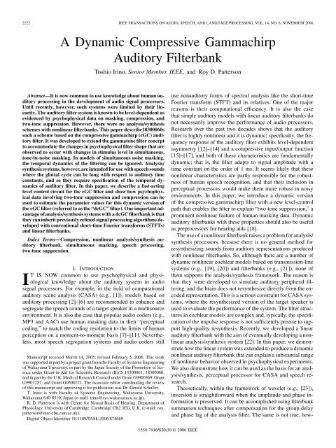
Fig. 2. Set of compressive gammachirp filters (cGC, with peak frequency f )<br />
which are constructed from one passive gammachirp filter (pGC, with peak frequency<br />
f ) and a high-pass asymmetric function (HP-AF) whose center frequency<br />
f shifts up as stimulus level increases, as indicated by the horizontal<br />
arrow [30]. The gain of the cGC filter reduces as level increases, as indicated<br />
by the vertical arrow. The five filter shapes were calculated for probe levels of<br />
30, 40, 50, 60, and 70 dB using the parameter values listed in the second row of<br />
Table I.<br />
Conceptually, this compressive gammachirp is composed<br />
of a level-independent, “passive” gammachirp filter (pGC)<br />
that represents the passive basilar membrane, and<br />
a level-dependent, high-pass asymmetric function (HP-AF)<br />
that simulates the active mechanism in the<br />
cochlea. The filter is referred to as a “compressive” gammachirp<br />
(cGC) because the compression around the peak<br />
frequency is incorporated into the filtering process itself. The<br />
HP-AF makes the passband of the composite gammachirp more<br />
symmetric at lower levels.<br />
Fig. 2 illustrates how a level-dependent set of compressive<br />
gammachirp filters (cGC; upper set of five solid lines; left ordinate)<br />
can be produced by cascading a fixed passive gammachirp<br />
filter (pGC; lower solid line; right ordinate) with a set of highpass<br />
asymmetric functions (HP-AF; set of five dashed lines;<br />
right ordinate). When the leftmost HP-AF is cascaded with the<br />
pGC, it produces the uppermost cGC filter with most gain. The<br />
HP-AF shifts up in frequency as stimulus level increases and, as<br />
a result, at the peak of the cGC, gain decreases as stimulus level<br />
increases [30]. The filter gain is normalized to the peak value of<br />
the filter associated with the highest probe level, which in this<br />
case is 70 dB.<br />
The angular variables are rewritten in terms of the center<br />
frequency and bandwidth of the passive gammachirp filter and<br />
the level-dependent asymmetric function to accommodate the<br />
shifting of the asymmetric function relative to the basilar membrane<br />
function with level. If the filter center frequencies are<br />
and , respectively, then from (4)<br />
(5)<br />
and<br />
The peak frequency<br />
and the center frequency<br />
of pGC is<br />
of HP-AF is defined as<br />
In this form, the chirp parameters, and , can be fixed, and<br />
the level dependency can be associated with the frequency ratio<br />
. The peak frequency of the cGC is derived from numerically.<br />
The frequency ratio is the main level-dependent<br />
variable when fitting the cGC to the simultaneous masking data<br />
[30], [31]. The total level at the output of the passive GC<br />
was used to control the position of the HP-AF. Specifically<br />
The superscripts 0 and 1 designate the intercept and slope of the<br />
line.<br />
In Fig. 2, as the signal level increases, the peak frequency of<br />
the cGC filter first increases slightly and then decreases slightly,<br />
because the pGC filter is not level independent in the current<br />
model. It would be relatively easy to include monotonic leveldependency<br />
in the peak frequency of the cGC filter by introducing<br />
a level-dependency in the asymptotic frequency of<br />
the pGC filter. In this case, the pGC filters would not necessarily<br />
(6)<br />
(7)<br />
(8)
IRINO AND PATTERSON: DYNAMIC COMPRESSIVE GAMMACHIRP AUDITORY FILTERBANK 2225<br />
TABLE I<br />
COEFFICIENT VALUES FOR THE COMPRESSIVE GAMMACHIRP FILTER IN<br />
PATTERSON et al. [31] AND THE CURRENT STUDY. P , P , AND P ARE IN<br />
DECIBELS. IS IN MILLISECONDS AND WAS VARIED BETWEEN 0 AND 5ms<br />
WHEN WE CALCULATED THE EFFECT OF THE HALF-LIFE IN SECTION III-B<br />
The asymmetric compensation filter [22], [33] is defined in the<br />
-plane as<br />
(11)<br />
(12)<br />
(13)<br />
otherwise<br />
(14)<br />
be equally spaced along the ERB rate axis. It is, however, beyond<br />
the scope of this paper because 1) the level-dependent peak<br />
frequency cannot be estimated from the notched noise masking<br />
data used to determine the coefficients of the current cGC filter,<br />
2) a small amount of peak fluctuation does not affect the output<br />
of the filterbank much since adjacent filters tend to shift together<br />
in the same direction, and 3) it is simpler to use a linear pGC<br />
filter for the discussion of analysis/synthesis filterbanks.<br />
A detailed description of the procedure for fitting the gammachirp<br />
to the psychophysical masking data is presented in<br />
[31, Appendix B]. Briefly, the five gammachirp filter parameters<br />
, , , , and were allowed to vary in the fitting<br />
process; was fixed at 4. The filter coefficients were found to<br />
be largely independent of peak frequency provided they were<br />
written in terms of the critical band function (specifically, the<br />
ERB rate function [14], [31]). So, each filter parameter can<br />
be represented by a single coefficient. The parameter has<br />
to change with level and so it requires two coefficients. This<br />
means that a dynamic, compressive gammachirp filterbank that<br />
explains masking and two-tone suppression data for a very wide<br />
range of center frequencies and stimulus levels can be described<br />
with just six coefficients [31], whose values are as listed in the<br />
second row of Table I.<br />
B. Time Domain Implementation<br />
The description above is based on the frequency-domain response<br />
of the gammachirp filter. For realistic applications, it is<br />
essential to define the impulse response. The following is a brief<br />
summary of implementation; the details are presented in [22],<br />
[30], and [33].<br />
The high-pass asymmetric function does not have<br />
an analytic impulse response. So, an asymmetric compensation<br />
filter was developed to enable simulation of the cGC impulse<br />
response, in the form<br />
Here, is a constant, is the gammachirp impulse<br />
response from (1), and is the impulse response of the<br />
asymmetric compensation filter that simulates the<br />
asymmetric function such that<br />
(9)<br />
(10)<br />
otherwise<br />
(15)<br />
(16)<br />
where , , , and are positive coefficients; is the sampling<br />
rate; and is the number of filters in the cascade. When<br />
(which is the case throughout this paper)<br />
and<br />
With these values, the discrepancy between and<br />
is small in the critical region near the asymptotic frequency<br />
[33]. Since the asymmetric compensation filter is always accompanied<br />
by the bandpass filter of the gammatone or gammachirp<br />
filter, the error in the combined filter is reliably reduced to less<br />
than 1 dB within the wide range required by parameters and<br />
. It is also the case that the impulse responses are in excellent<br />
agreement. The coefficients and are functions of the parameters<br />
and . So, it is also possible to derive the values on<br />
a sample-by-sample bases even when and are time-varying<br />
and level-dependent, although it is not the case of the current<br />
simulation.<br />
Since the asymmetric compensation filter is a minimum phase<br />
filter, it is possible to define the inverse filter which is<br />
(17)<br />
since the numerator and denominator in (12) are invertible depending<br />
on the sign of . The inverse filter is a low-pass filter<br />
when the analysis filter is a high-pass filter, so that their product<br />
is unity. The crucial condition is to ensure that it is possible to<br />
invert the filtered signal, even when the parameters , , and<br />
vary with stimulus level [22], [33]; the coefficients used in the<br />
analysis are preserved and precisely applied in the synthesis.<br />
In the current study, it is sufficient to preserve the temporal sequences<br />
of the estimated levels since the gammachirp parameters<br />
are level-independent except for , which is a linear function<br />
of the level as in (8).<br />
Fig. 1 shows the block diagram of the cGC analysis/synthesis<br />
filterbank. The initial block is a bank of linear pGC filters;<br />
the second block is a bank of HP-AF filters which simulate<br />
the high-pass asymmetric function in (9) and (10). We refer to<br />
both the high-pass filter and the high-pass function as “HP-AF”
2226 IEEE TRANSACTIONS ON AUDIO, SPEECH, AND LANGUAGE PROCESSING, VOL. 14, NO. 6, NOVEMBER 2006<br />
(upper blocks) has a pGC with parameters , , , and an<br />
HP-AF with parameters , , . The components<br />
of the level-estimation path are essentially the same as<br />
those of the signal path; the difference is the level-independent<br />
frequency ratio, . The peak frequency of the pGC in<br />
the level-estimation path is required to satisfy the relationship<br />
(18)<br />
Fig. 3. Block diagram of the dcGC filter illustrating how the pGC and HP-AF in<br />
a higher frequency channel (f ) are used to estimate the level for the HP-AF<br />
in the signal path of the dcGC filter with channel frequency f .<br />
for simplicity, since there is a one-to-one correspondence between<br />
them. Together, this cascade of filterbanks represent the<br />
dcGC filterbank; the architecture of the dcGC filter itself is described<br />
in the next section. After arbitrary signal processing of<br />
the dcGC output, it is possible to resynthesize the sound: 1) The<br />
outputs of filterbank are applied to a bank of low-pass asymmetric<br />
compensation filters (LP-AFs) that is the inverse of the<br />
HP-AF filterbank as in (17) and has level-dependent coefficients<br />
based on the estimated level at the analysis filterbank. (2) The<br />
linearized filterbank outputs are applied to a time-reversed pGC<br />
filterbank and then summed up across the channel. When there<br />
is no signal processing between the analysis and resynthesis<br />
stages, the resynthesized sound is almost indistinguishable from<br />
the input sound. The degree of precision is determined by the<br />
passband of the linear pGC filterbank and the density of the filters.<br />
There are many possible variations of the architecture, depending<br />
on the purpose of the signal processing. For example,<br />
in Section III-C, we demonstrate resynthesis from compressed<br />
speech by removing the LP-AF filterbank; under normal circumstances,<br />
the original, noncompressed speech is recovered as<br />
described above.<br />
C. Filter Architecture<br />
Preliminary simulations had shown that the previous cGC filterbank<br />
with six coefficients (second row in Table I) could not<br />
explain two-tone suppression data (e.g., [34], [35]). So, we had<br />
to modify the filterbank architecture. Since the cGC has a precise<br />
frequency response, it is possible to simulate two-tone suppression<br />
in the frequency domain just as we did when fitting the<br />
simultaneous masking data. This greatly reduces the simulation<br />
time required to find a reasonable candidate for the filter architecture<br />
from the enormous number of possible variations. The<br />
result was the filter architecture shown in Fig. 3.<br />
As in the previous compressive gammachirp [31], there are<br />
two paths which have the same basic elements; one path is for<br />
level-estimation and the other is for the main signal flow. The<br />
signal path (bottom blocks) has a pGC filter with parameters ,<br />
, , and a HP-AF with parameters , , .<br />
This combination of pGC and HP-AF results in the compressive<br />
gammachirp (cGC) defined in (5) with peak frequency .<br />
The parameter values are the same as in the previous study and<br />
are listed in the fourth row of Table I. The level-estimation path<br />
where is the rate at frequency [13],<br />
[14], and is a parameter that represents the frequency separation<br />
between the two pGC filters on the ERB rate axis.<br />
The output of the level-estimation path is used to control the<br />
level-dependent parameters of the HP-AF in the signal path. In<br />
order to account for the different rates of growth of suppression<br />
in the upper and lower suppression regions [35], it was necessary<br />
to use not only the level at the output of the pGC as in the<br />
previous cGC [31], but also the level of the output of the HP-AF.<br />
The level was estimated in decibels on a sample-by-sample<br />
basis and used to control the level in the signal path.<br />
If the outputs of the pGC and HP-AF in the level-estimation<br />
path are and , then the estimated linear levels and are<br />
given by<br />
and<br />
(19)<br />
where is the sampling time, and is the half-life of the exponential<br />
decay. It is a form of “fast-acting slow-decaying” level<br />
estimation. The estimated level tracks the positive output of the<br />
filter as it rises in level, but after a peak, the estimate departs<br />
from the signal and decays in accordance with the half-life. The<br />
effect of the half-life on the simulation of compression is illustrated<br />
in Section III-B. The control level is calculated as<br />
a weighted sum of these linear levels in decibels.<br />
and<br />
(20)<br />
where , , and are weighting parameters, and is<br />
a parameter for the reference level in decibels.<br />
In the filterbank, the asymptotic frequencies of the pGC<br />
filters are uniformly spaced along the ERB scale. The peak<br />
frequencies of the pGC filters are also uniformly spaced<br />
and lower than the asymptotic frequencies , since in<br />
(7). The peak frequencies of the dcGC filters are, of course,<br />
level-dependent and closer to the asymptotic frequencies of<br />
the pGC filters. The resultant filterbank is referred to as a dcGC<br />
auditory filter.<br />
We used an equal-loudness contour (ELC) correction to simulate<br />
the outer- and middle-ear transfer functions [13], [14] in the
IRINO AND PATTERSON: DYNAMIC COMPRESSIVE GAMMACHIRP AUDITORY FILTERBANK 2227<br />
following simulations. The ELC filter is implemented with an<br />
FIR filter, and it is possible to define an inverse filter for resynthesis.<br />
D. Computational Cost<br />
The computational cost of a filterbank is one of important<br />
properties, particularly in realtime applications. We estimated<br />
the computational cost in terms of the total number of filters<br />
in the system. The cGC filter consists of a gammatone filter<br />
(GT), a lowpass asymmetric compensation filter (LP-AF), and a<br />
highpass asymmetric compensation filter (HP-AF) as in (5). The<br />
GT filter is implemented with a cascade of four second-order IIR<br />
filters [36]. The LP-AF and HP-AF filters are also implemented<br />
with a cascade of four second-order IIR filters. So, there are a<br />
total of 12 second-order IIR filters for one channel of the signal<br />
path. Since the pGC filter in the level-estimation path of one<br />
cGC filter is identical to the pGC in the signal path of a cGC filter<br />
with a higher peak frequency, it is not necessary to calculate<br />
the output of the pGC filter in the level-estimation path twice.<br />
The HP-AF in the level estimation path is necessary and is also<br />
implemented as a cascade of four second-order IIR filters. So, in<br />
total, one channel in the analysis filterbank requires calculation<br />
of 16 second-order IIR filters.<br />
For the synthesis filterbank, it is necessary to use a cascade<br />
of four second-order IIR filters per channel for the LP-AF filter<br />
(inverse of HP-AF) to linearlize the nonlinear representation.<br />
The temporally-reversed gammachirp filterbank is not essential<br />
when considering the cost because the synthesis is accomplished<br />
with a filtebank summation technique after compensating<br />
for the group delay and phase lag of the analysis filter.<br />
The maximum group delay is defined as the group delay of the<br />
gammachirp auditory filter with the lowest center frequency; it<br />
is just under10 ms when the lowest center frequency is 100 Hz.<br />
The computational cost increases linearly with the number of<br />
channels. It is, however, possible to reduce the cost considerably<br />
by down sampling. It should now be possible to produce a<br />
real time version of the analysis and synthesis components. So,<br />
the total computational cost would largely depend on the cost<br />
of the signal processing implemented between the analysis and<br />
synthesis filterbanks.<br />
In the current study, we used two filterbanks—one for the<br />
two-tone suppression data and one for the compression data.<br />
The suppression filterbank had 100 channels covering the frequency<br />
range from 100 to 4000 Hz (i.e., ERBNrates from 3.4<br />
to 27) The compression filterbank also had 100 channels with a<br />
frequency range from 100 to 15 000 Hz (i.e., rates from<br />
3.4 to 39). The filter densities were 4.2 and 2.8 filters per ERB<br />
rate, respectively, which was sufficient to obtain reasonbly accurate<br />
paramater values. The sampling rate was 48 000 Hz, and<br />
no down sampling was used since the fitting procedure does not<br />
need to run in real time. The maximum center frequency of the<br />
auditory filter needs to be less than one quarter of the sampling<br />
rate in order to define the filter impulse response properly. In<br />
the simulation of compression, however, there was no problem<br />
since the maximum frequency of the signal components was<br />
6000 Hz and the sampling rate was 48 000 Hz.<br />
III. RESULTS<br />
This section illustrates the use of the dcGC filterbank to simulate<br />
two-tone suppression and compression, and the potential<br />
of the filterbank in speech processing. The dcGC filter parameters<br />
, , , , and (Table I) are essentially the same<br />
values as for the previous cGC filter used to fit the simultaneous<br />
masking data [31]. These specific values were determined with<br />
a fitting procedure that was constrained to minimize the number<br />
of free parameters as well as the rms error of the fit. The frequency<br />
ratio parameters, , in the level-estimation path is<br />
1.08 so that the peak gain of the cGC is 0 dB when the peak<br />
gain of the pGC is 0 dB, as it is in this simulation. The other<br />
level-estimation parametes , , , , and were<br />
set to the values listed in the bottom row of Table I which were<br />
derived from preliminary simulations.<br />
A. Two-Tone Suppression<br />
Two-tone suppression [34], [35] is one of the important characteristics<br />
for constructing an auditory filterbank. The amplitude<br />
of the basilar membrane in response to a “probe” tone at a given<br />
frequency is reduced when a second “suppressor” tone is presented<br />
at a nearby frequency at a higher level. The suppressor<br />
dominates the level-estimation path of the dcGC (Fig. 3) where<br />
it increases the compression of the probe tone by shifting the<br />
HP-AF of the signal path.<br />
The method for simulating suppression is simple. A probe<br />
tone about 100 ms in duration and 1000 Hz in frequency is presented<br />
to the filterbank, and the output level of the filter with the<br />
peak at the probe frequency is calculated, in decibels, for various<br />
suppressor tones. Fig. 4 shows the suppression regions (crosses)<br />
and the probe tone (triangle). They show combinations of suppressor-tone<br />
frequency and level where the suppressor-tone reduces<br />
the level of the filter output at the probe frequency by more<br />
than 3 dB. There are regions both above and below the probe frequency.<br />
The solid curve shows the “excitatory”filter, that is, the<br />
inverted frequency response of the dcGC with a peak frequency<br />
of 1000 Hz, when the probe tone level is 40 dB. The dashed lines<br />
centered at about 1100 and 1300 Hz show the “suppressive”filters,<br />
that is, the inverted frequency response curves of the pGC<br />
and cGC in the level estimation path, respectively. When the<br />
estimated level of an input signal increases, the HP-AF in the<br />
signal path moves upward in the frequency and reduces or “suppresses”<br />
the output level of the signal path. The two-tone suppression<br />
is produced by the relationship between these excitatory<br />
and suppressive filters.<br />
The dashed and dotted lines show the suppression regions<br />
observed psychophysically with the pulsation threshold technique<br />
[35]; the simulated suppression regions are quite similar<br />
to the observed regions except for the upper-left corner of the<br />
high-frequency region. The discrepancy arises partially because<br />
the upper skirt of the dcGC filter is shallower than what is usually<br />
observed in physiological measurements. The current parameters<br />
were derived from two large databases of human data<br />
on simultaneous masking without any constraints on the upper<br />
slope. The simulated suppression areas could be manipulated to<br />
produce a better fit by changing the filter parameters if and when<br />
the correspondence between the physiological and psychophysical<br />
data becomes more precise. The current example serves to
2228 IEEE TRANSACTIONS ON AUDIO, SPEECH, AND LANGUAGE PROCESSING, VOL. 14, NO. 6, NOVEMBER 2006<br />
Fig. 5. Relative level of the output of the dcGC for a 1000-Hz probe tone, as<br />
a function of suppressor level, when the suppressor frequency is either 400 Hz<br />
(left panel) or 1400 Hz (right panel). The numbers in the left-hand side show<br />
the probe level in decibels SPL. The output level is normalized to 50-dB SPL<br />
by shifting a constant decibel value. There is suppression whenever the probe<br />
level drops below its starting value where the suppressor is 20-dB SPL.<br />
Fig. 4. Simulation of two-tone suppression data. The probe tone is shown by<br />
the triangle. The suppression regions are shown with crosses. The dashed and<br />
dotted lines show the suppression regions observed psychophysically with the<br />
pulsation threshold technique [34]. The solid curve shows the filter shape of<br />
the cGC for the probe tone on its own. The dashed curves show the inverted<br />
frequency response curves of the pGC and cGC in the level estimation path,<br />
respectively.<br />
demonstrate that the dcGC filter produces suppression naturally<br />
and it is of roughly the correct form.<br />
At this point, it is more important to account for the asymmetry<br />
in the growth of suppression with stimulus level in the<br />
lower and upper suppression regions [35]. Plack et al. [16] reported<br />
that the current dual resonance nonlinear (DRNL) model<br />
[21] could not account for the asymmetry in growth rate even<br />
when the parameters were carefully selected. Fig. 5 shows the<br />
relative output level of the dcGC filter for a 1000-Hz probe<br />
tone, as a function of suppressor level, when the suppressor frequency<br />
is either 400 Hz (left panel) or 1400 Hz (right panel).<br />
It is clear that the absolute growth rate of the suppression for<br />
the lower suppressor frequencies is greater than for the upper<br />
suppressor frequencies. It is also the case that the suppressor<br />
levels are different for the “bend points” (or “break points” in<br />
[35, Fig. 11]), where the output level starts to decrease as the<br />
suppressor level increases. The bend-point levels for a 40-dB<br />
probe tone are about 60 dB for 400 Hz and 40 dB for 1400 Hz.<br />
This difference it appears to be largely due to the difference in<br />
the curvature of the suppression curve; it is more acute in the<br />
lower region and more gradual in the upper region.<br />
The maximum absolute growth rate is about 0.4 dB/dB when<br />
the suppressor frequency is 400 Hz. In contrast, the maximum<br />
slope is about 0.3 dB/dB when the suppressor frequency is 1400<br />
Hz. Note that the output level is compressed by the very nature<br />
of the dcGC architecture, and the degree of compression<br />
increases as the probe level increases. The observed decrement<br />
in the depth for the 60-dB tone does not necessarily mean the<br />
actual suppression slope decreases. To avoid the effect of compression,<br />
the degree of suppression was measured in terms of the<br />
input signal level so that the output level at the probe frequency<br />
was unchanged before and after the suppressor was introduced.<br />
Using this criterion, the growth rates in the model data increase<br />
slightly to about 0.5 and 0.3 dB/dB, respectively, when the probe<br />
is 40-dB sound pressure level (SPL). The suppression levels in<br />
psychophysical data vary considerably with listener and level<br />
[35]; the rates are 0.5–3 dB/dB for a 400-Hz suppressor as in<br />
[35, Fig. 4], and less than 0.2 dB/dB for one subject (no data for<br />
other subjects) for a 1400-Hz suppressor as in [35, Fig. 10]. The<br />
reason for the variability across listeners and levels is unclear.<br />
The growth rates in the lower frequency suppressor are generally<br />
much larger than the rates in the current simulation. We<br />
could change the level-estimation parameter values or modify<br />
the level estimation function in (20) to accommodate the data.<br />
It is, however, not currently clear which set of data is the most<br />
appropriate or reliable, and so we will not pursue the fitting further<br />
in this paper. We did, however, confirm that we were able<br />
to change the depth of suppression for 400- and 1400-Hz suppressors<br />
by changing the weight parameters , , and .<br />
For current purposes, it is sufficient to note that the dcGC filter<br />
produces two-tone suppression, the growth rate is greater on<br />
the low-frequency side of the probe tone, and qualitatively, at<br />
least, the model is consistent with psychophysical data unlike<br />
the DRNL filter model [16], [21].<br />
B. Compression<br />
<strong>Compressive</strong> nonlinearity is also an important factor in<br />
the auditory filterbanks. Oxenham and Plack [15] estimated<br />
the compression characteristics for humans using a forward-masking<br />
paradigm. They also explained the data using<br />
a DRNL filter model [21]. This section shows how the dcGC<br />
filter can also explain the compression data.<br />
1) Method: The experiment in question [15] was performed<br />
as follows: a brief, 6000-Hz, sinusoidal probe was presented at<br />
the end of a masker tone whose carrier frequency was either<br />
3000 or 6000 Hz, depending on the condition. The probe envelope<br />
was a 2-ms Hanning window to restrict spectral splatter; the<br />
duration of the masker was 100 ms. In addition, a low-level noise<br />
was added to the stimulus to preclude listening to low-level,<br />
off-frequency components. Threshold for the probe was measured<br />
using a two-alterative, forced choice (2AFC) procedure in<br />
which the listener was required to select the interval containing
IRINO AND PATTERSON: DYNAMIC COMPRESSIVE GAMMACHIRP AUDITORY FILTERBANK 2229<br />
Fig. 6. Compression data from [15] (thick dashed lines) and simulations of the<br />
data with dcGC filters in which the half-life for level estimation varies from 0<br />
to 5 ms (thin solid lines).<br />
the probe tone. The level of the masker was varied over trials to<br />
determine the intensity required for a criterion level of masking.<br />
The dcGC filter was used to simulate the experiment as follows:<br />
The output of each channel of the dcGC filterbank was rectified<br />
and low-pass filtered to simulate the phase-locked neural<br />
activity pattern (NAP) in each frequency channel, and then the<br />
activation was averaged using a bank of temporal windows to<br />
simulate the internal auditory level of the stimulus. The window<br />
was rectangular in shape, 20-ms in duration, and located to include<br />
the NAPs of the end of the masker and the probe. The<br />
shape of the temporal window does not affect the results because<br />
it is a linear averaging filter and the temporal location of<br />
the probe tone is fixed. The output levels for all channels were<br />
calculated for the masker alone and the masker with probe, and<br />
the array was scanned to find the channel with the maximum difference,<br />
in decibels. The calculation was performed as a function<br />
of masker level in 1-dB steps. Threshold was taken to be the<br />
masker level required to reduce the difference in level between<br />
the two intervals to 2 dB in the channel with the maximum difference.<br />
The half-life of the level estimation was varied to minimize<br />
the masker level at threshold; the remaining parameter<br />
values were exactly the same as in the simulation of the two-tone<br />
suppression data (Table I).<br />
2) Results: Fig. 6 shows the experimental results [15] as<br />
thick dashed lines. The simulation was performed for seven<br />
half-lives ranging from 0 to 5 ms (19), and the results are presented<br />
by thin solid lines. The solid lines above the dotted diagonal<br />
show the simulated threshold when the probe and masker<br />
have different frequencies, namely, 6000 and 3000 Hz. It is clear<br />
that the half-life affects the growth of masked threshold. When<br />
the half-life is 0.5 or 1 ms, the change in the growth rate is very<br />
similar to that in the experimental data (thick dashed line). The<br />
average growth rate is larger in other conditions; it is about 0.5<br />
dB/dB when the half-life is 5 ms and it is more than 0.3 dB/dB<br />
when the half-life is 0.1 ms. When the half-life is 0 ms, the average<br />
slope is close to 0.8 dB/dB which means almost no compression.<br />
So, the level-estimation process must be quick, but not<br />
instantaneous, with a half-life on the order of 0.5–1.0 ms.<br />
The best fit would appear to be for a half-life of 0.5 ms. In<br />
this case, the simulation error is less than 3 dB, since we set the<br />
threshold criterion to 2.0 dB to minimize this error. Threshold<br />
for the condition where the probe and masker have the same<br />
frequency (namely, 6000 Hz) is located a few decibels below<br />
the dotted diagonal line. The threshold functions are almost the<br />
same, despite relatively large half-life differences, and they are<br />
essentially linear input–output functions. This is consistent with<br />
the psychophysical data, at least, for one subject [23]. When the<br />
threshold criterion decreases, the lines for both conditions shift<br />
up in the same way, that is, both when the probe and masker have<br />
the same frequency and when they have different frequencies.<br />
We would still need to explain the subject variability which can<br />
be more than 5 dB when the probe and masker have the same<br />
frequency. We would also need to estimate the half-life for frequencies<br />
other than 6000 Hz, which is not possible currently<br />
because there are no psychophysical data for other frequencies.<br />
In summary, the current model provides a reasonable account<br />
of the compression data; with the exception of the time constant,<br />
the parameters values were identical to those used to explain<br />
two-tone suppression and simultaneous masking.<br />
C. Speech Processing<br />
It appears that the dcGC analysis/synthesis filterbank can<br />
be used to enhance the plosive consonants in speech and the<br />
high-frequency formants of back vowels. The effects are illustrated<br />
in Fig. 7 which shows three “cochlear” spectrograms,<br />
or “cochleograms,” for the Japanese word “aikyaku”; the three<br />
segments of each cochleogram correspond to “ai,” “kya,” and<br />
“ku.” The cochleograms were produced by the pGC filterbank<br />
on its own (a), the linear cGC filterbank without dynamic<br />
level-estimation and when the control level ,wasfixed at 50<br />
dB (b), and the dcGC filterbank with dynamic level-estimation<br />
(c). The output of each filterbank was rectified, averaged for 2<br />
ms with a frame shift of 1 ms, normalized by the rms value of<br />
the whole signal, and plotted on a linear scale. The smearing<br />
of the formants in (a) arises from the fact that the pGC filter<br />
has a much wider passband than either the cGC or dcGC filter.<br />
Compare the representations of the plosives around 350 and<br />
570 ms, and the representation of the high-frequency formants<br />
of the vowel in “ku” in the region beyond 600 ms. The comparisons<br />
show that the dcGC filter compresses the dynamic range<br />
of the speech which emphasizes the plosive consonants and the<br />
higher formants of back vowels, and do so without the need<br />
of a separate compression stage like those typically used with<br />
linear auditory filterbanks or short-time Fourier transforms.<br />
Fig. 8 shows excitation patterns (or frequency distributions)<br />
derived from the same speech segment at points centered on<br />
60 ms (a) and 630 ms (b) in the sustained portions of the /a/<br />
and /u/ vowels, respectively. The solid curve was derived by<br />
averaging the output of the dcGC filterbank [Fig. 7(c)] for 21<br />
ms (1024 sample points). The dashed curve was derived from<br />
the output of the linear cGC filterbank [Fig. 7(b)] and the total<br />
rms level was set to the same level as the output of the dcGC<br />
filterbank. The excitation patterns of the nonlinear dcGC and<br />
linear cGC filterbanks are similar but in both cases the dcGC
2230 IEEE TRANSACTIONS ON AUDIO, SPEECH, AND LANGUAGE PROCESSING, VOL. 14, NO. 6, NOVEMBER 2006<br />
Fig. 7. “Cochlear” spectrograms, or cochleograms, for the Japanese word<br />
“aikyaku,” plotted on a linear scale to reveal level differences. (a) pGC filter.<br />
(b) Linear cGC filter. (c) dcGC filter.<br />
Fig. 9. (a) Original speech wave. (b) Resynthesized versions from the linear<br />
cGC analysis/synthesis filterbank. (c) dcGC analysis filterbank with the linear<br />
pGC synthesis filterbank.<br />
Fig. 8. Excitation patterns calculated from the dcGC filterbank (solid line) and<br />
a linear cGC filterbank (dashed line). The time is (a) 60 ms and (b) 630 ms. A<br />
rectangular window with 1024 points was used for averaging the filter output.<br />
The dashed and dotted curve is a level-dependent excitation pattern derived with<br />
a roex filterbank [13].<br />
filterbank increases the relative size of the upper formants, and<br />
the effect is stronger for the /u/ which has the weaker upper<br />
formants [Fig. 8(b)]. The dashed and dotted curve is a leveldependent<br />
excitation pattern derived with a roex filterbank [13],<br />
which is provided for reference. The pattern was calculated from<br />
the signal level produced by a STFT with a hanning window of<br />
1024 points.<br />
The speech can be resynthesized from the cochleograms<br />
using the time-reversed pGC filterbank in which the peak<br />
frequencies are almost the same as those of the cGC and dcGC<br />
filterbanks. The synthesis LP-AF is not required in this case.<br />
The original speech wave is shown in Fig. 9(a); the resynthesized<br />
speech from the linear cGC and dcGC filterbanks<br />
are shown in Fig. 9(b) and (c), respectively. These sounds<br />
are normalized to the rms value of the whole signal. The<br />
resynthesized cGC wave [Fig. 9(b)] is essentially the same as<br />
the original [Fig. 9(a)]. It is clear that the peak factor of the<br />
resynthesized dcGC wave [Fig. 9(c)] is reduced and the relative<br />
level of the plosives has been increased. The sound quality of<br />
the compressed speech is not quite as good as the original, but<br />
it has the advantage of sounding louder for a given rms value.<br />
Fig. 10 shows the compression characteristics (input–output<br />
functions) for the linear cGC and dcGC filterbanks. The sound<br />
pressure level, in decibels, is derived from the rms value of a entire<br />
word. The average and standard deviation of the SPL were<br />
calculated from fifty word segments of speech in a phonetically-balanced<br />
Japanese database. The dashed line with error<br />
bars on the dotted diagonal is for the analysis/synthesis signal<br />
produced with the linear cGC filterbank. The solid line with<br />
error bars is for speech compressed by the dcGC filterbank; the<br />
output level is set to 100-dB SPL for an input level of 90-dB<br />
SPL. The solid line with circles shows the compression characteristic<br />
for the forward-masking condition where the half-life is<br />
0.5 ms, as shown in Fig. 6. The linear analysis/synthesis signal<br />
has variability because the filterbank restricts the passband between<br />
about 100 and 6000 Hz and, thus, the low- and high-frequency<br />
components drop off. The variability of the compressed<br />
speech is less than about 2 dB.<br />
The slope of the input/output (I/O) function is about 0.6<br />
dB/dB which is greater than that for the masking of short probe<br />
tones, where it is about 0.2 dB/dB at minimum. This moderate<br />
slope is reasonable for speech signals because speech consists<br />
of a range of frequency components which interact with each<br />
other; at one moment a component acts like a suppressor and<br />
at another it acts like a suppressee. This is an important observation<br />
for the design of compressors like those in hearing aids<br />
because the degree of compression is different for the simple<br />
tone sounds used to define the compression, and the speech<br />
sounds that the user wants to hear.
IRINO AND PATTERSON: DYNAMIC COMPRESSIVE GAMMACHIRP AUDITORY FILTERBANK 2231<br />
REFERENCES<br />
Fig. 10. Compression characteristics (input–output functions) of the resynthesized<br />
speech sounds. The solid line with error bars shows the compressed speech<br />
from the dcGC filterbank; the dashed line with error bars shows the analysis/synthesis<br />
signal from the linear cGC filterbank; the solid line with circles shows the<br />
compression characteristic for the forward-masking condition where the half life<br />
is 1 ms, as shown in Fig. 5.<br />
The compression of the dcGC filterbank is reminiscent of the<br />
compression in the much simpler wide dynamic range compression<br />
(WDRC) hearing aids [18]. However, both of these compression<br />
processes have a serious drawback. When there is background<br />
noise or concurrent speech, small noise components are<br />
effectively enhanced, and they interfere with the speech components.<br />
It will be essential to introduce noise reduction [28]<br />
and speech segregation (e.g., [1]) in future speech processors.<br />
The analysis/synthesis, dcGC filterbank provides a framework<br />
for the design and testing of advanced auditory signal processors<br />
of this sort.<br />
IV. CONCLUSION<br />
We have developed a dynamic version of the compressive<br />
gammachirp filter with separate paths for level-estimation and<br />
signal processing. We have also developed a complete, analysis/<br />
synthesis filterbank based on the dynamic, compressive gammachirp<br />
auditory filter. We have demonstrated that the filterbank<br />
can simulate the asymmetric growth of two-tone suppression<br />
and the compression observed in nonsimultaneous masking<br />
experiments. The dcGC filterbank provides a framework for the<br />
development of signal processing algorithms within a nonlinear<br />
analysis/synthesis auditory filterbank. The system enables one<br />
to manipulate peripheral representations of sounds and resynthesize<br />
the corresponding sounds properly. Thus, it provides an<br />
important alternative to the conventional STFTs and linear auditory<br />
filterbanks commonly used in audio signal processing.<br />
The new analysis/synthesis framework can readily inherit refined<br />
signal processing algorithms developed previously in the<br />
linear domain. This framework should be useful for various applications<br />
such as speech enhancement and segregation [1]–[6],<br />
[28], speech coding [7]–[11], and hearing aids [18].<br />
[1] P. Divenyi, Ed., Speech Separation by Humans and Machines. Norwell,<br />
MA: Kluwer, 2004.<br />
[2] G. J. Brown and M. P. Cooke, “Computational auditory scene analysis,”<br />
Comput. Speech Lang., vol. 8, pp. 297–336, 1994.<br />
[3] M. Slaney, D. Naar, and R. F. Lyon, “<strong>Auditory</strong> model inversion for<br />
sound separation,” in Proc. IEEE Int. Conf. Acoust., Speech Signal<br />
Process. (ICASSP), 1994, vol. II, pp. 77–80.<br />
[4] D. P. W. Ellis, “Prediction-driven computational auditory scene<br />
analysis,” Ph.D. dissertation, Dept. Elec. Eng Comp. Sci., Mass. Inst.<br />
Technol., Cambridge, 1996.<br />
[5] D. L. Wang and G. J. Brown, “Separation of speech from interfering<br />
sounds based on oscillatory correlation,” IEEE Trans. Neural Netw.,<br />
vol. 10, no. 3, pp. 684–697, May 1999.<br />
[6] T. Irino, R. D. Patterson, and H. Kawahara, “Speech segregation using<br />
an auditory vocoder with event-synchronous enhancements,” IEEE<br />
Trans. Audio, Speech, Lang. Process., vol. 14, no. 6, pp. 2212–2221,<br />
Nov. 2006.<br />
[7] ISO/IEC JTC1/SC29, Coding of Moving Pictures and Associated<br />
Audio for Digital Storage Media at Up to About 1,5 Mbit/s—Part 3:<br />
Audio , ISO/IEC 11172-3, Int. Std. Org. Geneva, Switzerland, 1993.<br />
[8] ISO/IEC JTC1/SC29, Generic Coding of Moving Pictures and Associated<br />
Audio Information—Part 7: Advanced Audio Coding (AAC) ,<br />
ISO/IEC 13 818-7, Int. Std. Org. Geneva, Switzerland, 2004.<br />
[9] T. Painter and A. Spanias, “Perceptual coding of digital audio,” Proc.<br />
IEEE, vol. 88, no. 4, pp. 451–513, Apr. 2000.<br />
[10] F. Baumgarte, “Improved audio coding using a psychoacoustic model<br />
based on a cochlear filter bank,” IEEE Trans. Speech Audio Process.,<br />
vol. 10, no. 7, pp. 495–503, Oct. 2002.<br />
[11] ——, “Application of a physiological ear model to irrelevance reduction<br />
in audio coding,” in Proc. AES 17th Int. Conf. High Quality Audio<br />
Coding, 1999, pp. 171–181.<br />
[12] R. A. Lutfi and R. D. Patterson, “On the growth of masking asymmetry<br />
with stimulus intensity,” J. Acoust. Soc. Amer., vol. 76, no. 3,<br />
pp. 739–745, 1984.<br />
[13] B. R. Glasberg and B. C. J. Moore, “Derivation of auditory filter shapes<br />
from notched-noise data,” Hear. Res., vol. 47, pp. 103–138, 1990.<br />
[14] B. C. J. Moore, An Introduction of the Psychology of Hearing, 5th ed.<br />
Oxford, U.K.: Academic, 2003.<br />
[15] A. J. Oxenham and C. J. Plack, “A behavioral measure of basilar-membrane<br />
nonlinearity in listeners with normal and impaired listening,” J.<br />
Acoust. Soc. Amer., vol. 101, pp. 3666–3675, 1997.<br />
[16] C. J. Plack, A. J. Oxenham, and V. Drga, “Linear and nonlinear processes<br />
in temporal masking,” Acta Acust., vol. 88, pp. 348–358, 2002.<br />
[17] C. J. Plack, The Sense of Hearing. London, U.K.: Lawrence Erlbaum<br />
Associates, 2005.<br />
[18] H. Dillon, Hearing Aids. New York: Thieme Medical Publishers,<br />
2001.<br />
[19] E. Zwicker and H. Fastl, Psychoacoustics—Facts and Models—.<br />
New York: Springer-Verlag, 1990.<br />
[20] C. Giguère and P. C. Woodland, “A computational model of the auditory<br />
periphery for speech and hearing research. I. Ascending path,” J.<br />
Acoust. Soc. Amer., vol. 95, pp. 331–342, 1994.<br />
[21] R. Meddis, L. P. O’Mard, and E. A. Lopez-Poveda, “A computational<br />
algorithm for computing nonlinear auditory frequency selectivity,” J.<br />
Acoust. Soc. Amer., vol. 109, pp. 2852–2861, 2001.<br />
[22] T. Irino and M. Unoki, “An analysis/synthesis auditory filterbank based<br />
on an IIR implementation of the gammachirp,” J. Acoust. Soc. Japan<br />
(E), vol. 20, no. 6, pp. 397–406, 1999.<br />
[23] J. M. Combes, A. Grossmann, and P. Tchamitchian, Wavelets. Berlin,<br />
Germany: Springer-Verlag, 1989.<br />
[24] L. R. Rabiner and R. W. Schafer, Digital Processing of Speech Signals.<br />
Englewood Cliffs, NJ: Prentice-Hall, 1978.<br />
[25] T. Yang, K. Wang, and S. Shamma, “<strong>Auditory</strong> representations of<br />
acoustic signals,” IEEE Trans. Inf. Theory, vol. 38, no. 2, pp. 824–839,<br />
Mar. 1992.<br />
[26] T. Irino and H. Kawahara, “Signal reconstruction from modified auditory<br />
wavelet transform,” IEEE Trans. Signal Process., vol. 41, no. 12,<br />
pp. 3549–3554, Dec. 1993.<br />
[27] M. Slaney, “Pattern playback from 1950 to 1995,” in Proc. IEEE<br />
Systems, Man, Cybernetics Conf., Vancouver, BC, Canada, 1995, pp.<br />
3519–3524.<br />
[28] J. S. Lim, “Speech enhancement,” in Proc. ICASSP, 1986, pp.<br />
3135–3142.<br />
[29] T. Irino and R. D. Patterson, “A time-domain, level-dependent auditory<br />
filter: the gammachirp,” J. Acoust. Soc. Amer., vol. 101, no. 1, pp.<br />
412–419, 1997.
2232 IEEE TRANSACTIONS ON AUDIO, SPEECH, AND LANGUAGE PROCESSING, VOL. 14, NO. 6, NOVEMBER 2006<br />
[30] ——, “A compressive gammachirp auditory filter for both physiological<br />
and psychophysical data,” J. Acoust. Soc. Amer., vol. 109, no. 5,<br />
pp. 2008–2022, 2001.<br />
[31] R. D. Patterson, M. Unoki, and T. Irino, “Extending the domain of<br />
center frequencies for the compressive gammachirp auditory filter,” J.<br />
Acoust. Soc. Amer., vol. 114, pp. 1529–1542, 2003.<br />
[32] R. D. Patterson, M. Allerhand, and C. Giguere, “Time-domain modeling<br />
of peripheral auditory processing: a modular architecture and<br />
a software platform,” J. Acoust. Soc. Amer., vol. 98, pp. 1890–1894,<br />
1995.<br />
[33] M. Unoki, T. Irino, and R. D. Patterson, “Improvement of an IIR asymmetric<br />
compensation gammachirp filter,” Acoust. Sci. Tech., vol. 22, no.<br />
6, pp. 426–430, 2001.<br />
[34] T. Houtgast, “Psychophysical evidence for lateral inhibition in<br />
hearing,” J. Acoust. Soc. Amer., vol. 51, pp. 1885–1894, 1972.<br />
[35] H. Duifhuis, “Level effects in psychophysical two-tone suppression,”<br />
J. Acoust. Soc. Amer., vol. 67, pp. 914–927, 1980.<br />
[36] M. Slaney, “An Efficient Implementation of the Patterson-Holdsworth<br />
<strong>Auditory</strong> <strong>Filterbank</strong>.” Apple Computer Technical Rep. #35, 1993.<br />
Toshio Irino (SM’04) was born in Yokohama, Japan,<br />
in 1960. He received the B.S., M.S., and Ph.D. degrees<br />
in electrical and electronic engineering from<br />
the Tokyo Institute of Technology, Tokyo, Japan, in<br />
1982, 1984, and 1987, respectively.<br />
From 1987 to 1997, he was a Research Scientist<br />
at NTT Basic Research Laboratories, Tokyo Japan.<br />
From 1993 to 1994, he was a Visiting Researcher at<br />
the Medical Research Council—Applied Psychology<br />
Unit (MRC-APU, currently CBU), Cambridge, U.K.<br />
From 1997 to 2000, he was a Senior Researcher in<br />
ATR Human Information Processing Research Laboratories (ATR HIP). From<br />
2000 to 2002, he was a Senior Research Scientist in NTT Communication Science<br />
Laboratories. Since 2002, he has been a Professor of the Faculty of Systems<br />
Engineering, Wakayama University, Wakayama, Japan. He is also a Visiting<br />
Professor at the Institute of Statistical Mathematics. The focus of his current<br />
research is a computational theory of the auditory system.<br />
Dr. Irino is a member of the Acoustical Society of America (ASA), the Acoustical<br />
Society of Japan (ASJ), and the Institute of Electronics, Information and<br />
Communication Engineers (IEICE), Japan.<br />
Roy D. Patterson was born in Boston, MA, on May<br />
24, 1944. He received the B.A. degree from the University<br />
of Toronto, Toronto, ON, Canada, in 1967 and<br />
the Ph.D. degree in residue pitch perception from the<br />
University of California, San Diego, in 1971.<br />
From 1975 to 1995, he was a Research Scientist for<br />
the U.K. Medical Research Council, at their Applied<br />
Psychology Unit, Cambridge, U.K., focusing on the<br />
measurement of frequency resolution in the human<br />
auditory system, and computational models of the auditory<br />
perception. He also designed and helped implement<br />
auditory warning systems for civil and military aircraft, railway maintenance<br />
equipment, the operating theaters and intensive care wards of hospitals,<br />
and most recently, fire stations of the London Fire Brigade. Since 1996, he has<br />
been the Head of the Centre for the Neural Basis of Hearing, Department of<br />
Physiology, Development, and Neuroscience, University of Cambridge, Cambridge,<br />
U.K. The focus of his current research is an “<strong>Auditory</strong> Image Model”<br />
of auditory perception and how it can be used to: 1) normalize communication<br />
sounds for glottal pulse rate and vocal tract length and 2) produce a size-invariant<br />
representation of the message in communication sounds at the syllable<br />
level. He has published over 100 articles in JASA and other international journals.<br />
Dr. Patterson is a Fellow of the Acoustical Society of America.